
Abstract
Objective: The applications of single-structure fiber-reinforced composite (FRC) in restorative dentistry have not been well reported. This study aimed to clarify the static mechanical properties of anterior crown restorations prepared using two types of single-structure FRC.
Materials and methods: An experimental crown restoration was designed for an upper anterior incisor. The restorations were made from IPS Empress CAD for CEREC (Emp), IPS e.max® CAD (eMx), experimental single-structure all-FRC (a-FRC), Filtek™ Supreme XTE (XTE), and commercially available single-structure short-FRC (everX Posterior™) (n = 8 for each material) (s-FRC). The a-FRC restorations were prepared from an experimental FRC blank using a computer-aided design and manufacturing (CAD/CAM) device. A fracture test was performed to assess the fracture load, toughness, and failure mode. The fracture loads were vertically applied on the restorations. The surface micromorphology of the FRC restorations was observed by scanning electron microscopy (SEM). The data were analyzed by analysis of variance (p = .05) followed by Tukey's test.
Results: s-FRC showed the highest mean fracture load (1145.0 ± 89.6 N) and toughness (26.2 ± 5.8 Ncm) among all the groups tested. With regard to the micromorphology of the prosthetic surface, local crushing of the fiberglass was observed in s-FRC, whereas chopped fiberglass was observed in a-FRC.
Conclusions: The restorations made of short-FRC showed a higher load-bearing capacity than those made of the experimental all-FRC blanks for CAD/CAM. The brittle-like fractures were exhibited in the recent dental esthetic materials, while local crushing fractures were shown for single-structure FRC restorations.
Introduction
Despite their excellent esthetic appearance and superior biocompatibility, dental ceramic restorations are characterized by brittle mechanical properties as well as comparably low fatigue resistance during mastication.[Citation1] On the other hand, the clinical applications of fiber-reinforced composite (FRC) have attracted attention over the last two decades because of its outstanding adhesion and esthetic appearance due to translucency.[Citation2] The acceptable success rates achieved by fixed partial dentures made of FRC support its potential use as a restorative material.[Citation2,Citation3]
As reported in large number of clinical studies,[Citation4–6] catastrophic failures are still the most frequent type of failure for prosthetic restorations made of brittle materials, including resin composites and dental ceramics. Previous studies also indicated the relatively low fracture resistance of conventional FRC restorations due to their bi-layered structure, which consists of a fiberglass substructure and veneering composite.[Citation7] Moreover, anisotropy of the unidirectional FRC, of which the bi-layered FRC substructure is composed, does not provide a gradient-like structure from the substructure of fiberglass to the veneered resin composite. In spite of the potentially adequate mechanical properties of their fiberglass substructure, bi-layered FRC prostheses have been frequently reported to be clinical failures, e.g. the fracturing and delamination of veneered resin composite occurring in high stress-bearing applications.[Citation8,Citation9] It has clearly been shown that single-structure FRC is necessary to provide clinically acceptable mechanical properties instead of the previous multi-structure FRC restorations.
The first possibility for preparation of single-structure FRC restorations came about with the all-FRC restoration fabricated from FRC blocks using computer-aided design and manufacturing (CAD/CAM). As with previous FRC restorations, it is necessary for the fiberglass to include a substructure of matrix resin composite due to the difficulty of forming fiberglass into a desired shape.[Citation10] However, fiberglass can be uniformly oriented in FRC restorations if the restorations are prepared from FRC blocks by CAD/CAM using embedded fiberglass. A successful attempt at preparing all-FRC restorations using a CAD/CAM system was reported by Nagata et al. [Citation7] It was concluded that CAD/CAM is a reasonable option for providing all-FRC prosthetic restorations that would overcome the concentration of negative stress observed with conventional multi-layered FRC restorations. Unidirectional FRC prepared using CAD/CAM has been reported in a previous study,[Citation7] but multi-directional FRC has not been reported yet.
As an alternative possibility, a novel short fiber-reinforced composite (short-FRC) can be assembled for a single-structure FRC restoration. Short-FRC was launched in the dental industry for use as the bulk base material in large cavities of either vital or non-vital posterior teeth in order to increase the load-bearing capacity of the restorations.[Citation11] Short-FRC consists of a combination of a resin matrix, discontinuous E-glass fibers, and inorganic particulate fillers. The short discontinuous fiberglass is said to be oriented during the filling of the cavity with the resin composite. The resin matrix of the short-FRC contains cross-linked bisphenol-A diglycidyl ether dimethacrylate, triethylene glycol dimethacrylate, and linear polymethyl methacrylate, which forms during polymerization of a semi-interpenetrating polymer network (semi-IPN). Semi-IPN has excellent bonding properties and provides a more durable resin composite.[Citation11,Citation12] Previously, the application of short-FRC for single restorations has been discussed,[Citation13,Citation14] and the random orientation of short-FRC provides an isotropic reinforcing effect, which is independent of the direction of the fracture forces, as reported by Vishu.[Citation15] Nevertheless, short-FRC has not been well investigated in terms of its application as a prosthetic material for single-structure restorations.
Therefore, it was hypothesized that single-structure FRC restorations, i.e. either experimental all-FRCs made by CAD/CAM or manually veneered short-FRCs, would have mechanical properties suitable for anterior single restorations. Thus, the purpose of the present study was to ascertain the static mechanical properties of anterior single-structure FRC restorations under experimental masticatory conditions. The comparison was described using recently available major restorative materials, including conventional particulate filler resin composite (PFC), leucite-reinforced ceramic, and lithium di-silicate.
Materials and methods
An experimental abutment for a crown restoration of the maxillary central incisor was cut from presintered zirconium oxide blank (Zirconia Prettau® 95H22, Zirkonzahn GmbH, Gais, Italy) using a CAD/CAM device (5-TEC, Zirkonzahn GmbH). Next, the abutment was sintered in a furnace (Zirkonofen 600/V2, Zirkonzahn GmbH) according to the product instructions. A photoimpression was taken of the sintered zirconium oxide abutment () using another dental CAD/CAM device (CEREC, Sirona Dental Systems Inc., Long Island City, NY). A single-structure crown restoration was designed, and a flat surface was created at the incisor edge in order to adapt the loading cell during the fracture test. A total of 40 crown restorations were prepared as designed using the CAD/CAM device. The crown restorations were allocated to five groups according to the fabrication methods (n = 8).
Figure 1. An experimental abutment die for crown restorations made of zirconium oxide (a). An experimental crown restoration adhered on the abutment die. A dotted line describes the non-anatomic flat surface that is created at the incisor edge of a crown restoration (b). A commercially available dental ceramic block for a CAD/CAM (upper) and an experimental all-FRC block for CAD/CAM (lower) (c). Aluminum foils were placed between the incisor edge of the crown restoration and the load cell during the fracture test (d). Abbreviations: CAD/CAM: computer-aided design and manufacturing; FRC: fiber-reinforced composite.
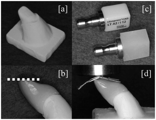
First, for the leucite-reinforced ceramic (Emp group), CAD/CAM blocks made of sintered leucite-reinforced ceramic (IPS Empress CAD for CEREC, Ivoclar Vivadent, Schaan, Liechtenstein) were mechanically fixed with the CAD/CAM device (CEREC) and then crown restorations were simply prepared using a milling manufacturing procedure ().
Table 1. Materials used in the study.
Second, for the lithium di-silicate glass ceramic (eMx group), presintered CAD/CAM blocks (IPS e.max® CAD, Ivoclar Vivadent) were milled by the CAD/CAM device (CEREC). The crown restorations were then crystallized in a curing oven (programat CS®, Ivoclar Vivadent) according to the product instructions ().
Third, for single-structure all-FRC (a-FRC group), experimental discontinuous FRC blocks were prepared before the CAD/CAM procedures. A 16 wt% volume of silanized multidirectional E-glass fibers (13 mm in length; everStick fiber, GC Dental, Tokyo, Japan) was mixed with 26 wt% of photopolymerizable dimethacrylate resin matrix (Stick Resin, GC Dental), and 58 wt% of silanized silica filler particles (SiO2, Aldrich, Steinheim, Germany). The filler particles were added gradually to create a homogeneous structure after mixing the fibers and resins.[Citation16] A high-speed mixing machine (SpeedMixer, DAC, Hauschild, Germany) was used at 3500 rpm for 5 min. For polymerization of the experimental FRC blocks, a semi-interpenetrating polymer matrix was formed from di-methacrylate (). Following photopolymerization and heat polymerization of the FRC resin in a light curing oven (Targis Power, Ivoclar Vivadent, Tamboré, Brazil) at 95 °C for 30 min, the experimental FRC CAD/CAM blocks were created with dimensions of 15 mm ×12 mm ×10 mm (). The block was adhered to a fixing pin with a self-adhesive resin cement (RelyX™, 3M ESPE, St. Paul, MN) as shown in . Next, the experimental all-FRC CAD/CAM blocks were mechanically fixed in the CAD/CAM device (CEREC) for the crown restorations.
Lastly, for preparation of PFC (XTE group) and single-structure short-FRC (s-FRC group), commercially available resin composite products, i.e. a PFC (Filtek™ Supreme XTE, 3M ESPE) and a short-FRC (everX Posterior, GC Dental), were used for the XTE group and s-FRC group, respectively. The compositions of PFC and short-FRC are shown in . A transparent addition-cured silicone impression material (Memosil 2, Heraeus Kulzer GmbH, Hanau, Germany) was used to create an index of a crown restoration made by CAD/CAM to aid in standardizing the manually veneered restorations. The resin composite pastes were packed into the space created between the index and the zirconium oxide abutment, followed by photo-polymerization for 30 s in the laboratory-curing oven (Targis Power). The identities of the manually veneered restorations and CAD/CAM restorations were ascertained by photo-impression (5-TEC).
The restorations were tightly bonded to the zirconium oxide model using a luting cement (Relyx Unicem2, 3M ESPE). The zirconium oxide model with the restoration was then placed at the metal base of the testing device before being statically loaded. In order to load onto the flat incisor surface under the same conditions for all tested restorations, 10 sheets of aluminum foils were placed above the flat surface (). The static compressive fracture test was performed using a universal test machine (LR30K Plus, Lloyd Instruments Ltd., Fareham, UK) with a crosshead speed of 1 mm/min until the crown restorations fractured. The fracture load and the toughness of each crown restoration were recorded. The toughness was automatically calculated by the universal test machine, and the end of the calculations was determined either by fracture or by the load being dropped down 30% from the maximum load. Simultaneously, the failure patterns of the loaded restorations were visually analyzed. In order to observe the effect of milling during CAD/CAM on the prosthetic surfaces of the FRC restorations, a scanning electron microscope (model 5500, JEOL Ltd., Tokyo, Japan) was used. The prosthetic surfaces of the single-structure FRCs were gold-sputtered in an argon atmosphere using a sputter coater (Bal-Tec SCD 050 Sputter Coater; Bal-Tec AG, Balzers, Liechtenstein) before analysis under a magnification of either ×100 or ×500. The statistical analysis was performed by a one-way analysis of variance, followed by Tukey's test. p < .05 was considered to be statistically significant. Analyses were performed using Statistical Package for Social Science version 20 software (IBM Corp., Armonk, NY).
Results
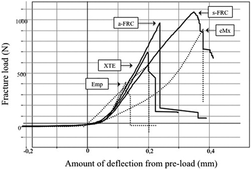
The mean (± standard deviation) fracture load and toughness of the single restorations are given in . Analysis of variance revealed that the s-FRC group had a significantly (p < .05) higher fracture load (1145.0 ± 89.6 N) than the other groups, whereas the Emp group showed the lowest values (448.0 ± 69.1 N) of the groups tested (p < .05). No statistically significant differences (p > .05) were found between restorations in the eMx group (806.7 ± 148.3 N) and those in the a-FRC group (913.6 ± 86.3 N). The typical stress-strain curves of the restorations are shown in . With regard to the toughness of the single restorations, the s-FRC group showed the highest values (26.2 ± 5.8 Ncm), while the lowest toughness values were observed in the Emp group (2.6 ± 0.7 Ncm).
Figure 2. The mean values for the fracture load (N) (bars) and toughness (Ncm) (line) of the crown restorations. The vertical lines represent the standard deviations. The stars above the columns indicate that there is no significant difference between the eMx group and the a-FRC group for fracture load. Abbreviations: FRC: fiber-reinforced composite.
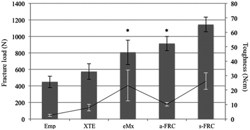
Figure 3. The graph shows typical load-strain curves of all tested crown restorations.
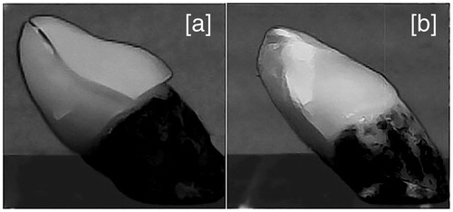
Visual inspection revealed two types of fracture patterns according to the materials used (). Catastrophic failure occurred in the Emp, XTE and eMx groups, whereas partial fracture occurred in the a-FRC and s-FRC groups.
Figure 4. The typical fracture appearance of restorations made from brittle materials (Emp, XTE and eMx groups) (a) and restorations made from single-structure FRCs (a-FRC and s-FRC groups) (b). For the restorations made from the brittle materials, catastrophic failures were observed in which an initial crack initiated the fracture with a single fracture line (a). For restorations made from single-structure FRCs, local crushing failures were observed (b). The restorations made from FRCs maintained their original shapes until fracture, although multiple fracture cracks occurred in the incisor edge of the restorations. Abbreviation: FRC: fiber-reinforced composite.
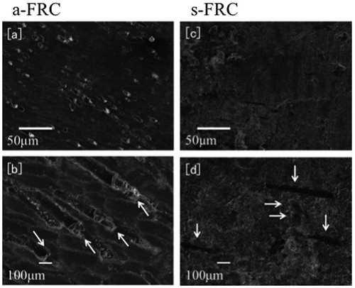
Scanning electron micrographs of the prosthetic surface in the a-FRC group revealed chopped fiberglass with matrix resin, while fiberglass was present parallel to the prosthetic surface in the s-FRC group ().
Figure 5. Scanning electron micro-morphologies show the prosthetic surfaces of crown restorations made from single-structure FRCs. The surfaces of a-FRC with magnifications of ×100 and of ×500 are shown in (a) and (b), whereas those of s-FRC with magnifications of ×100 and ×500 are presented in (c) and (d), respectively. Sections of chopped fiberglass were observed on the surface of a-FRC as indicated by arrows in (b), whereas parallel oriented fibers were present on the surface of s-FRC as indicated by arrows in (d). For the surface of s-FRC, the crushed edges of the fiberglass and the lateral side of the oriented fiberglass are indicated by horizontal arrows and vertical arrows, respectively, in (d). Abbreviation: FRC: fiber-reinforced composite.
Discussion
In the present study, the experimental FRC CAD/CAM block consisted of relatively long fiberglass with an original length of 13 mm, while the short-FRC consisted of randomly oriented short fiberglass with an average length of 0.9 mm. The short-FRC has previously been reported to exhibit high fracture toughness and load-bearing capacity.[Citation11,Citation12] Thus, we hypothesized that FRC could sustain the loads required for crown restorations made either of manually veneered short-FRC or of experimental all-FRC CAD/CAM blocks.
The results of the fracture test support our hypothesis because FRC restorations (a-FRC and s-FRC groups) showed a substantial improvement in load-bearing capacity and toughness when compared with PFC (XTE group; ). The reinforcing effect of the fiberglass is based on the stress transfer from the polymer matrix to the fiberglass, as well as the behavior of the crack obstruction within individual pieces of fiberglass. Moreover, single-structure FRC prevents occurrence of cracks between the veneered resin site and the FRC substructure, which destroy traditional multi-structure FRC restorations. As a result, single-structure FRC restorations (a-FRC and s-FRC groups) show higher fracture behavior than PFC and the dental ceramics that have recently become available (XTE, Emp and eMx groups).
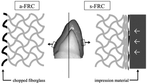
Interestingly, the fracture load of the all-FRC restoration (a-FRC group) was significantly lower than that of the veneered short-FRC (s-FRC group), although the basic composition was similar and the FRC CAD/CAM blocks contained longer fibers (). This could be explained by the difference in fiber orientations on the prosthetic surfaces between the veneered short-FRC and the all-FRC prepared by the milling procedure. According to the scanning electron micrographs of the prosthetic surface, all-FRC (a-FRC group) had chopped fiberglass on the prosthetic surface, whereas more parallel oriented fibers were present on the surface of the veneered short-FRC (s-FRC group) (). The milling procedure during the CAD/CAM resulted in chopped fiberglass on the prosthetic surface of the all-FRC (, left), while CAD/CAM application supported the use of single-structure FRC restorations. On the other hand, the short-FRC paste was packed and crashed by the template matrix against the model during preparation of veneered short-FRC restorations in this study (, right). Therefore, the distribution of fiberglass on the prosthetic surface of the veneered short-FRC restorations was reoriented from the original random three-dimensional orientation to a random two-dimensional orientation in the s-FRC group, whereas most of the fiberglass on the surface was chopped on the prosthetic surface of all-FRC. This finding is in accordance with that of Garoushi et al.,[Citation17] who demonstrated a high fracture resistance in continuous short-FRC containing fibers with a length of a few millimeters.
Figure 6. A schematic drawing of the distinct distributions of fiberglass (black lines) on the prosthetic surfaces of single-structure FRC restorations. The fiberglass in a-FRC was chopped during the milling of CAD/CAM (left), while the fiberglass in s-FRC was crushed by the impression material during the preparation (right). Abbreviations: CAD/CAM: computer-aided design and manufacturing; FRC: fiber-reinforced composite.
Another possible reason why the veneered short-FRC restorations exhibited better mechanical behavior than the all-FRC restorations is that the toughness of the all-FRC restorations was lower than that of the veneered short-FRC restorations. This finding could be explained by the difference in brittleness between the veneered short-FRC and the all-FRC under the polymerization conditions used for the FRC in the present study. While the CAD/CAM blocks were well polymerized with photo-curing and heat-curing, the veneered short-FRC was polymerized by photo-curing without heat-curing. Consequently, the all-FRC was more brittle than the veneered short-FRC in the present study. In terms of the effect of the type of curing on FRCs, Kim and Okuno [Citation18] reported that resin composite tended to possess more brittle behavior when it was heat-polymerized in addition to photo-polymerization, because photo-curing and heat-curing thoroughly polymerizes the monomer of the resin composite, whereas photo-curing only results in incomplete polymerization. In the present study, the all-FRCs were more brittle than the short-FRCs, because the CAD/CAM FRCs were photo-polymerized and heat-polymerized while the short-FRCs were only photo-polymerized.
In the present study, the fracture loads were evenly applied to the incisor edge area, which is considered to be the most crucial area of the maxillary central incisor from a mechanical point of view.[Citation19] According to the visual inspection following the fracture test, the cracks in the crown restorations made of PFC and dental ceramics (Emp, XTE, and eMx groups) originated at a similar point, near the flat surface of the incisor edge area. This result may indicate that the fracture load was evenly applied on the flat surface of all of the experimental crown restorations. Additionally, the aluminum sheets that were placed between the restorations and the load tip offered stable loading condition.
Generally, the fracture resistance of a dental restoration would be determined by an individual investigator, which means that a standard for the measurement of prosthetic failure measurement does not exist in the dental materials field. For example, Dyer et al. [Citation20] have reported either the initial cracking or the final failure measure, whereas Nagata et al.[Citation7] insisted that the load that caused the initial crack of the FRC would be the same as the clinical failure load for a prosthetic FRC. In the present study, instead of considering both the initial fracture and the maximum fracture load, the maximum force at the final fracture was defined as the fracture load of the restorations in order to clarify the comparison. However, it should be stressed that initial cracks appeared in single-structure FRC restorations (a-FRC and s-FRC groups) before failure occurred with the maximum fracture load.
According to visual analysis of the fracture pattern of the restorations, two patterns of prosthetic failure were found among the materials used in this study. In the Emp, XTE, and eMx groups, brittle fracture was observed, and single restorations were fractured in several pieces (). It can be clearly seen that the brittleness of the particulate filler composite and glass ceramic materials caused the brittle fracture. On the other hand, only partial failure, which retains the original shape of the crown restoration despite the occurrence of multiple cracks, was observed in the a-FRC and s-FRC groups (). The initial crack occurred on the incisor edge of the restorations, and the crack initiated failure by crushing the resin composite in the a-FRC and s-FRC groups (). The fracture load values presented for all tested restorations were greater than the reported maximum mastication force (143.9 N) in the anterior region.[Citation21] The fracture test also gives valuable information concerning the load-bearing capacity because of the linear relationship between fatigue and static loading.[Citation22]
Further studies are needed to demonstrate the effect of aging cyclic mechanical stress, wear, and abrasiveness of the surface characteristics and function of bulk FRC restorations.
Conclusions
Within the limitations of this experimental study, the following conclusions can be made:
Single-structure FRC restorations showed higher fracture resistance than the restorations made from PFC, leucite-reinforced ceramic, and lithium di-silicate.
The restoration made from light-cured manually veneered FRC showed higher load-bearing capacity than that from those made from light-cured and heat-cured FRC blocks using CAD/CAM.
Chopped fiberglass was revealed on the prosthetic surface of CAD/CAM-fabricated FRC restorations, whereas parallel-oriented fiberglass was observed on that of manually veneered short-FRC restorations.
The fracture types were brittle-like fractures for resin composite and dental ceramics, while local crushing fracture occurred with the FRC restorations.
Disclosure statement
The authors report no conflicts of interest. The authors alone are responsible for the content and writing of this article.
References
- Morena R, Beaudreau GM, Lockwood PE, et al. Fatigue of dental ceramics in a simulated oral environment. J Dent Res. 1986;65:993–997.
- Vallittu PK. Survival rates of resin-bonded, glass fiber reinforced composite fixed partial dentures with a mean follow-up of 42-months: a pilot study. J Prosthet Dent. 2004;91:241–247.
- vanHeumen CC, Tanner J, van Dijken JW, et al. Five-year survival of 3-unit fiber-reinforced composite fixed partial dentures in the posterior area. Dent Mater. 2010;26:954–960.
- Sjögren G, Lantto R, Granberg A, et al. Clinical examination of leucite-reinforced glass-ceramic crowns (Empress) in general practice: a retrospective study. Int J Prosthodont. 1999;12:122–128.
- Lekesiz H. Reliability estimation for single-unit ceramic crown restorations. J Dent Res. 2014;93:923–928.
- Pallesen U, Qvist V. Composite resin fillings and inlays. An 11-year evaluation. Clin Oral Investig. 2003;7:71–79.
- Nagata K, Wakabayashi N, Takahashi H, et al. Fracture resistance of CAD/CAM-fabricated fiber-reinforced composite denture retainers. Int J Prosthodont. 2013;26:381–383.
- Gohring TN, Roos M. Inlay-fixed partial dentures adhesively and reinforced by glass fiber: clinical and scanning electron microscopy analysis after five years. Eur J Oral Sci. 2005;113:60–69.
- Waki T, Nakamura T, Kinuta S, et al. Fracture resistance of inlay-retained fixed partial dentures reinforced with fiber-reinforced composite. Dent Mater J. 2006;25:1–6.
- Maruo Y, Nishigawa G, Irie M, et al. Flexural properties of polyethylene, glass and carbon fiber-reinforced resin composites for prosthetic frameworks. Acta Odontol Scand. 2015;73:581–587.
- Garoushi S, Säilynoja E, Vallittu PK, et al. Physical properties and depth of cure of a new short fiber reinforced composite. Dent Mater. 2013;29:835–841.
- Garoushi S, Vallittu PK, Lassila LVJ. Short glass fiber reinforced restorative composite resin with semi-interpenetrating polymer network matrix. Dent Mater. 2007;23:1356–1362.
- Garoushi S, Vallittu PK, Lassila LV. Fracture resistance of short, randomly oriented, glass fiber-reinforced composite premolar crowns. Acta Biomater. 2007;3:779–784.
- Garoushi S, Vallittu PK, Lassila LVJ. Use of short fiber-reinforced composite with semi-interpenetrating polymer network matrix in fixed partial dentures. J Dent. 2007;35:403–408.
- Vishu S. Handbook of plastic testing technology. 2nd ed. New York: Wiley; 1998.
- Söderholm KJ, Yang MC, Garcea I. Filler particle leachability of experimental dental composites. Eur J Oral Sci. 2000;108:555–560. ]
- Garoushi S, Lassila LVJ, Tezvergil A, et al. Load bearing capacity of fibre-reinforced and particulate filler composite resin combination. J Dent. 2006;34:179–184.
- Kim KH, Okuno O. Microfracture behaviour of composite resins containing irregular-shaped fillers. J Oral Rehabil. 2002;29:1153–1159.
- Esquivel-Upshaw JF, Clark AE, Shuster JJ, et al. Randomized clinical trial of implant-supported ceramic-ceramic and metal-ceramic fixed dental prostheses: preliminary results. J Prosthodont. 2014;23:73–82.
- Dyer SR, Sorensen JA, Lassila LV, et al. Damage mechanics and load failure of fiber-reinforced composite fixed partial dentures. Dent Mater. 2005;21:1104–1110.
- Pereira-Cenci T, Pereira LJ, Cenci MS, et al. Maximal bite force and its association with temporomandibular disorders. Braz Dent J. 2007;18:65–68.
- Garoushi S, Lassila LV, Tezvergil A, et al. Static and fatigue compression test for particulate filler composite resin with fiber-reinforced composite substructure. Dent Mater. 2007;23:17–23.