
Abstract
Objectives: Bonding of zirconia crowns and bridges to abutments is important, not only bonding of the thin resin layer to the abutment, but also bonding to the zirconia ceramic is crucial. Both mechanical and chemical adhesion are desired. Mechanical retention of dental porcelain achieved by etching with moderately concentrated hydrofluoric acid is not possible with zirconia ceramics.
The purpose of this study was to show that etching is possible with relative low melting fluoride compounds such as ammonium hydrogen difluoride and potassium hydrogen difluoride.
Materials and methods: Before melting, the fluorides can be introduced as powders or as aqueous slurries to the contact surfaces of the zirconia. After melting, the yttria-stabilized zirconia surface revealed a surface similar to an HF-etched dental feldspathic porcelain surface. Shear bond testing (n = 10) was performed with zirconia attached to zirconia with the Duo-Link composite luting cement (Bisco) after treatment of the etched zirconia surfaces with Bis-Silane (Bisco) and the Porcelain Bonding Resin (Bisco).
Results: Values for adhesive strength (mean ± standard deviation) after melt etching of the surfaces with initially dry powders were for K[FHF], (31.2 ± 7.5) MPa and for NH4[FHF] (31.0 ± 11.8) MPa. When initially aqueous slurries were applied, the values were for K[FHF] (42.7 ± 12.7) MPa and for NH4[FHF] (40.3 ± 10.0) MPa.
Conclusion: Good adhesion to zirconia can be achieved by a procedure including etching with selected melted fluoride compounds.
Introduction
Due to their high strength and relative high toughness properties zirconia ceramics have been introduced in prosthetic dentistry for the production of, for example, crowns and bridges fixed to implant abutments and prepared natural teeth. Sintered yttria-stabilized tetragonal zirconia polycrystals (Y-TZP) are described as ‘polycrystalline, high-strength oxide ceramics’ without a ‘glass phase’ [Citation1]. Compared to conventional ceramic systems such as feldspatic porcelain or glass ceramics, Y-TZP ceramics have superior mechanical properties opening broad applications in dentistry and therefore Y-TZP are increasingly used. Ceramics based on silicates like dental porcelain and glass ceramics can be etched by hydrofluoric acid (HF in water). To obtain a durable adhesion between resin and such ceramic materials the etched surface must be silanized with an organosilane. The surface structure of Y-TZP ceramics without silicon dioxide in the structure is chemically highly inert and requires alternative techniques of surface treatments to obtain good adhesion. Similar as for silica-based ceramics, it is anticipated that Y-TZP ceramics need surface modification to obtain micromechanical retention and/or chemical bonds between the ceramic surface and the resin cement.
In several review articles, the adhesion of resin-based luting cements to zirconia has been discussed [Citation2].
Some reported methods to enhance zirconia adhesion to resin cement are as follows: (1) surface abrasion with airborne alumina particles or roughening the zirconia surface with diamond bur to create adhesion through micromechanical retention [Citation3,Citation4], (2) use of tribochemical silica coating enables chemical bonds via a silane-coupling agent and the resin cement [Citation5], (3) silica coating carried out as treatment of zirconia ceramic surfaces with plasma spraying with hexamethyldisiloxane and (4) fuzing of porcelain beads to the zirconia [Citation6], (5) etching with hydrofluoric acid by using long-time immersion (1–24 h) in 9.5% HF at 25 °C or for 1–30 min in 9.5% HF at 80 °C. Also immersion in 48% HF at 25 °C for 30 and 60 min has given etching [Citation7].
A process, the so-called ‘selective infiltration etching’ (SIE) introduced to give intergranular porosities at the surface that allows resin cements to flow between the grains, resulting in interlocking [Citation8–11]. To reduce the surface and subsurface damage by airborne particle abrasion, from now called sandblasting [Citation12,Citation13], a modified SIE procedure was introduced [Citation14,Citation15] applying relative small alumina particles (30 and 50 μm) or round 30 μm alumina particles at low pressure for sandblasting of sintered Y-TZP discs.
It has been proposed that the use of phosphate ester primers such as the monomer 10-methacryloyloxydecyldihydrogenphosphate (MDP) and phosphate-modified resin cements may form relatively stable adhesion [Citation16].
Chemical bonding of resins to zirconia has been achieved by fluorination treatment in a plasma reactor with SF6 gas. After contact with atmospheric humidity, the fluorinated zirconia surface becomes hydrolyzed with the formation of reactive surface hydroxyl groups, which can react with phosphate ester containing monomer of an adhesive [Citation17]. It has also been postulated that zirconia oxyfluoride at the surface may react with organosilane to give chemical attachment to resin systems [Citation18].
The purpose of the present study was to develop and evaluate etching procedures of zirconia with two different relatively low-melting fluoride substances applied as powders and aqueous slurries or pastes. The latter is to make it possible to apply the etchant on curved surfaces. The intension of etching was to create an irregular zirconia surface that facilitates for interlocking of resin and resin cement without subsurface damage. Based on the dissolution of ZrO2 in molten KOH with the formation of zirconates and the affinity of fluoride to Zr4+, the melting of the relatively low-melting potassium hydrogen difluoride (KHF2) and ammonium hydrogen difluoride (NH4HF2) were chosen as etching agents [Citation19]. Another intention was also to investigate the influence of different surface treatment methods of the melt-etching procedure with these two compounds compared with sandblasting on simple shear bond strength. Scanning electron microscopy (SEM) and X-ray diffraction analysis were used to characterize structure, phases and phase transformations at the surface of the differently treated zirconia samples. Fourier transform infrared (FTIR) spectroscopy was used to characterize possible reaction products from the etching process.
Materials and methods
Specimen preparation
Hot isostatic pressed (HIP) Y-TZP discs of 13 mm diameter and 1.25 mm thickness were received from Denzir Production AB (CAD Esthetic AB, Skellefteå, Sweden). They were milled from blocks, stated to be sintered at 1500 °C, 2000 bar (200 MPa), 4 d. Y-TZP rods of 5 mm diameter and 3.5 mm thickness were milled from Lava Multi XL blocks (3 M, St. Paul, MN). The rods were sintered at 1500 °C for 2 h in a high-temperature-sintering furnace (Zirkonofen 700 vacuum, Zirkonzahn, Gais, Italy). Each zirconia specimen was ground at a 20-μm diamond disc and polished with 15, 6 and 1 μm DP-spray P (Struers, Copenhagen, Denmark) respectively. Distilled water was used as a coolant during polishing the specimens.
The specimens were steam cleaned with Steam Cleaner X3 (Armann Girrbach, Koblach, Austria), ultrasonically rinsed in distilled water and in ethanol for 15 min each by Finn Sonic m03/m ultrasonic bath (Lahti, Finland) and finally air-dried before surface treatment. The polished, cleaned zirconia discs and rods were randomly divided into 10 groups (10 samples in each group) and subjected to different surface treatments. Two groups were sandblasted (SB), four were etched with potassium hydrogen difluoride, KHF2 (EK) (Fluka Analytical, Sigma-Aldrich, St. Louis, MO) and four with ammonium hydrogen difluoride, NH4HF2 (EA) (Fluka, Sigma-Aldrich, Buchs, Switzerland), respectively. Both etchants were applied as powder (.P) and water-based slurry (.S). One of each treatment groups were silanized (…S), the other were used unsilanized (…U). 10 specimens were fabricated for each group (n = 10). The groups are listed in .
Table 1. Groups listed with abbreviation and surface treatment procedure.
Sandblasting
Both disc and rod specimens were sandblasted with 110 μm alumina particles at one surface with a pressure of 2 bar in 5 s for the rod surfaces and 15 s for the discs. Sandblasted specimens were steam cleaned and rinsed in ultrasonic bath as well (15 min). One group was silanized (SBS) and one group was tested unsilanized (SBU). The silanized sandblasted group is considered as a control group.
Etching
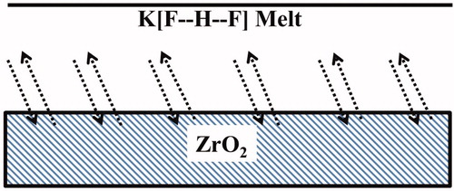
Melting of the fluoride compound KHF2 on ground and polished Y-TZP for 10 min gave a rough etched surface. The KHF2 etchant with a melting point of 239 °C [Citation20] is a particular compound with symmetrical hydrogen bonds in the linear and symmetrical [F••H••F]− ion [Citation21]. An effective etchant is also a melt of the unstable, relatively low melting NH4HF2 with a melting point of 125 °C [Citation20], also with symmetrical hydrogen bonds. These are melt/solid-state reactions with diffusion of fluoride species to the zirconia surface and diffusion of reaction products from the zirconia surface into the melt with partly precipitation at the surface. A schematic view of etching process is shown in .
Figure 1. Schematic view of etching process. Diffusion of active etching agents in the melt and to the solid zirconia surface with simultaneous diffusion of etching products, fluorozirconates, from the zirconia surface and into the melt.
Crystals of KHF2 were ground to fine powder in an agate mortar and the powder was spread on one flat surface of the zirconia discs and rods. The same procedure was also carried out using powder of NH4HF2. The specimens with KHF2 powder were placed on a metal plate and heated in a preheated furnace (Accu-therm II 2000, Jelenko, Armonk, NY) at a temperature of 280 °C, and the specimens with NH4HF2 at 170 °C, both for 10 min.
A small quantity of the powder was mixed with distilled water to viscous slurries (4.0 mg/ml for KHF2 and 4.2 mg/ml for NH4HF2) and spread on one flat surface of zirconia discs and rods. These specimens were heated in the same way and at the same temperature as for the specimens covered with the powder. During the time in the furnace and after water evaporation, the fluoride compounds appeared melted. After 10 min, the plate with the specimens was removed from the oven and bench-cooled.
Etched specimens were steam cleaned, ultrasonically rinsed in water (15 min) and dried in air before silanization.
X-ray diffraction
Six zirconia disc specimens were polished and sintered at 1500 °C for 2 h in a high-temperature-sintering furnace to ensure that the structure was according to the as-sintered state. One specimen was sandblasted with 110-μm alumina particles at 2 bars. Four specimens were etched with KHF2 and NH4HF2 with powder and slurry, respectively. Specimens of different groups after surface treatment and untreated polished specimens were subjected to X-ray diffraction (XRD) to determine the phases present and whether there was a phase transformation due to sandblasting or difluoride etching. The phase distribution and crystallinity of the specimens were characterized using a Bruker D8 Discover diffractometer in Bragg-Brentano geometry with CuKα1 radiation selected by a Ge (111) monochromator with LynxEye detector (Bruker AXS GmbH, Karlsruhe, Germany)) at the Norwegian National Center for XRD and scattering (RECX). Data were collected with a step size of 0.02° and a count time of 0.7 s/step over a 2θ range of 20–120°. The analysis of XRD patterns was performed by the use of Rietveld method [Citation22,Citation23]. Phases were identified using the PDF-2 database in Bruker EVA software and Rietveld analysis was carried out using TOPAS-5 [Citation24]. Crystallite sizes were determined by the Double Voigt approach [Citation25], based on the sample column height from peak integral breadth (Lvol-IB method in TOPAS). A March-Dollase preferred orientation correction in the (1 − 1 −1) direction was applied to the monoclinic phase. Atomic positions were not refined for any of the phases. The background was fitted with a 6-term Chebyshev polynomial function.
FT-IR measurements
In order to understand the chemical composition of the etched surface product, FT-IR (Fourier transform infrared spectrometry) measurements were carried out. The etched surface products derived from the KHF2 etching were isolated from a resulting aqueous dispersion. The melted and precipitated fluoride products were thoroughly washed off the etched surfaces with water and ultrasonically rinsed in distilled water (1–2 min), followed by centrifugation in Heraeus Multifuge X3 FR (Thermo Scientific, Langenbold, Germany) and separated for FT-IR analysis.
The remaining powder was dried and ground with an agate mortar and pestle. Few drops of mineral oil (Nujol, Sigma Aldrich, St. Louis, MO) was added to the powder and mixed well. The liquid suspension was introduced into an IR liquid cell (0.025 mm thick CsI windows, Perkin Elmer, Norfolk, CT) with a syringe. IR spectra were recorded in nitrogen atmosphere in the region 4000–200 cm−1 at a resolution of 2 cm−1 by carrying out 25 scans on an FT-IR spectrometer (Varian 670-IR, Agilent Technologies, Santa Clara, CA). In addition, FT-IR spectra of Nujol and the reference potassium hexafluorozirconate, K2[ZrF6] (Sigma-Aldrich, St. Louis, MO) were examined at room temperature. From the FT-IR spectra of the etched surface product and K2[ZrF6], the Nujol spectrum was subtracted.
Also the remnants from the etching with NH4HF2 were washed and attempted separated. However, all the remnants were dissolved in the water and were not analyzed.
Silanization and cementation
Silanization was carried on the surfaces of the zirconia discs and rods with freshly mixed solutions of the monosilane (3-methacryloyloxypropyltrimethoxysilane) in ethanol and acetic acid also in ethanol to have an effective silane being capable of wetting the etched surfaces, Bis-Silane (Bisco, Schaumburg, IL).
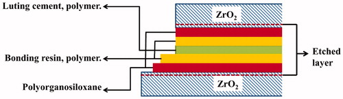
First, a layer of Bis-Silane was applied and the surfaces were dried using compressed air. Next step was coating with a layer of HEMA-free resin (Porcelain Bonding Resin, Bisco, IL). Thereafter, they were joined together with Duo-Link composite luting cement. Zirconia disc and rod was pressed together manually, followed by pressing together by applying a force of 50 N and the resin systems were polymerized using the light source Bluephase (Ivoclar-Vivadent, Amhurst, NY) from four directions for 20 s each. The specimens were stored at 37 °C for 24 h. The material combination of the etched zirconia discs and rods with all bonding layers is schematically shown in .
Figure 2. Schematic illustration of combination of materials (zirconia bonded to zirconia ceramic).
Bond strength measurements
The bond strength between zirconia discs and rods was determined by a shear bond test in accordance with Test 7.7 Bond strength in ISO 10477:2004 [Citation26] using a universal mechanical test machine (Lloyds LRX 9439, Lloyds Instruments Ltd, Fareham, UK) at a crosshead speed of 1 mm/min. Bond strength was calculated by Nexigen MT v4.5 software system (Ametek, Largo, FL).
Statistics
Means and standard deviations of bond strength were calculated for each group and tested statistically using F-test (p < 0.05).
Scanning electron microscopy
The fracture surfaces were examined in two randomly selected specimens from each group after shear bond testing. The specimens were sputter-coated with a layer of gold–palladium and analyzed under a SEM (PHILIPS XL-30 ESEM, Eindhoven, Netherlands) for surface topography analysis.
Results
Shear bond testing
The mean shear bond strength values of all groups are presented in with standard deviations. Sandblasted, unsilanized specimens displayed lowest bond strength, indicating low chemical attachment between Y-TZP surfaces and resin cement. Both the silanized, sandblasted group and all difluoride-etched groups had significantly higher bond strength than the unsilanized, sandblasted group (F-test, p < 0.05).
Table 2. Mean shear bond strength values of all groups tested along with the standard deviation.
Scanning electron microscopy
Scanning electron microscopy (SEM) images of the sandblasted and difluoride etched zirconia disc specimens are presented in . Sandblasted specimen () having different surface morphology than those of etched specimens ()). With 110 μm sandblasting, large grooves and voids were observed on the surface of zirconia ceramic. Etched specimens show a rough surface with exposed homogeneous grains of an average size of 0.3 μm. Etching with the NH4HF2 compound gave a similar surface as those etched with KHF2.
Figure 3. SEM images of the zirconia disc specimens (reference) after different surface treatments (a) Sandblasted; (b) K[FHF] powder, etched; (c) K[FHF] slurry, etched; (d) NH4[FHF] powder etched; (e) NH4[FHF] slurry etched.
![Figure 3. SEM images of the zirconia disc specimens (reference) after different surface treatments (a) Sandblasted; (b) K[FHF] powder, etched; (c) K[FHF] slurry, etched; (d) NH4[FHF] powder etched; (e) NH4[FHF] slurry etched.](/cms/asset/f132f84c-ccc2-47c7-83fd-31dc6542e9bb/iabo_a_1309658_f0003_b.jpg)
Scanning electron microscopy of fracture surface
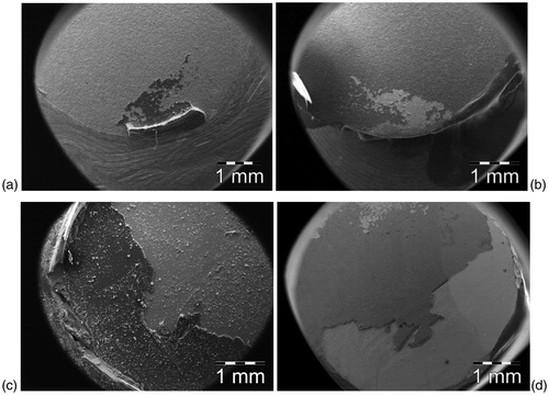
SEM images of the different groups of specimens after shear bond testing are shown in and show the etched surface of zirconia with grains 0.3–0.5 μm in size, which resulted in an inter-granular ‘porosity’ at the surface allowing the silane primer to penetrate and interlock or hook between the grains. Representative images of the fracture surfaces of zirconia disc and rod specimens after shear bond testing are shown in . Specimens with strong bond strength showed a combination of adhesive with bonding agent partly remaining on the zirconia surface.
Figure 4. SEM images of the zirconia disc specimens after shear bond measurements (a) EKPS (b) EKPU and (c) EKSU.
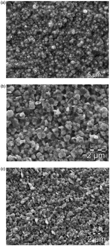
Figure 5. SEM images of the fracture surfaces of zirconia disc and rod specimens after shear bond testing measurements. Light areas are thin layers and darker areas are thicker layers of bonding resin cement. (a) SBS zirconia disc, contact area at the upper part; (b) SBS zirconia rod, contact area at the upper part; (c) EASS zirconia disc, contact area; (d) EASS zirconia rod, contact area.
X-ray diffraction
The Rietveld refinement plots for Y-TZP specimens after different surface treatments are presented in . From , it was evident that no peaks corresponding to monoclinic ZrO2 phase were observed in the polished specimen. It should be noted that the cubic and tetragonal structures of zirconia are very similar (a = 0.5124 nm for cubic, and a = 0.5094 nm and c = 0.5177 nm for tetragonal structures), so many of their diffraction peaks overlap in the 2θ < 70° range. At higher 2θ Bragg angles, however, the cubic phase exhibits single peaks at all reflection positions, whereas the tetragonal peaks split into two [Citation27]. XRD patterns of all specimens show two well-separated reflection lines at 2θ = 73 and 74°.
Figure 6. Rietveld fit to XRD data for Y-TZP specimens after different surface treatments. (a) Polished; (b) Sandblasted; (c) K[FHF] slurry etched; (d) NH4[FHF] slurry etched. Upper plots showing observed and calculated intensities, lower plot shows the difference for the samples. *Monoclinic peak.
![Figure 6. Rietveld fit to XRD data for Y-TZP specimens after different surface treatments. (a) Polished; (b) Sandblasted; (c) K[FHF] slurry etched; (d) NH4[FHF] slurry etched. Upper plots showing observed and calculated intensities, lower plot shows the difference for the samples. *Monoclinic peak.](/cms/asset/6bf4befc-474e-463c-bdcf-d67dfca2deb0/iabo_a_1309658_f0006_c.jpg)
XRD patterns of the etched specimens showed a very sharp low-intensity peak at 2θ = 28°, which corresponds to the monoclinic ZrO2 phase. On the other hand, XRD pattern of the sandblasted specimen showed a broad monoclinic peak at 2θ = 28°. Weak peaks were observed at 2θ = 31 and 34° which probably are due to monoclinic ZrO2 phase.
The quantitative analysis and crystallite size results for the studied specimens are given in , along with the Rwp factors for the fits. Cubic (ICSD 89429) tetragonal (ICSD 23928) and monoclinic (ICSD 26488) ZrO2 phases were used for phase quantification and crystallite size analysis. As mentioned earlier, no monoclinic phase was detected after polishing the specimens. Zirconia surfaces etched with difluorides induced limited, ∼1–2 wt% tetragonal-to-monoclinic phase transformation. The highest fraction of monoclinic phase, ∼15 wt%, was found after sandblasting the zirconia surfaces. Of note are the increase of ∼15 wt% of the cubic phase from 14 wt% to 29 wt% after sandblasting and the reduction of the tetragonal phase to ∼56 wt%.
Table 3. Results of quantitative and crystallite size analysis by the Rietveld method.
FT-IR measurements
From FT-IR measurements, the etched surface product was assumed to be K2[ZrF6] and it was indicated by FT-IR spectra with absorptions at 506, 502, 491, 484, 472 and 468 cm−1 in the region 460–510 cm−1 as shown in . FT-IR spectra of etched surface product in the region 500–205 cm−1 was presented in , which is close to identical to that of commercially available K2[ZrF6] ().
Figure 7. FT-IR spectra of (a) etched surface product and (b) K2[ZrF6] in the region 510–460 cm−1. The figures on the absorption peaks represent wavenumbers and peak areas.
![Figure 7. FT-IR spectra of (a) etched surface product and (b) K2[ZrF6] in the region 510–460 cm−1. The figures on the absorption peaks represent wavenumbers and peak areas.](/cms/asset/f3b9b09d-a659-4551-860e-d8b7077b0c42/iabo_a_1309658_f0007_b.jpg)
Figure 8. FT-IR spectra for (a) etched surface product and (b) K2[ZrF6] in the region 500–200 cm−1.
![Figure 8. FT-IR spectra for (a) etched surface product and (b) K2[ZrF6] in the region 500–200 cm−1.](/cms/asset/9e0f1bfe-cca8-492c-bcb0-c629131248db/iabo_a_1309658_f0008_b.jpg)
Discussion
Good wetting is crucial for obtaining adhesion of restorations with resins. Further a good and durable bonding, both micromechanical retention and chemical adhesion is required [Citation28].
The results of the shear bond tests of zirconia rods bonded to zirconia discs showed good adhesion for all combinations of hydrogen difluoride-etched surfaces with and without silane treatment (). The state of the adhesion between a zirconia rod and a zirconia disc corresponds to a cementation of a crown or frame attached to an abutment (implant or dentin abutment). The adherends are not subject to contraction or strain. Such phenomena only take place in the adhesive layer.
The shear bond data show an improvement in the shear bond strength values by difluoride etching. Highest shear bond strength values (42.7 ± 12.7 and 45.6 ± 11.3 MPa) among the investigated groups were obtained by KHF2 and NH4HF2 etching. This indicates difluoride etching created surface roughness that increased the bond strength.
Low bond strength was obtained with sandblasted zirconia without silane application (5.4 ± 1.7 MPa). Mean shear bond strength values for silanized, sandblasted specimens (26.2 ± 7.4 MPa) were significantly higher. This indicates that silanization involves an important contribution in adhesion between sandblasted zirconia surfaces and resin cement in facilitating wetting of the zirconia surfaces. The freshly mixed solution of the 3-methacryloyloxypropyltrimethoxysilane and acetic acid in ethanol will reduce formation of organosiloxane oligomers at application and have a lesser tendency for wetting the zirconia surface and probably result in a reduced formation of a stable polysiloxane film. With organosiloxane oligomers, the tendency for chemical reaction with the formation of initial intermolecular bonding such as hydrogen bonds with zirconia is also reduced [Citation29].
By sandblasting of zirconia, high surface energy and wettability are normally achieved [Citation30]. It must therefore be assumed that the zirconia surfaces were inactivated by the steamed water treatment and the ultrasonic water bath leaving hydrated surfaces and adsorbed water.
Sandblasted zirconia samples that were silanized exhibited good bonding. However, uncertainty has been expressed that the roughening process applied might introduce flaws, cracks and grain pullouts as well as induce phase transformation of the zirconia, which with time will reduce the strength of the ceramic [Citation1,Citation15,Citation31]. In particular, the formation of cracks and grooves () in the surface together with volume expansion due to transformation from cubic to tetragonal to monoclinic structure may induce stress concentrations [Citation2]. Thus, airborne alumina particles and the accompanying surface defects may degrade the long-term performance in clinical use [Citation32].
reveals the changes between the cubic, tetragonal and monoclinic forms at the surface of Y-TZP before and after sandblasting. After sandblasting, the quantity of cubic form is twice that in the as-sintered material and the tetragonal form is also partly transformed to a volume fraction of 15% monoclinic form.
The formation of cubic zirconia is assumed to originate from the high-energy impact of alumina particles on the zirconia surface leading to very high local temperatures (tetragonal → cubic; phase transition temperature: 2370 °C [pure ZrO2]). The amount of energy released is dependent on mass and velocity of the particles and it has been calculated to give temperatures of several thousand K at the points of impact [Citation33]. In addition, the high-energy alumina particle blasting causes fracture of the grains and zirconia crystals with formation of smaller crystallites at the surface ().
The shear bond strength between zirconia surfaces and the attached resin systems was slightly enhanced for the sample groups that were exposed to the melting difluorides KHF2 and NH4HF2 compared to the silanized, sandblasted group. The slurries of the hydrogen difluorides have been used to achieve good contact with zirconia when applied for crowns and abutments having curved surfaces. Melt etching of zirconia with the fluorides created a rough surface of exposed zirconia grains with deep groves. Moreover, specimens etched with difluorides appear to have similar morphology to that of specimens etched with hydrofluoric acid [Citation7] as shown in the SEM-images in ) and ).
This facilitates the micromechanical retention of resin and luting cement. The silane solution and the uncured liquid resin can penetrate into the irregularities in the zirconia surface. A secondary effect of the etching together with the steam and aqueous ultrasonic treatment is to cleanse the ceramic surface by removing unwanted oxides, debris and precipitates. It is anticipated that during treatment with the melted hydrogen difluorides the surface of zirconia is fluoridated, which after steam and ultrasonic water treatment, becomes hydrolyzed leaving active hydroxyl sites. Hydroxylation of zirconia is indicated, similar to that described by Lohbauer et al [Citation34] from the treatment of zirconia ceramics with a mixture of sulfuric acid and hydrogen peroxide (piranha solution) These hydroxyl groups are reactive with hydroxyl groups of silanoles resulting from hydrolyzed 3-methacryloyloxypropyltrimethoxysilane. This reaction gives hydrogen bonds which, over time, may develop into covalent oxygen bonding between silicon of the organopolysiloxane and the zirconium atoms in the zirconia surface, giving even more stable bondings than hydrogen bonds alone.
The difluorides are hydrogen compounds with symmetric hydrogen bonds with linear anions, K[F••H••F] and NH4[F••H••F]. Based on these circumstances, KHF2 is probably quite stable up to and above the melting point, whereas NH4HF2 decomposes during melting. During the laboratory work and in particular during heating in the oven, good ventilation is required due to released fumes and the toxicity of fluorine compounds and the aggressive nature of hydrofluoric acid [Citation35].
The efficiency of the etching is based on dissolution of ZrO2 in the molten K[F••H••F] and the affinity of F− for Zr4+ and the evaporation of water:
The substance denoted as K2[ZrF6] may also have the Zr coordination number 8 and, as a result, have a more complex structural arrangement than other group IV hexafluorometallates [Citation36–38]. The Zr atom in the lattice is surrounded by eight F atoms, four of which are bridging [Citation39]. The Zr coordination polyhedra share edges and thus form infinite chains [Citation39]. According to calculations performed various numbers of vibrational frequencies for the monomeric, dimeric and polyhedral complexes with coordination numbers 6–8 of potassium fluoro-zirconate compounds have been reported [Citation40]. However, the observed number of bands in the range 600–200 cm−1 in previous published experimental spectra is much smaller, probably due to overlap and coincidence [Citation38,Citation41]. Our experimental FT-IR spectra exhibit a larger number of well-defined IR bands within the wave number range 530–205 cm−1. It is seen that the profile of the bands corresponding to asymmetric stretching vibrations of the terminal Zr–F bonds in the experimental IR spectrum of K2ZrF6 is complicated. Due to the complexity of the K2ZrF6 spectra, no interpretation has been attempted. Recently, Voit et al. [Citation40] assigned the vibrational modes for different Zr based compounds theoretically. In general, theoretically calculated absolute values are not directly comparable with the experimental data. However, one can use this qualitative picture to assign different vibrational modes present in the IR spectra. The Zr–F stretching modes (symmetric and asymmetric) are present above wavenumber 310 cm−1 and F–Zr–F bending modes are present between the wavenumbers 310 and 200 cm−1. In order to understand the origin of the individual peaks, more detailed structural and spectroscopic studies are needed. However, it can be concluded that the substance denoted as K2[ZrF6] was a mixture of potassium fluoro-zirconates, including both monomeric and polymeric anionic complexes.
Conclusions
Melting of the fluoride compounds KHF2 or NH4HF2 on ground and polished Y-TZP gave a rough etched surface suitable for good and durable adhesion to a zirconia implant or dentin abutment.
Acknowledgements
The authors thank Dr. David Wragg at Norwegian National Center for X-ray diffraction and scattering for his XRD analyzing and help in the descriptions of the analyzing method and interpretation of the results. We are also grateful for the zirconia discs, which were supplied from Denzir AB, Skellefteå, Sweden.
Disclosure statement
The authors report no conflicts of interest. The authors alone are responsible for the content and writing of this article.
Additional information
Funding
References
- Papia E, Larsson C, du Toit M, et al. Bonding between oxide ceramics and adhesive cement systems: a systematic review. J Biomed Mater Res Part B Appl Biomater. 2014;102:395–413.
- Chen L, Suh BI. Bonding of resin materials to all-ceramics: a review. Curr Res Dent. 2012;3:7–17.
- Wegner SM, Gerdes W, Kern M. Effect of different artificial aging conditions on ceramic-composite bond strength. Int J Prosthodont. 2002;15:267–272.
- Yang B, Barloi A, Kern M. Influence of air-abrasion on zirconia ceramic bonding using an adhesive composite resin. Dent Mater. 2010;26:44–50.
- Denry IL. Recent advances in ceramics for dentistry. Crit Rev Oral Biol Med. 1996;7:134–143.
- Derand T, Molin M, Kvam K. Bond strength of composite luting cement to zirconia ceramic surfaces. Dent Mater. 2005;21:1158–1162.
- Sriamporn T, Thamrongananskul N, Busabok C, et al. Dental zirconia can be etched by hydrofluoric acid. Dent Mater J. 2014;33:79–85.
- Aboushelib MN, Kleverlaan CJ, Feilzer AJ. Selective infiltration-etching technique for a strong and durable bond of resin cements to zirconia-based materials. J Prosthet Dent. 2007;98:379–388.
- Aboushelib MN, Matinlinna JP, Salameh Z, et al. Innovations in bonding to zirconia-based materials: Part I. Dent Mater. 2008;24:1268–1272.
- Aboushelib MN, Mirmohamadi H, Matinlinna JP, et al. Innovations in bonding to zirconia-based materials. Part II: focusing on chemical interactions. Dent Mater. 2009;25:989–993.
- Aboushelib MN, Feilzer AJ, Kleverlaan CJ. Bonding to zirconia using a new surface treatment. J Prosthodont. 2010;19:340–346.
- Grigore A, Spallek S, Petschelt A, et al. Microstructure of veneered zirconia after surface treatments: a TEM study. Dent Mater. 2013;29:1098–1107.
- Wang H, Aboushelib MN, Feilzer AJ. Strength influencing variables on CAD/CAM zirconia frameworks. Dent Mater. 2008;24:633–638.
- Aboushelib MN, Wang H. Influence of crystal structure on debonding failure of zirconia veneered restorations. Dent Mater. 2013;29:e97–e102.
- Aboushelib MN. Low energy surface activation of zirconia based restorations. Eur J Prosthodont Restor Dent. 2016;24:3–9.
- Kern M, Wegner SM. Bonding to zirconia ceramic: adhesion methods and their durability. Dent Mater. 1998;14:64–71.
- Piascik JR, Swift EJ, Braswell K, et al. Surface fluorination of zirconia: adhesive bond strength comparison to commercial primers. Dent Mater. 2012;28:604–608.
- Piascik JR, Wolter SD, Stoner BR. Development of a novel surface modification for improved bonding to zirconia. Dent Mater. 2011;27:e99–105.
- Cotton FA, Wilkinson G, Murillo CA, Bochmann M, The elements of the second and third transition series. Advanced inorganic chemistry. New York: John Wiley and Sons; 1999. p. 878–885.
- CRC Handbook of chemistry and physics, 88th ed. Boca Raton, FL: CRC press: 2007.
- Ibers JA. Refinement of Peterson and Levy neutron diffraction data on KHF2. J Chem Phys. 1964;40:402–404.
- Rietveld HM. A profile refinement method for nuclear and magnetic structures. J Appl Crystallogr. 1969;2:65–71.
- Young RA, The Rietveld method. Oxford: Oxford University Press & International Union of Crystallography; 1993.
- Coelho AA, TOPAS User Manual: Bruker AXS GmbH; Karlsruhe, Germany; 2003.
- Balzar D, Voigt function model in diffraction-line broadening analysis. In: Microstructure analysis from diffraction. Oxford: Oxford University Press; 1999.
- Dentistry-Polymer-Based Crown and Bridge Materials, ISO 10477:2004; International Organization for Standardization (ISO) 2004.
- Srinivasan R, De Angelis RJ, Ice G, et al. Identification of tetragonal and cubic structures of zirconia using synchrotron x-radiation source. J Mater Res. 1991;6:1287–1292.
- Ruyter IE. The chemistry of adhesive agents. Oper Dent. 1992;32–43.
- Mack H, Silane oligomers: a class of their own. In: Mittal K, editor. Silanes and other coupling agents. 3. 1 ed. Utrecht: Boston; 2004. p. 11–20.
- Su N, Yue L, Liao Y, et al. The effect of various sandblasting conditions on surface changes of dental zirconia and shear bond strength between zirconia core and indirect composite resin. J Adv Prosthodont. 2015;7:214–223.
- Oliveira-Ogliari A, Vasconcelos CS, Bruschi RC, et al. Thermal silicatization: a new approach for bonding to zirconia ceramics. Int J Adhes Adhes. 2014;48:164–167.
- Kosmač T, Oblak Č, Marion L. The effects of dental grinding and sandblasting on ageing and fatigue behavior of dental zirconia (Y-TZP) ceramics. J Eur Ceram Soc. 2008;28:1085–1090.
- Tiller HJ, Magnus B, Gobel R, et al. Der sandstrstrahlprozess und seine einwirkung auf den oberflächenzustand von dentallegierungen (I) [sand-blasting process and its use in surface conditioning of dental alloys (I)]. Quintessenz. 1985;36:1927–1934.
- Lohbauer U, Zipperle M, Rischka K, et al. Hydroxylation of dental zirconia surfaces: characterization and bonding potential. J Biomed Mater Res Part B Appl Biomater. 2008;87:461–467.
- Kirkpatrick JJ, Enion DS, Burd DA. Hydrofluoric acid burns: a review. Burns. 1995;21:483–493.
- Forrest IW, Lane AP. Single-crystal polarized infrared and Raman-spectra and normal-coordinate analysis of some group 4 complex hexafluorometalates. Inorg Chem. 1976;15:265–269.
- Toth LM, Bates JB. Vibrational spectra of crystalline Li2ZrF6 and Cs2ZrF6. Spestrochim Acta. 1974;30A:1095–1104.
- Lane AP, Sharp DWA. Infrared and raman spectra of some group IV complex hexafluorometallates. J Chem Soc A. 1969;2942–2945.
- Hoppe R, Mehlhorn B. Crystal structure of K2ZrF6. Z Anorg Allg Chem. 1976;425:200–208.
- Voit EI, Didenko NA, Galkin KN. Vibrational spectra of zirconium fluoride complexes with different structures of anionic sublattice. Opt Spectrosc. 2015;118:114–124.
- Agulyanskii AI, Zalkind OA, Masloboev VA. Influence of temperature on IR spectra of fluoride complexes of group IV and V elements. Zhurnal Prikladnoi Spektroskopii 1981;39:960–964.