
Abstract
In the present study, amount of titanium (Ti) released into the surrounding bone during placement of implants with different surface structure was investigated. Quantification of Ti released during insertion from three different implants was performed in this ex vivo study. Jaw bone from pigs was used as model for installation of the implants and Inductively Coupled Plasma Atomic Emission Spectroscopy (ICP-AES) was used for analysis of the released Ti. Implant surface were examined with scanning electron microscopy (SEM), before and after the placement into the bone. Ti was abraded to the surrounding bone upon insertion of a dental implant and the surface roughness of the implant increased the amount of Ti found. Diameter and total area of the implant were of less importance for the Ti released to the bone. No visible damages to the implant surfaces could be identified in SEM after placement.
1. Introduction
Titanium (Ti) has been used as a biomaterial for medical and dental implants for decays and are considered as a metal with a good biocompatibility. To be considered as a good biomaterial, a material needs to exhibit excellent biocompatibility and corrosion resistance without cytotoxicity together with good material properties, as high material strength with a good fatigue and wear resistance [Citation1–3].
Dental implants made of Ti are a well-established standard treatment for edentulism today, after the discovery of osseointegration in the 1960 s [Citation4]. As a material for dental implants, Ti is favorable because of its good material characteristics such as mechanical strength, corrosion resistance, chemical stability and biocompatibility. The good biocompatibility of titanium as a material for implants is connected to the properties of the 3–5 nm thick oxide layer formed on the metal surface [Citation5]. Ti is highly resistant to corrosion and is considered to be relatively inert due to the thin TiO2 layer formed on the surface [Citation6]. Corrosion experiments in vivo show that Ti, stainless steel and cobalt-base alloys have a similar polarization resistance, which suggests that high corrosion resistance is not the most essential property for a material to be biocompatible [Citation7]. Ti exists in five naturally occurring isotopes 46–50Ti, but only 47Ti (7.3%) and 49Ti (5.5%) can be used for quantification with Inductively coupled plasma mass spectroscopy (ICP-MS) without interference problems with calcium-, chromium- and vanadium-isotopes [Citation8].
The first generation of implants had a machined surface [Citation9] and was originally described by Brånemark et al. and manufactured by Nobel Biocare (Nobel Biocare Services AG, Zürich, Switzerland) [Citation5,Citation10]. Although the clinical outcome in long-term follow-up studies of implants with a machined surface is good [Citation11,Citation12], but almost every dental implant on the market today has surface modification to give better primary stability and the possibility to achieve an earlier loading time [Citation13–20]. Machined implants show a lower insertion torque and lower friction coefficient as compared with surface-treated implants during placement, and the insertion torque depends on implant geometry, thread form and surface morphology [Citation21]. There are many parameters for measurement of surface roughness, both two or three dimensional. The most commonly used parameters for dental implants are average roughness (Ra) and arithmetical mean height (Sa-value) and the latter is the preferred parameter according Wennerberg et al. [Citation22]. Increasing surface roughness is reported to have a positive correlation with implant integration into bone and the best bone response occurs with a Sa of about 1.5 µm [Citation23–25]. Developed interfacial area ratio (Sdr) is a hybrid surface roughness parameter that expresses the additional surface area in percentage, by summing the area contributed by the texture in comparison to a perfect flat and smooth surface (Sdr = 0%) [Citation26]. In other words, Sdr can be expressed as information about the surface enlargement.
As we earlier showed in an in vitro study, Ti ions form particles that can act as a secondary stimulus to activate and release interleukin (IL)-1β beta from human macrophages [Citation27]. This can act in synergy with an infection-induced inflammation and cause imbalance in the host response. Ti ions might also be responsible for monocyte infiltration in the gingiva by elevating the sensitivity of gingival epithelial cells to microorganisms. Surface roughness might affect osteoclast differentiation by activation of the receptor activator of nuclear factor κB (RANK)- TNF receptor associated factor 6 (TRAF-6) signaling network [Citation28,Citation29]. These findings were repeated by Wachi et al., who also found that Ti ions induced monocyte infiltration and osteoclast differentiation [Citation30].
Schliephake et al. showed with scanning electron microscopy (SEM) that Ti particles were abraded from Ti fixtures and screw taps and the particles were found in the adjacent bone around the insertion in mini-pigs [Citation31]. They also showed that five months after insertion the Ti particles were not found in the bone at the implant site, but were found in high levels in the lungs as compared with other inner organs. Meyer et al. used SEM to investigate bone from peri-implant sites after insertion of implants with varying surface roughness; they found the highest levels of Ti at sites with Ti plasma sprayed implants [Citation32]. They did not find any morphological alterations on a nanoscale level in cells adjacent to the implant sites. It has been shown in the literature that fluoride and low pH can impair the corrosion resistance of Ti, which leads to a high release of Ti ions from the material [Citation33,Citation34]. When commercial-pure (c. p.) Ti was exposed to both stress and chemical corrosion (tribocorrosion), the highest values of tribocorrosion products were found at pH 6 [Citation35]. The author raised concerns because saliva has a pH 6.3 and the tribocorrosion products easily could be sheared off from the surface.
He et al. investigated the content of 47Ti in human jaw bone with dental implants and found the highest intensity of 47Ti adjacent to the implant and the intensity decreased with increased distance from the implant [Citation36]. We have previously found enhanced levels of Ti in tissues adjacent Ti dental implants [Citation27]. In addition, higher levels of Ti were found in the dental plaque of peri-implantitis patients than in implant patients without peri-implantitis [Citation37]. If this is an effect only from corrosion of the Ti material or if there is also wear of Ti during insertion and the effect of surface treatment, has not been thoroughly investigated.
The null hypothesis is that no there are no differences in the amount of Ti released from dental implants with different surface characteristics and diameters.
To test this hypothesis, the aim of this study was to quantify the amount of Ti released during insertion in a model with jaw bone from pigs. Additional aims were to determine if more Ti is abraded from an implant with a rough surface vs. a smooth, machined implant and if the diameter of the installed implant has any influence. Also, to examine if damages to the surface could be detected after insertion into the bone.
2. Materials and methods
2.1 Experimental model
The experiments were carried out on pig mandibles bought from a butchery (Nyhléns Hugosons, Luleå, Sweden). The jaws had their coronoid and condylar process removed at the slaughterhouse before arrival at the department. No ethical clearance was needed because the mandibles are considered as offal from the slaughterhouse.
2.2 Implants and instruments
Fifteen Nobel Brånemark® (Brmk) System Mark(Mk)III machined regular platform (RP) 3.75 × 10 mm implants, fifteen Nobel Brmk System MkIII TiUnite (TiU) RP 3.75 × 10 mm implants, and fifteen Nobel Brmk System MkIV TiU RP 4.0 × 10 mm were donated from Nobel Biocare (Nobel Biocare Services AG, Zürich, Switzerland) for this study. Nobel Brmk System MkIII machined is a cylindrical, self-tapping, turned implant in c. p. grade IV Ti. Nobel Brmk System MkIII TiU is first turned and then the turned surface is anodized [Citation38], to achieve a surface enlargement which exhibits a moderate roughness (). The MkIV TiU implant is surface treated the same way as MkIII TiU, but has a one-degree tapered profile when compared with the cylindrical shape of MkIII. The diameter of the RP implant is 4.0 mm and it is marketed as an implant for soft bone (). Values of the surface roughness (Sa) and surface enlargement (Sdr) are also available in . Total area of the implants was obtained from the implant manufacturer.
Figure 1. Implant- and surface characteristics. Images illustrating implant characteristics and SEM micrographs of the morphology of the implant surface. †Sa value 0.9 μm and Sdr value 34% [Citation71]. ††Sa value 1.1 μm and Sdr value 37% [Citation71]. SEM micrographs (original magnification, †10 kX and ††5 kX).
![Figure 1. Implant- and surface characteristics. Images illustrating implant characteristics and SEM micrographs of the morphology of the implant surface. †Sa value 0.9 μm and Sdr value 34% [Citation71]. ††Sa value 1.1 μm and Sdr value 37% [Citation71]. SEM micrographs (original magnification, †10 kX and ††5 kX).](/cms/asset/fa00f78f-bd7f-4abe-9296-d261113ea5b4/iabo_a_1399270_f0001_c.jpg)
Drills were bought from Nobel Biocare and the drill protocol for RP implants was used according to instructions from the manufacture (start burr, twist drill 1.5–3.2 mm and then counterbore RP).
A surgical handpiece from NSK (Nakanishi Inc., Tochigi, Japan) with a micro bone saw blade was used to cut bone samples from the pig jaw bones.
2.3 Implant surgery and bone samples
Ramus mandible was used as the experimental area of the pig mandibles, due to the good bone quality and a bone area without disturbance of any teeth. A mucoperiosteal flap was carried out on both buccal and lingual sides to expose the bone.
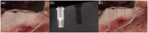
At the first, most anterior test site, the implant site was prepared according to the drill protocol provided by the manufacture, starting with a round burr, then with a twist drill from 1.5 up to 3.2 mm and completing with a counterbore for RP. After the first implant site was prepared another site was prepared 10 mm posterior to the first site. After the two implant sites were prepared the implant to be tested was inserted with an implant motor DEC601 (Nobel Biocare, Gothenburg, Sweden), in the first prepared implant site (). Cooling was provided with physiological saline solution during the drilling procedure and the insertion of the implant. An X-ray was taken to illustrate the bone structure, the implant and the prepared implant site (). After insertion of the implant, the bone was cut vertically with a micro bone saw into three samples during cooling with physiological saline and the installed implant was removed from the bone (). After removal of the implant, the bone samples were cut loose from the mandible with a horizontal cut through the bone into three samples. There were five groups of bone samples: bone control (untreated bone, n = 10), drill control (bone prepared with implant drills, but no implant installed, n = 10) and the implant groups (MkIII machined, n = 14, MkIII TiUnite n = 15, and MkIV TiUnite n = 12). Each jaw was used on both sides with one bone-control sample, one drill-control sample and one implant sample on each side.
Figure 2. Illustrations and radiographs from the insertion procedure in the pig jaw model system. (a) Exposed bone after a mucoperiosteal flap was performed. Two implant sites are prepared and an implant is inserted in the first site. (b) X-ray showing an implant and one prepared implant site (drill control) in the bone. (c) Vertical cuts of the bone with a micro bone saw to separate the implant, the drill control without implant and the bone control without implant or preparation for implantation.
The bone samples were collected into 50 ml plastic tubes, one sample in each tube, and was frozen at −20 °C until further analysis.
2.4 Inductively Coupled Plasma Atomic Emission Spectroscopy (ICP-AES)
2.4.1 Instruments
The closed microwave digestion system is a Titan MPS™ microwave sample preparation system equipped with 16 Teflon digestion vessels, each with a volume of 75 ml.
The ICP-AES used in this project was a Spectro Ciros CCD system (Kleve, Germany) equipped with an argon gas inlet, a cyclonic spray chamber, modified Lichte nebulizer and charge-coupled device (CCD) detector. The software used was Smart Analyzer Vision software (v. 2.1). The plasma was optimized daily. The parameters of the instrument are shown in .
Table 1. Operating conditions of the ICP-AES for the determination of Ti in bone samples.
2.4.2 Preparation of bone samples
The pig jaw samples were thawed in a weighing room at 20 °C and 45% relative humidity. The samples, which weighed between 700–2200 mg, were weighed into the Teflon digestion vessels before adding 7.0 ml sub boiled HNO3 and 1.0 ml supra-pure hydrogen fluoride (HF). The vessels were left open for about ten minutes, then closed and placed into the digestion system and running the program shown in .
Table 2. Microwave digestion program for bone.
After the digestion, the vessels were cooled to almost room temperature, the contents were poured into plastic tubes and diluted to 50 ml with Milli-Q water (MQ). The tubes were then mixed and centrifuged at 2500 g for 10 min. The concentrations of Ti were quantified in the clear upper phase against acid-matched calibration solution with the ICP-AES instrumentation. The precipitates in the bottom of each tube consisted of calcium fluoride (CaF2), so a large excess of HF was needed.
2.5 Scanning electron microscope (SEM)
Implants were placed onto carbon adhesive tape mounted on an aluminums specimen holder and inserted into the microscope. The surface structure of the machined and TiUnite implants were examined by a Zeiss Merlin Field-emission (FE) SEM (Carl Zeiss AG, Oberkochen, Germany) using both in-lens and in-chamber (Everhart-Thornley [Citation39]) secondary electron detectors at accelerating voltage of 10 kV and probe current of 150 pA. Both the machined and TiUnite surface were examined before and after the insertion into the bone. Micrographs were acquired using SmartSEM v.6.01(Zeiss) software.
2.6 Statistical analysis
Prism v7.0a (GraphPad Software Inc., La Jolla, CA) was used for the statistical analysis. Kruskal-Wallis H test was used for the variance analysis with a Dunn’s test for multiple comparisons between tested groups [Citation40,Citation41]. Linear regression (r2) was used for data analysis between evaluated factors, total bone-implant area, surface roughness Sa and implant diameter. A mathematical calculation of the Ti released per unit area was done to compensate for the larger total bone-implant area when linear regression analysis of Sa and diameter was performed. Results from the SEM examination of the implant surfaces are described descriptive. p values ≤ .05 was considered statistically significant.
3. Results
3.1. Amount of Ti released by insertion of implants with different surface structure, total implant area and diameter in bone samples, measured as total Ti amount (µg)
A significantly higher content of Ti was found in the bone where an implant had been inserted than in the bone- and drill controls (p < .05) and the Ti content in the bone varied related to the structure and size of the implant (). The highest content of Ti was found when a Nobel Brmk System MkIV TiU RP implant had been installed, mean 2.80 ± 0.85 µg, 95% CI (2.2–3.3). This implant had the widest diameter, highest total implant-bone area and a rougher surface than the implant with the machined surface. Of all analyzed bone samples where an implant had been inserted, Nobel Brmk System MkIII machined showed the lowest content of Ti, 0.91 ± 0.36 µg, 95% CI (0.7–1.1 ). Compared with the other two implants tested, the machined implant showed much less release of Ti (p < .001; ).
Figure 3. Titanium (Ti) release during insertion of the tested implants. Mean Ti-content (µg) ±SD (n = 61) found in the bone samples with ICP-AES analysis are shown in the bar chart. Kruskal-Wallis H test with a Dunn’s test for multiple comparisons against bone control and between the tested implants with a significance level of p < .05. **p = .01 and ***p < .001.
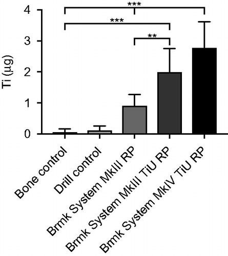
Compared with the machined surface, the TiU implant (Nobel Brmk System MkIII) with the same diameter but different Sa and Sdr values, showed a higher amount of Ti released, 2.00 ± 0.56 µg, 95% CI (1.6–2.4 ; p = .001), but no difference compared to the TiU (MkIV) with the wider diameter (p = .5). Control (un-burred) samples and prepared (burred) bone showed very low content of Ti, mean 0.06 ± 0.11 µg, 95% CI (−0.02–0.14) and 0.11 ± 0.15 µg, 95% CI (0–0.22), respectively and the difference was not significant (p = 1; ).
The null hypothesis could be rejected.
3.2 SEM analysis of the implant surface
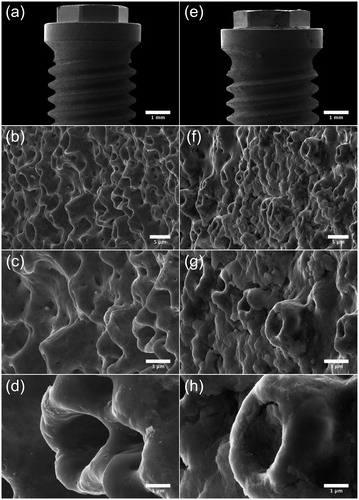
Micrographs acquired by SEM show the surface topography of the machined () and TiUnite surface (). Notable is that the machined surface has two different surface structures, one rougher on the sides of the threads, where deeper grooves from the turning instrument can be seen compared to the area between and on the edge of the threads with a smoother structure ()). At higher magnifications, sharp edges of the grooves with visible extruding metal fragments can be seen at the machined surface ()). Micrographs of the TiUnite surface show a very regular pattern of pores, elevations, depressions and pits of the anodized surface, which gives the surface enlargement. Sharp edges as seen at the machined surface are not visible at the anodized surface. Micrographs acquired after insertion of the implant into the bone show totally different pattern between the two investigated surfaces (Figure and ). Biological material is visible at the machined surface, but in a much less content compared to the anodized surface. At the TiUnite surface, bone material can be seen covering the surface and into the depressions and pits. No clearly visible damages to the surfaces are seen at either the machined or the TiUnite surface after placement into the bone.
Figure 4. SEM micrographs illustrating the morphology of Brmk System MkIII machined surface. (a) Overview of the top of an Brmk System MkIII machined implant (original magnification 30 X). (b–d) The surface structure differs on sides of the threads, there deeper grooves in the implant surface after the turning instrument can be seen, compared to the edges and between the threads a smoother surface can be seen. Higher magnification of the rougher part on the sides of the threads showing the irregularities of the surface structure, with grooves and some protruding metal fragments (original magnification is (b) 200 X, (c) 10 kX and (d) 50 kX). (e) Overview of the top of an Brmk System MkIII machined implant after insertion into the bone (original magnification 30 X). (f–h) Biological material can be seen on the surface of the implant. No obvious damages to the surface can be seen in higher magnifications after insertion into the bone. Biological material is clearly visible on the surface (original magnification is (f) 200 X, (g) 10 kX and (h) 50 kX).
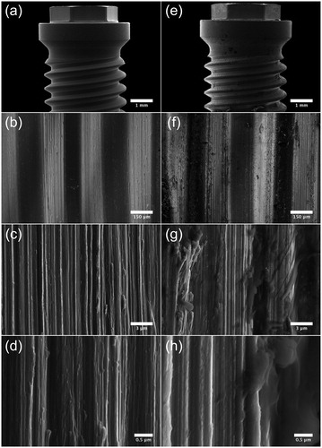
Figure 5. SEM micrographs illustrating the morphology of Brmk System MkIII TiUnite surface. (a) Overview of the top of an Brmk System MkIII TiUnite implant (original magnification 30 X). (b–d) Anodized surface with elevations, depressions and pits, which is rougher than the machined surface and gives the implant a surface enlargement (original magnification is (b) 5, (c) 10 and (d) 30 kX, respectively). (e) Overview of the top Brmk System MkIII TiUnite implant after insertion into the bone (original magnification 30 X). (f–h) In higher magnification, it is clearly visible that the TiUnite surface is covered with biological material after insertion. Bone are visible in the elevations, depressions and pits, but no obvious damages to the surface can be seen. (original magnification is (f) 5, (g)10 and (h) 30 kX, respectively).
3.3 Correlation analysis, to investigate which factor of implant design (total implant-bone area, surface roughness or diameter) is the most important factor concerning release of Ti during insertion of an implant
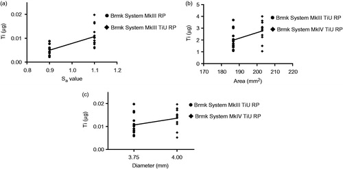
Linear regression analysis showed a positive correlation (r2 = 0.457, p < .001) between surface roughness (Sa) for the 3.75 mm diameter implants with a machined surface vs. the TiU surface in terms of Ti released to the bone (). Total implant-bone area showed a weak correlation (r2 = 0.200, p = .020) (), while implant diameter showed no correlation (r2 = 0.121, p = .076) for the amount of Ti found in the bone during insertion ().
Figure 6. Effect of surface roughness, total implant-bone area and implant diameter on titanium (Ti) released into the bone during insertion. (a) Amount of Ti released (µg) from a machined surface compared with a TiUnite surface with the same 3.75 mm diameter and compensations for the bone-implant area made, but different surface roughness Sa = 0.9 vs. 1.1. Statistical analysis with linear regression show a correlation between surface roughness and Ti release, r2 = 0.457, p < .001 (n = 29). (b) Amount of Ti released (µg) from implants with same surface roughness, but different bone-implant area. Linear regression shows a weak correlation between bone-implant area and Ti release, r2 = 0.200, p = .020 (n = 27). (c) Amount of Ti released (µg) from implants with the same surface roughness and compensations for the bone-implant area made, but with different implant diameters, 3.75 vs. 4.0 mm. Linear regression show a no correlation between implant diameter and Ti release, r2 = 0.121, p =.076 (n = 27).
4. Discussion
Previous studies have shown that Ti can be accumulated in the bone adjacent to Ti dental implants [Citation31,Citation32,Citation36,Citation42–45], but contradictory results have been reported of raised systemic levels of Ti from prosthetic implants [Citation46–51]. Quantitative results from the present study confirm these findings from previous studies, that Ti abraded from the implant during insertion can be quantified in the bone samples with ICP-AES analysis.
In addition, surface roughness of the implant markedly increases the content of Ti found in the bone after insertion of an implant. Surface roughness of the implant seems to be the most important factor regarding the amount of Ti found in the bone after insertion. Total bone-implant area and diameter of the drilled implant site seem to be of less importance regarding amount of Ti released from the implant. These findings, agrees with previous reports, showing that a rougher implant surface induce more friction during insertion, which could lead to particle detachment from the implant [Citation43,Citation52,Citation53]. It is well know that variations in surface roughness affect the coefficient of friction [Citation54–56], which gives a higher insertion torque for the implant during insertion [Citation21].
To perform this material test in an in vivo-like model, jaw bone from pigs were chosen, because the bone structure, mineral density and mineral concentration are similar to that in humans [Citation57,Citation58]. In the present study, we could not identify any visible damages to the implant surfaces during insertion with the SEM examination in contrary to Senna et al. [Citation53], who found visible fractures and chipping of the porous structure at the TiUnite surface. Biological material was visible with SEM on both examined surfaces, but in a much higher content on the TiU surfaces. Surface characteristics of the implants correspond with previously published data [Citation59–63].
Quantification of Ti and especially TiO2 can be challenging in biological tissue and to achieve a reliable result all Ti needs to be dissolved. In the present study, we used the combination of HNO3 and HF proposed and validated by Faucher et al. as the best dissolvent for Ti and TiO2 in biological samples [Citation64] in combination with microwave digestion. By this aggressive dissolvent all Ti can be quantified, but if the Ti found was present in the bone as metallic or TiO2 is not possible to determine. No visible damages on the TiUnite surface could be detected with our SEM analyses, which indicate that the origin of the quantified Ti is derived from the surface layer of the implant.
The total amount of Ti (µg) found in the bone samples from the implant sites was measured with ICP-AES analysis in this study. The study design, with a short time between insertion and removal of the implant, as well as the non-vital bone tissue limit opportunities for biological transfer of Ti. Therefore, only the bone in direct contact with the implant during insertion should contain the abraded Ti from the implant. The results show the total amount of Ti (µg) released from each implant during insertion, instead of concentration which could be misleading. Comparison with our quantitative data of Ti content found in the present study with previously published data is difficult to make, as most of the published data of Ti levels are measured in serum and organ tissues where concentration is a preferred measurement [Citation46,Citation48,Citation65,Citation66]. Senna et al. measured the reduction of the surface volume after insertion of a dental implant into bone from cow ribs and calculated the released Ti mathematical by the volume reduction to 0.06 mg for the TiUnite surface, which is 21 times higher than our findings in the present study [Citation53]. Our quantitative data of Ti amount (µg) in the bone after placement of an implant could therefore be used as a reference level in further studies. In a recent study by Safioti et al., they found that levels of Ti was significantly increased in plaque from peri-implantitis compared to healthy patients and concluded, that the results indicate an association between titanium dissolution and peri-implantitis [Citation37].
Albrektsson et al. proposed that peri-implantitis is a foreign body reaction against the implant [Citation67] and in orthopedic research osteolysis due to immunological reactions against particles debris is well known [Citation68–70]. We have previously shown that Ti in combination with liposaccharides (LPS) from E. coli induce a pro-inflammatory response in human macrophages [Citation27]. Similar results have been published by other authors with endothelial cells; they conclude that a Ti concentration >11 ppm can induce tissue necrosis and that a Ti concentration of 5 ppm in combination with LPS can cause an inflammatory response [Citation28]. Ti added to unstimulated cells do not activate release of IL-1β, which indicates that this effect of Ti is of biological relevance only in already inflamed tissues [Citation27].
The model used in the present study seems to be an easy way to quantify the amount of Ti abraded from a dental implant during insertion.
A limitation of the present study is that the interesting biological process in an inflamed tissue that can cause further release of Ti cannot be studied in this model. But it is interesting, that such high amount of Ti could be quantified in the bone after insertion of a dental implant and the effect of the released Ti should be further studied.
However, the release of Ti during installation of an implant may be a factor of importance for the inflammatory process in peri-implant tissue.
In conclusion, we show that Ti is abraded to the surrounding bone upon insertion of a dental implant. The surface structure of the implant is important for the amount of Ti released, while total area and diameter of the implant are of less importance.
Acknowledgements
The authors thank Nobel Biocare for donation of the implants, implant images and their help with area measurements for this study. A special thanks to Cheng Choo Lee at Umeå Core Facility for Electron Microscopy (UCEM), Umeå University for the help with electron microscopy.
Disclosure statement
No potential conflict of interest was reported by the authors.
Additional information
Funding
References
- Long M, Rack HJ. Titanium alloys in total joint replacement-a materials science perspective]. Biomaterials. 1998;19:1621–1639.
- Geetha M, Singh AK, Asokamani R, et al. Ti based biomaterials, the ultimate choice for orthopaedic implants – a review [Review]. Prog Mater Sci. 2009;397–425.
- Niinomi M. Mechanical biocompatibilities of titanium alloys for biomedical applications [Review]. J Mech Behav Biomed Mater. 2008;1:30–42.
- Branemark PI, Adell R, Breine U, et al. Intra-osseous anchorage of dental prostheses. I. Experimental studies. Scand J Plast Reconstr Surg Hand Surg. 1969;3:81–100.
- Brånemark PI, Zarb GA, Albrektsson T. Tissue-integrated prostheses: osseointegration in clinical dentistry. Chicago: Quintessence Publ. Co. Inc.; 1985. (Quintessence books).
- Brunette DM. Titanium in medicine: material science, surface science, engineering, biological responses and medical applications. Berlin: Springer; 2001.
- Steinemann SG. Titanium-the material of choice? Periodontol 2000. 1998;17:7–21.
- Jong WHD, Krystek P, Nia Y, et al. WP7: toxicokinetics and tissue distribution of MNs for specification of organs at risk for genotoxicity testing. Anses Faff, environmental and occupational health safety, editor, Marc Mortureux, Director General of ANSES; 2013. Available from: Nanogenotox.eu
- Liu XY, Chu PK, Ding CX. Surface modification of titanium, titanium alloys, and related materials for biomedical applications. Mater Sci Eng R-Rep. 2004;47:49–121.
- Branemark PI, Hansson BO, Adell R, et al. Osseointegrated implants in the treatment of the edentulous jaw. Experience from a 10-year period. Scand J Plast Reconstr Surg Suppl. 1977;16:1–132.
- Adell R, Eriksson B, Lekholm U, et al. Long-term follow-up study of osseointegrated implants in the treatment of totally edentulous jaws. Int J Oral Maxillofac Implants. 1990;5:347–359.
- Lindquist LW, Carlsson GE, Jemt T. A prospective 15-year follow-up study of mandibular fixed prostheses supported by osseointegrated implants. Clinical results and marginal bone loss [Article]. Clin Oral Implants Res. 1996;7:329–336.
- Bornstein MM, Lussi A, Schmid B, et al. Early loading of nonsubmerged titanium implants with a sandblasted and acid-etched (SLA) surface: 3-year results of a prospective study in partially edentulous patients. Int J Oral Maxillofac Implants. 2003;18:659–666.
- Cochran DL, Jackson JM, Bernard JP, et al. A 5-year prospective multicenter study of early loaded titanium implants with a sandblasted and acid-etched surface. Int J Oral Maxillofac Implants. 2011;26:1324–1332.
- Cannizzaro G, Leone M, Consolo U, et al. Immediate functional loading of implants placed with flapless surgery versus conventional implants in partially edentulous patients: a 3-year randomized controlled clinical trial. Int J Oral Maxillofac Implants. 2008;23:867–875.
- Polizzi G, Gualini F, Friberg B. A two-center retrospective analysis of long-term clinical and radiologic data of TiUnite and turned implants placed in the same mouth. Int J Prosthodont. 2013;26:350–358.
- Kokovic V, Jung R, Feloutzis A, et al. Immediate vs. early loading of SLA implants in the posterior mandible: 5-year results of randomized controlled clinical trial. Clin Oral Impl Res. 2014;25:e114–e119.
- Pimentel Lopes de Oliveira GJ, Leite FC, Pontes AE, et al. Comparison of the primary and secondary stability of implants with anodized surfaces and implants treated by acids: a split-mouth randomized controlled clinical trial. Int J Oral Maxillofac Implants. 2016;31:186–190.
- Morris HF, Ochi S, Orenstein IH, et al. AICRG, Part V: factors influencing implant stability at placement and their influence on survival of Ankylos implants. J Oral Implantol. 2004;30:162–170.
- Roccuzzo M, Aglietta M, Bunino M, et al. Early loading of sandblasted and acid-etched implants: a randomized-controlled double-blind split-mouth study. Five-year results. Clinical Oral Implants Research. 2008;19:148–152.
- Dos Santos MV, Elias CN, Cavalcanti Lima JH. The effects of superficial roughness and design on the primary stability of dental implants. Clin Implant Dent Relat Res. 2011;13:215–223.
- Wennerberg A, Albrektsson T. Suggested guidelines for the topographic evaluation of implant surfaces. Int J Oral Maxillofac Implants. 2000;15:331–344.
- Wennerberg A, Albrektsson T, Lausmaa J. Torque and histomorphometric evaluation of c.p. titanium screws blasted with 25- and 75-microns-sized particles of Al2O3. J Biomed Mater Res. 1996;30:251–260.
- Wennerberg A, Albrektsson T, Andersson B. An animal study of c.p. titanium screws with different surface topographies [Article]. J Mater Sci Mater Med. 1995;6:302–309.
- Albrektsson T, Wennerberg A. Oral implant surfaces: part 1-review focusing on topographic and chemical properties of different surfaces and in vivo responses to them. Int J Prosthodont. 2004;17:536–543.
- Leach R. Characterisation of areal surface texture. Berlin, Heidelberg: Springer Berlin Heidelberg; 2013.
- Pettersson M, Kelk P, Belibasakis GN, et al. Titanium ions form particles that activate and execute interleukin-1β release from lipopolysaccharide-primed macrophages. J Periodont Res. 2017;52:21–32.
- Makihira S, Mine Y, Nikawa H, et al. Titanium ion induces necrosis and sensitivity to lipopolysaccharide in gingival epithelial-like cells [Research Support, Non-U.S. Gov’t]. Toxicol In Vitro. 2010; 24:1905–1910.
- Makihira S, Mine Y, Kosaka E, et al. Titanium surface roughness accelerates RANKL-dependent differentiation in the osteoclast precursor cell line, RAW264.7. Dent Mater J. 2007;26:739–745.
- Wachi T, Shuto T, Shinohara Y, et al. Release of titanium ions from an implant surface and their effect on cytokine production related to alveolar bone resorption. Toxicology. 2015;327:1–9.
- Schliephake H, Reiss G, Urban R, et al. Metal release from titanium fixtures during placement in the mandible: an experimental study. Int J Oral Maxillofac Implants. 1993;8:502–511.
- Meyer U, Buhner M, Buchter A, et al. Fast element mapping of titanium wear around implants of different surface structures. Clin Oral Implants Res. 2006;17:206–211.
- Noguti J, de Oliveira F, Peres RC, et al. The role of fluoride on the process of titanium corrosion in oral cavity. Biometals. 2012;25:859–862.
- Boere G. Influence of fluoride on titanium in an acidic environment measured by polarization resistance technique. J App Biomater. 1995;6:283–288.
- Mathew MT, Abbey S, Hallab NJ, et al. Influence of pH on the tribocorrosion behavior of CpTi in the oral environment: synergistic interactions of wear and corrosion. J Biomed Mater Res Part B Appl Biomater. 2012;100:1662–1671.
- He X, Reichl FX, Wang Y, et al. Analysis of titanium and other metals in human jawbones with dental implants – a case series study. Dent Mater. 2016;32:1042–1051.
- Safioti LM, Kotsakis GA, Pozhitkov AE, et al. Increased levels of dissolved titanium are associated with peri-implantitis – a cross-sectional study. J Periodontol. 2017;88:436–442.
- Sul YT, Johansson CB, Petronis S, et al. Characteristics of the surface oxides on turned and electrochemically oxidized pure titanium implants up to dielectric breakdown: the oxide thickness, micropore configurations, surface roughness, crystal structure and chemical composition. Biomaterials 2002;23:491–501.
- Everhart TE, Thornley RFM. Wide-band detector for micro-microampere low-energy electron currents. J Sci Instrum. 1960;37:246–248.
- Kruskal WH, Wallis WA. Use of ranks in one-criterion variance analysis. J Am Stat Assoc. 1952;47:583–621.
- Dunn OJ. Multiple comparisons using rank sums. Technometrics. 1964;6:241–252.
- Tanaka N, Ichinose S, Kimijima Y, et al. Investigation of titanium leak to bone tissue surrounding dental titanium implant: electron microscopic findings and analysis by electron diffraction. Med Electron Microsc. 2000;33:96–101.
- Martini D, Fini M, Franchi M, et al. Detachment of titanium and fluorohydroxyapatite particles in unloaded endosseous implants. Biomaterials. 2003;24:1309–1316.
- Flatebo RS, Hol PJ, Leknes KN, et al. Mapping of titanium particles in peri-implant oral mucosa by laser ablation inductively coupled plasma mass spectrometry and high-resolution optical darkfield microscopy. J Oral Pathol Med. 2011;40:412–420.
- Franchi M, Orsini E, Martini D, et al. Destination of titanium particles detached from titanium plasma sprayed implants. Micron. 2007;38:618–625.
- Sarmiento-Gonzalez A, Encinar JR, Marchante-Gayon JM, et al. Titanium levels in the organs and blood of rats with a titanium implant, in the absence of wear, as determined by double-focusing ICP-MS. Anal Bioanal Chem. 2009;393:335–343.
- Rodriguez D, Gil FJ, Planell JA, et al. Titanium levels in rats implanted with Ti6Al4V treated samples in the absence of wear. J Mater Sci Mater Med. 1999;10:847–851.
- Bianco PD, Ducheyne P, Cuckler JM. Systemic titanium levels in rabbits with a titanium implant in the absence of wear. J Mater Sci Mater Med. 1997; 8:525–529.
- Lee S, Goh BT, Lai SH, et al. Peri-implant and systemic release of metallic elements following insertion of a mandibular modular endoprosthesis in Macaca fascicularis. Acta Biomaterialia. 2009;5:3640–3646.
- Frisken KW, Dandie GW, Lugowski S, et al. A study of titanium release into body organs following the insertion of single threaded screw implants into the mandibles of sheep. Aust Dent J. 2002;47:214–217.
- Weingart D, Steinemann S, Schilli W, et al. Titanium deposition in regional lymph nodes after insertion of titanium screw implants in maxillofacial region. Int J Oral Maxillofac Surg. 1994;23:450–452.
- Franchi M, Bacchelli B, Martini D, et al. Early detachment of titanium particles from various different surfaces of endosseous dental implants. Biomaterials. 2004;25:2239–2246.
- Senna P, Antoninha Del Bel Cury A, Kates S, et al. Surface damage on dental implants with release of loose particles after insertion into bone. Clin Implant Dent Relat Res. 2015;17:681–692.
- Rancourt D, Shirazi-Adl A, Drouin G, et al. Friction properties of the interface between porous-surfaced metals and tibial cancellous bone. J Biomed Mater Res. 1990;24:1503–1519.
- Dammak M, Shirazi-Adl A, Schwartz M Jr, et al. Friction properties at the bone-metal interface: comparison of four different porous metal surfaces. J Biomed Mater Res. 1997;35:329–336.
- Biemond JE, Aquarius R, Verdonschot N, et al. Frictional and bone in-growth properties of engineered surface topographies produced by electron beam technology. Arch Orthop Trauma Surg. 2011;131:711–718.
- Aerssens J, Boonen S, Joly J, et al. Variations in trabecular bone composition with anatomical site and age: potential implications for bone quality assessment. J Endocrinol. 1997;155:411–421.
- Mosekilde L, Kragstrup J, Richards A. Compressive strength, ash weight, and volume of vertebral trabecular bone in experimental fluorosis in pigs. Calcif Tissue Int. 1987;40:318–322.
- Svanborg LM, Andersson M, Wennerberg A. Surface characterization of commercial oral implants on the nanometer level. J Biomed Mater Res Part B Appl Biomater. 2010;92:462–469.
- Kang BS, Sul YT, Oh SJ, et al. XPS, AES and SEM analysis of recent dental implants. Acta Biomater. 2009;5:2222–2229.
- Jarmar T, Palmquist A, Branemark R, et al. Characterization of the surface properties of commercially available dental implants using scanning electron microscopy, focused ion beam, and high-resolution transmission electron microscopy. Clin Implant Dent Rel Res. 2008;10:11–22.
- Liu R, Lei T, Dusevich V, et al. Surface characteristics and cell adhesion: a comparative study of four commercial dental implants. J Prosthodont. 2013;22:641–651.
- Aparicio C, Olive J. Comparative surface microanalysis of failed Branemark implants. Int J Oral Maxillofac Implants. 1992;7:94–103.
- Faucher S, Lespes G. Quantification of titanium from TiO2 particles in biological tissue. J Trace Elem Med Biol. 2015;32:40–44.
- Balcaen L, Bolea-Fernandez E, Resano M, et al. Accurate determination of ultra-trace levels of Ti in blood serum using ICP-MS/MS. Anal Chim Acta. 2014;809:1–8.
- Levine BR, Hsu AR, Skipor AK, et al. Ten-year outcome of serum metal ion levels after primary total hip arthroplasty: a concise follow-up of a previous report. J Bone Joint Surg Am. 2013;95:512–518.
- Albrektsson T, Dahlin C, Jemt T, et al. Is marginal bone loss around oral implants the result of a provoked foreign body reaction? Clin Implant Dent Relat Res. 2014;16:155–165.
- Harris WH, Schiller AL, Scholler JM, et al. Extensive localized bone resorption in the femur following total hip replacement. J Bone Joint Surg Am. 1976;58:612–618.
- Jacobs JJ, Skipor AK, Patterson LM, et al. Metal release in patients who have had a primary total hip arthroplasty. A prospective, controlled, longitudinal study. J Bone Joint Surg Am. 1998;80:1447–1458.
- Hallab NJ, Jacobs JJ. Chemokines associated with pathologic responses to orthopedic implant debris. Front Endocrinol (Lausanne). 2017;8:5.
- Wennerberg A, Albrektsson T. On implant surfaces: a review of current knowledge and opinions. Int J Oral Maxillofac Implants. 2010;25:63–74.