
 ?Mathematical formulae have been encoded as MathML and are displayed in this HTML version using MathJax in order to improve their display. Uncheck the box to turn MathJax off. This feature requires Javascript. Click on a formula to zoom.
ABSTRACT
Centrifugal pumps consume the equivalent of one fifth of the total energy consumption around the world. Also, increasing the requirement for fresh water negatively affects water levels from its various sources such as rivers, canals, and groundwater. As normal, this reduces the possibility of normal operation of some pump stations, and usually, this occurs as a result of the low suction level for these stations. Moreover, some other pump stations are affected by its operation efficiency i.e. decreases performance quality, each according to the value of the suction level decreasing. Therefore, the most effect parameter on the pump performance at the suction side of the centrifugal pump is defined as the Net Positive Suction Head (NPSH). However, using inducer at the suction side of the operating pump can improve its performance. Thus, the behavior of NPSH and the total performance of a centrifugal pump are experimentally and numerically studded. In addition to, the NPSH performance is determined using the NPSH test and improved by 3% at 2900 rpm with using the inducer at the operating point, and the performance of the pump is monitored at the low and high discharges value.
Introduction and literature review
Turbomachines produce a centrifugal effect to increase the fluid pressure, for more than a century, which have been in use. The first machines that use this principle were, undoubtedly, hydraulic pumps followed later by blowers and ventilating fans (Dixon & Eng, Citation1998). Centrifugal pumps consume the equivalent of 20% (Aboelnil, Abdellatif, Shahin, Moawad, & Abd Rabbo, Citation2019) of the total energy consumption around the world. They consist essentially of a rotating impeller followed by volute case. Fluid passes through the inlet casing to the eye of the impeller. The impeller function is whirling the fluid outward, which increases the amount of angular momentum. The velocity and static pressure are increased according the rotation of the impeller. The function of the volute is to convert the fluid kinetic energy, which leave the impeller, into pressure energy. At the design stage, the inlet eye is very important critical region in centrifugal pumps, which require careful consideration. When the static pressure going through the inlet eye, is too small, cavitation may result with consequently erosion on the blades also the performance is reduce. Furthermore, cavitation may be defined as the boiling of liquid at normal temperature when the static pressure is low enough. This may occur at the pumps entry or at the exit from hydraulic turbines near and around the moving blades. However, Net Positive Suction Head (NPSH) is defined as the amount of suction head needed to avoid cavitation. According the water scarcity and rivers levels depression, the working pump stations normally face so critical problem, which represented in the reduction of the available Net Positive Suction Head (NPSH). Now, if the inducer could be installed before the eye-inlet of an impeller, then the increasing of velocity, static pressure, and NPSH became reality. In addition to, the axial gap between the inducer and impeller is reduced to 3 percent of the impeller diameter. In the same time, the head coefficient of the pump decreased by about 2%, which can be attributed to interference between inducer and impeller (LI, Wang, Fu, & Fu, Citation2007). Adding an inducer to the pump inlet could mainly improve the pump cavitation performance. Furthermore, the long equal pitch inducer introduced the best cavitation performance, whereas the second is the progressive pitch inducer; also, the third is the device with two long and two short inducers, and the last is the equal pitch inducer, (Xiaomei, Zuchao, Baoling, & Yi, Citation2012). The inducer has a negligible effect on the head and efficiency of the pump, but a significant effect on the cavitation performance. The critical NPSH of the pump increases more than three times when the pump is tested without the inducer (Soon-Sam, Dae-Jin, Jin-Sun, Chang-Ho, & Jinhan, Citation2012). Maximum efficiency and higher performance of the Centrifugal pump are obtained by using helical inducer (2 turns (17°)), shaft diameter 25 mm in all case studies of inducers (helical–axial), and it is preferable to be used for having the best performance of the centrifugal pump (El Samanody, Ashraf, & Mamdoh, Citation2014; Hawash, El-Gazzar, & El Samanody, Citation2015). The static pressure is increased on both the inducer and the impeller, with the increase of the rotational speed also the lowest static pressure on the impeller under similar operational conditions is decreased with the increase of the rotational speed. Therefore, the anti-cavitation performance of the pump is deteriorated with the increase of the rotational speed (Xiaomei, Zuchao, Baoling, & Yi, Citation2017). The rotor-dynamic forces acting on a space turbo-pump composed by an axial inducer and a radial impeller have been measured at three different flow coefficients in cavitation and non-cavitation conditions (Giovanni et al., Citation2016).
The present work
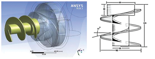
In the present study, the performance of a centrifugal pump Q-H, efficiency, power, and NPSH curves is studied experimentally using a laboratory test rig with and without using inducer before the suction side of the impeller. The inducer that is used in the present study is helical type with 2 turn 20 degree of twist as references (El Samanody et al., Citation2014) and (Hawash et al., Citation2015). Also, the numerical model for the pump for two cases is generated using CFD to deeply investigate the changing of all factors, which effected on the pump performance.
Experimental study
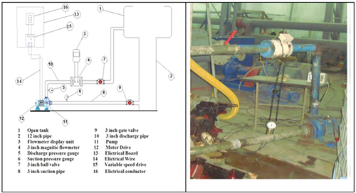
The plant for the investigation of centrifugal pumps is shown schematically and photographically in . It consists of a closed cycle and is operated with water of ambient temperature. The open water store tank is made of steel with size maximally 1 cubic meter and is provided with several pipe unions as well as a level monitoring and an exhaust. The suction pipe of the nominal size (DN) 90 (measured inside Diameter di = 82.5 mm). In the pressure pipe of the nominal size DN 90 (di = 82.5 mm), a flat slide is inserted behind the pump, which serves as shutoff device. Subsequently, an extension of the pressure pipe DN 90 as well as a regulating valve DN 90 follows. With its assistance the operating point of the pump can be adjusted. Magnetic flow meter with 90 mm diameter and precision 0.001 is used for investigate the flow discharge, two pressure sensor are put up at the suction with range −1 to 1 bar and discharge side with range 0–5 bar, variable speed drive also is installed to vary the frequency for investigate the performance at different rotation speed, and the power meter is used to measure the input electrical factors such as volt, ampere, and consuming power.
Testing method and procedures
Measurement of the characteristics of a centrifugal pump includes the taking down of a throttle curve at a certain number of revolutions as well as a number of revolutions characteristic during a certain throttle position. Apart from the machine characteristics also only for the throttle curve, the delivery head characteristics of the individual stages are to be determined and to be represented in the prepared diagrams.
Performance or (H–Q) curve procedures
The pump is allowed to operate a few minutes before taking any data. During this time period, the discharge valve is opened and closed to observe the suction and discharge pressure sensors. At affixed rotation speed, the head of the pump is varied by gradually opening the discharge valve over several increments until the discharge valve is fully closed. At each increment, including the fully closed initial discharge valve position, all factors of measurement are recorded such as flow capacity, pressure, input power, and RPM. At each recorded, the following equations are used to calculate the total head and overall efficiency of the pump(Equationequation (1)(1)
(1) and Equation(2))
(2)
(2) .
Where;
Ps and Pd: are the pressure values at the suction and delivery side respectively.
Vs and Vd: are the velocity at the suction and delivery side.
Zs and Zd: are the static head at suction and delivery side.
Hloss: is the head loss due to test.
Wp: is output water power (ρ g Q H).
E.p: is the measured input power by Kw.
ρ: is the density (kg/m3) of fluid, g is normal acceleration (m2/s).
Q: is discharge m3, and H is the total head in m.
Net Positive Suction Head (NPSH) curve procedures
According to reference 1, cavitation appears when the available NPSH is equal to the required NPSH and considered at 3% drop in the total head at a certain point, so the system must be prepared to reach this state by reducing the inlet pressure using throttle suction valve to reach 3% drop at total head until these case the available NPSH; Equationequation (3)(3)
(3) is used to calculate the required NPSH.
Where
: is the blade cavitation coefficient and lies in range 0.2 to 0.4 (Dixon & Eng, Citation1998),
Pv: is the vapor pressure at the inlet,
ρ: is the density of the fluid, and
W1: is the absolute velocity at the inlet of the impeller.
Experimental results
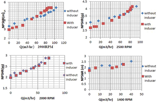
The performance of the centrifugal pump is investigated at different RPM values, 2900, 2500, 2000, and 1400, The effect of the inducer is clearly shown in the performance during changing of RPM values. At 2900 RPM, the improving of total head is only at small amount of the discharge values and became to collapse even the discharge increase, at discharge 10 m3/hr the improving of total head was 4%, and the total head is decreasing by 6% when using inducer at 90 m3/hr. This collapsing is reduced during the RPM is changed to 2500, and the curve became smoothly with changing the discharge amount; at discharge 10 m3/hr, the improving of total head was 5.5% and the total head is decreasing by 1% when using inducer at 90 m3/hr. But the total head convert its performance during RPM 2000 and effect of the inducer is clearly going to be improved during all points of the discharge, the improving became about 13% to 1% and the same effect at 1400 RPM, but the amount of improving is increasing about 20% to 3%. The reason of the changing in performance according different RPM values is the friction affect during the flow entrance the suction pipe of the pump. The friction according impact of flow with the inducer surface increase with increasing the impact velocity, so the friction is affected by the two velocity parameters the first one is the RPM of the inducer and second is the inlet flow velocity. The following shows the installation of the inducer at the inlet of the pump. The effect of the velocities and the friction also are shown in the estimated efficiency curves according the change of RPM values. The previous scenario is repeated, and the effect of the velocity occurs also in the efficiency in the same direction, which the efficiency improves with decreasing the velocities of the flow and rotation, as shown in All quantity of efficiencies is dropped with decreasing the rotational speed of the pump because of the best operating condition for the pump is at 2900 rpm. The important factor, which the inducer is used, is the required net positive suction head (NPSHR) also investigates. The affecting of using inducer occurs in positive direction, which the goal is decreasing the required net positive suction head. When the inducer is used NPSHR is decreased along all point of the test except some point at 2900 RPM and high values of discharge, which the highest effect of the friction, as shown in The NPSHR improve by 3%, 4%, 4%, and 5% at the operating point and 2900, 2500, 2000, and 1400 RPM, respectively. Increasing the velocity and the pressure of the flow enter the pump by using the inducer improve the suction performance of the centrifugal pump and reduce the required net positive suction head which avoid cavitation.
Figure 2. Q-H Curve at Different RPM Values
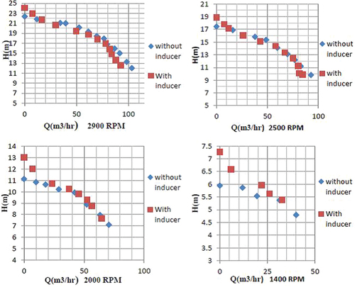
Figure 3. Inducer Set at Inlet Of The Pump
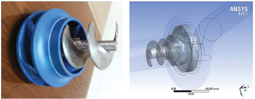
Figure 4. Curves Of Efficiency at Different RPM Values
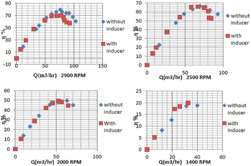
Figure 5. NPSH Curves at Different RPM
Numerical model
A complete three dimensional model for the pump with and without inducer is designed and generated. The design model consists of different parts. First, the main part is the impeller which has complicate design shapes. The program CFTURBO can draw the impeller blades shape, hub and shroud surfaces using the design equation in reference (Aboelnil et al., Citation2019). Second, the volute casing also is drawn using the same program. Finally, the inlet and discharge pipe which designed according the suction and discharge diameters of the centrifugal pump. All dimensions and design parameters are compared with the original pump sited in the test rig and have the same dimensional. Inducer is also designed and drawn using ANSYS Ver. 18.1, design modeler program according the choice shape which a helical two turn inducer with outer diameter equal the suction diameter of the pump. The complete 3D model of the pump and inducer with dimensional is shown in Automatic mesh is generated using CFD program. The program can refine the quality of the generated mesh and choose the perfect type of mesh for each zone. The final total node of the mesh is 500000 nodes which is the good amount of nodes according references (Bacharoudis, Filios, Mentzos, & Margaris, Citation2008; Pandey, Singh, & Sujoy, Citation2012). Fluent is used to estimate the inner flow field of the model. Incompressible flow during the rotating impeller with fixed and rotation frame case is chosen to solve the NAVIR-STOCK Equationequations (4(4)
(4) ), by standard k-ε turbulence model and SIMPLEC algorithm which the best type for the pump model (Aboelnil et al., Citation2019). Inlet and outlet mass flow boundary condition for the model is determined and interface boundary between the fixed and rotated zone is estimated.
Figure 6. 3D Pump and Inducer Model
Where
P: is the static pressure,
Ur; is the vector fluid velocity in the rotating system,
Ω: is the rotational speed, and
Μeff: is the dynamic effective viscosity.
Main results of numerical study
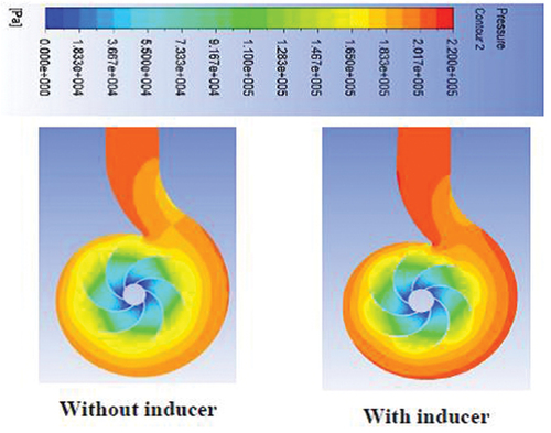
The velocity distribution showed the main different of model results with and without inducer. The effect of using the inducer is shown clearly on changing values of the impeller entrance velocities that changed from 2–3 m/s (with inducer) to 6–9 m/s (without inducer). This increasing of velocities effect immediately, on the pump performance which is accompanied with friction increasing (between the flow and the inducer surface). However, the improving in the performance depends normally on velocities of both the impeller and flow. Then, shows the velocity distribution in two cases with and without using inducer. The effect of using inducer also is presented by the static pressure distribution, which showed the improving of the static pressure during the inner flow field of both the impeller and volute. The velocity increasing of the flow enters the impeller improve the static pressure; this happened at the flow leaves the impeller then inlet the volute case. Addition to, this static pressure actually increased by 2% with using the inducer, as shown in
Figure 7. Velocity Distribution at Inlet With and Without Inducer
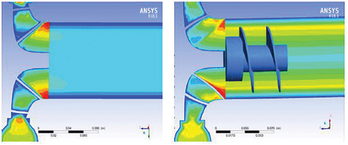
Figure 8. Static Pressure Contour
Conclusion
The effect of using inducer with a centrifugal pump is studied experimentally and numerically at different rotational speeds. The performance of the centrifugal pump is affected by using the inducer according the inlet flow velocity and the rotational speed of the pump. At high rotational speeds and discharges, the performance of the pump is not improved, but when the rotational speed decreased to 2000 and 1400 rpm, the performance is improved up to 20%. Otherwise, the net positive suction head is improved by 3% at the operating point of 2900 RPM experimentally. A complete three dimensional mathematical model is constructed using CFD to obtain the performance of the pump with and without inducer. The velocity and pressure contour is discussed which agree with the experimental results.
Disclosure statement
No potential conflict of interest was reported by the author(s).
References
- Aboelnil, A. H. I., Abdellatif, M. A., Shahin, I., Moawad, M. A., & Abd Rabbo, M. F. (2019). Performance and slip factor prediction for radial and mixed flow pumps. International Journal of Scientific and Engineering Research, 10(7), 2229–5518.
- Bacharoudis, E. C., Filios, A. E., Mentzos, M. D., & Margaris, D. P. (2008). Parametric study of a centrifugal pump impeller by varying the outlet blade angle. The Open Mechanical Engineering Journal, 2(1), 75–83. doi:10.2174/1874155X00802010075
- Dixon, S. L., & Eng, B., (1998). Fluid Mechanics and Thermodynamics of Turbomachinery fourth edition. Butterworth-Heinemann A member of the Reed Elsevier Group.
- El Samanody, M. A., Ashraf, G., & Mamdoh, A. M. (2014). Investigations on the performance of centrifugal pumps in Conjunction with inducers. Ain Shams Engineering Journal, 5(1), 149–156. doi:10.1016/j.asej.2013.07.003
- Giovanni, P., Valentini, D., Angelo, P., Lucio, T., Ruzbeh, H., & Luca, D. A., (2016, April 10-15). Inducer and Centrifugal Pump Contributions to the Rotordynamic Fluid Forces Acting on a Space Turbopump. International Symposium on Transport Phenomena and Dynamics of Rotating Machinery, Hawaii, Honolulu.
- Hawash, S. A. F., El-Gazzar, D. M. S., & El Samanody, M. A. (2015). Reliability improvements to centrifugal pump performance in conjunction with inducers, CFD comparative study. Journal of Earth Science and Engineering (JESE), 5, 296–305. 2159-581X, S. No. 44, David Publishing Comp., U.S.A.
- LI, Y., Wang, J., Fu, J., & Fu, J. (2007). numerical investigation of performance of an axial-flow pump with inducer. Journal of Hydrodynamics, 19(6), 705–711. doi:10.1016/S1001-6058(08)60007-4
- Pandey, K. M., Singh, A. P., & Sujoy, C. (2012). Numerical studies on effects of blade number variations on performance of centrifugal pumps at 2500 rpm. Journal of Environmental Research and Development, 6, 3A.
- Soon-Sam, H., Dae-Jin, K., Jin-Sun, K., Chang-Ho, C., & Jinhan, K. (2012). Study on inducer and impeller of a centrifugal pump for a rocket engine turbopump. Journal of Mechanical Engineering Science. doi:10.1177/0954406212449939
- Xiaomei, G., Zuchao, Z., Baoling, C., & Yi, L., (2012), Analysis of Cavitation Performance of Inducers, the laboratory of fluid transmission and application Zhejiang science technology university China. In Tech.
- Xiaomei, G., Zuchao, Z., Baoling, C., & Yi, L. (2017). Effects of rotational speeds on the performance of a centrifugal pump with a variable-pitch inducer. Journal of Hydrodynamic, 29(5), 854–862. doi:10.1016/S1001-6058(16)60797-7