
 ?Mathematical formulae have been encoded as MathML and are displayed in this HTML version using MathJax in order to improve their display. Uncheck the box to turn MathJax off. This feature requires Javascript. Click on a formula to zoom.
ABSTRACT
In the present time, the Ministry of Water Resources and Irrigation starts to construct new barrages across the Nile River and the main canals to replace the oldest ones, which are not able to withstand the requirements of increasing head difference between the upstream and downstream water levels upon the gates. This paper is focused on investigating experimentally the flow characteristics downstream the vertical sluice gates of Bahr Yousef regulator in case of flow over gate and flow under gate and the proper design for stilling basin with high efficiency in dissipation of water energy downstream the vertical gate with low cost. In the present study experimental work was carried out on a 2-D flume with 1.0 m wide, 26.0 m long, and 1.2 m deep, with discharges range from 22 to 395 l/s at the Hydraulics Research Institute laboratory. This experiment is physically based with scale 1:8.5. The experimental tests involved the observations and measurements of hydraulic phenomena in one single bay of the regulator in case of flow under/over gate. In these tests, there was a group of variables such as; the gate opening, flow rate, pressure head, upstream and downstream water levels, number of gates opening, and D50 of riprap protection. The influence of these parameters on downstream flow characteristics and the rip-rap size was investigated downstream the stilling basin. Comparative analysis between flow under the gate and flow over the gate was carried out. The results showed that the case of flow under gate gave more normal velocity distribution with low turbulent and high efficiency in dissipation of water energy downstream the vertical gates, and it was recommended for the operation of the regulator. Also, the obtained results showed that the size of riprap protection with D50 equal 0.2 m are stable, economic, and reduced the stilling basin length.
Introduction
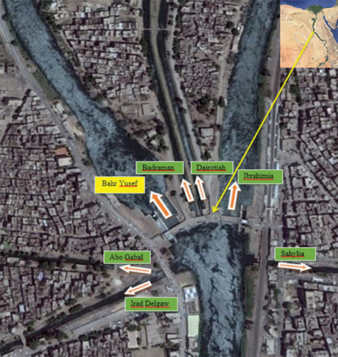
Regulators with sluice gates were very common water structures for controlling discharge in irrigation canals and rivers. In addition to controlling and managing function, they are also used to measure the flow rate in a canal providing a constant head of water to maintain a continuous flow. When the sluice gate height exceeds some design criteria then double or triple leaf gates are provided (Negm, Alhamid, & El-Saiad, Citation1995). This gate moved within a vertical groove incised between two piers, this type of gate was commonly used for barrages. New barrages are constructed on the River Nile instead of the oldest ones, which are not able to resist the requirements of increasing head difference upon their gates (Mohamed, Saleh, & Ali, Citation2015). The flow downstream of the gate is classified as either a free or submerged flow. When the tailwater depth of the flow from a sluice gate is greater than the subcritical sequent depth, the gate outlet is drowned and the jump becomes submerged (Habib Zadeh, Wu, Ade F, Rajaratnam, & Loewen, Citation2011). Submerged hydraulic jump forming downstream of a control structures may produce a vortex having significant countercurrent free surface velocities (Leutheusser & Fan, Citation2001). One of the hydraulic structures that was controlled by gates was regulator. Bahr Yousef regulator as part of the New Dirout Group of Regulators (NDGRs) was selected as case study in this research. shows a layout map for the study area location
Figure 1. Layout of Dirout Group Regulators (DGRs) from Google Earth.
Study Objectives
The aims of this study were as follows. Investigate in detail one bay of the sluice vertical gate in two cases Fully Flow over Gate and Flow under Gate. Studying the case of one closed vent of the vents of regulator and its effect on the flow and on the basin. Negm, A.M. et al. (Negm & El-Saiad, Citation1993) and Demirel, (Demirel, Citation2015) studied about the behavior of submerged flow below vertical gate with sill upstream of horizontal diverging channel. Verifying the proper design for stilling basin with high efficiency in dissipation of water energy currents downstream the vertical gate with low cost. Shayan, Farhoudi (Shayan & Farhoudi, Citation2013) studied the energy loss of free flow under sluice gate. Studying the hydraulic jump characteristics, check the safety of the structure against hydraulic jump. Many previous research studies the hydraulic jump phenomena (Gumus, Simsek, Soydan, Akoz, & Kirkgoz, Citation2016; Ma, Hou, & Prinos, Citation2001). Checking the head losses due to the construction, optimize the stilling basin dimensions. In addition investigate the stability of the rip-rap protection layer downstream the apron.
Experimental work
A well-designed 2D hydraulic physical detail model for one bay of Bahr Yousef regulator was used. The model was constructed inside double glasses rectangular Flume with dimension of 26 m long, 1.0 m wide, and 1.2 m high. The side walls along the entire length of the flume were made of glass with steel-frames, to allow visual investigation of the flow patterns and stability of bed protection. The stilling basin of the model is made of smooth wood and the two half piers are made of plexiglass which gives a good monitoring for the flow along the entire length of the model. The maximum feeding capacity of the system is 0.4 m3/s (400 l/s). The ultrasonic flowmeter is installed on 16 inch-diameter flow pipes to measure the discharge. The ultrasonic flowmeter has an accuracy of ±1%. The model bottom in the flume is shaped with sand overlain by riprap in upstream and downstream reaches, as shown in . For correct reproduction of the important hydraulic phenomena in a hydraulic model, a complete similarity including geometric and dynamic similarity between prototype and model must be fulfilled when determining the model scales. Because the model has free surface flow, the inertia and gravitational forces are dominant. Therefore, for simulation, the model has to be based on Froude similarity. To simulate the kinematics and dynamics of the flow field properly, an undistorted geometric scale model is required. The Froude number, which represents the ratio of flow inertia forces to gravitational forces, is given by eq. (1):
Figure 2. 2D flume in the hydraulic laboratory of the hydraulics research institute (hri), Egypt.
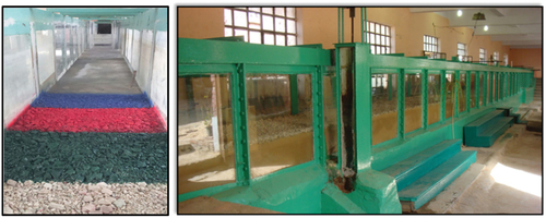
Figure 3. Longitudinal view of the physical model of the new regulator in the flume.
Figure 4. Plan view of the physical model of the new regulator in the flume.
where Fr is the Froude number, v is the average flow velocity (m/s), h is the characteristic depth, (m) and g is the gravitational acceleration (m/s2). From the condition that the Froude Number in both prototype and model should be equal, the scale ratios for velocity, discharge, time, forces, and others can be determined:
Length Scale = nL = 8.5
Velocity scale ratio = nv = (nL)0.5 = 2.92
Discharge scale ratio = nQ = (nL)2.5 = 210.64
Time scale ratio = nt = (nL)0.5 = 2.92
The model simulates a length of 92 m upstream the regulator and 78 m at downstream side including the one vent of Bahr Yousef regulator. The modeled structure consists of one vent of the regulator and two half piers of 1.25 m wide each (prototype scale) manufactured from Plexiglas. The upstream water level controlled by two gates made of Plexiglas each gate with 3.3 m height. In the first test phase, the gates used as a weir. In phase 2, the flow passes under the gate. The Stilling basin consists of two parts; Sill under gate followed by a horizontal apron. The geometry and the dimension used for constructing the proposed design in the model is shown in as a plan view while shows longitudinal section. These measuring devices are the electromagnetic flowmeter for measuring the flow discharge, the electromagnetic current meter for measuring the flow velocity and the point gauge for adjusting the water level at both the upstream and downstream the gate. The scour hole downstream the apron was measured by using point gauge.
Figure 5. Plan section of Bahr Yousef new regulator.
Figure 6. Longitudinal section of the proposed design new Bahr Yousef regulator.
Model test program
There were two phases of investigations: phase one (flow over the gate), phase two (flow under gate). Both phase one and phase two have four cases. Forty-eight experimental tests were carried out.
In phase one the gate acting as a weir and the river flow discharges ranging from 18.52 m3/s to 227 m3/s. The flow discharge over weir was checked by using the equation of the sharp crested weir eq. (2) in order to identify the head over weir and calculate the discharge.
where Q is the discharge, Cd is the discharge coefficient, B is the width of the vent, g is the gravity acceleration, and H is the height of the flow above the gate.
In phase two, the passing under gate consequently the gate was calibrated to define the different gate openings for different flow conditions, the river flow discharges ranging from 18.52 to 227 m3/s. The gate openings were increased from 0.15 m with low discharge corresponding to 18.52 m3/s until it reaches 3.02 m with discharge 227 m3/s (high discharge) (Case 1 and 2) and from 0.15 m with low discharge corresponding to 18.52 m3/s until it reaches 3.78 m with discharge 227 m3/s. The flow discharge under the gate is calculated by using eq. (3).
where Q is the discharge, Cd is the discharge coefficient equal 0.61, B is the width of the vent, a is the gate opening, g is the gravity acceleration, and H is the head difference.
Each phase consists of four cases (Case 1, Case 2, Case 3, and Case 4) and with each case the velocity were measured at six profiles namely A, B, C, D, E, and F. The locations of the Profiles from A to F as shown in are at distance of 11.72 m; 20.48 m; 28.98 m; 43 m; 58.05 m; and 73.09 m downstream the gate respectively. For case (1) The Rip-Rap protection covered distance 71.4 m upstream stilling basin and covered distance 41.74 m from the end of 30 m concrete blocks area downstream new regulator. For case (2&3) Riprap protection covered distance 71.4 m upstream stilling and covered distance 71.74 m from the end of basin area (Apron) downstream new regulator. The D50 of the Riprap that covered the downstream area is 40 cm. For case (4) the D50 of the Riprap that covered the downstream area is 20 cm. shows the results of each test made for all the cases showing the prototype and the model discharge, the measured upstream, downstream levels, D50 of the downstream riprap layer, number of operational gates, the gate heights and openings.
Figure 7. Locations of the velocity profiles.
Table 1. Test Program for Cases 1, 2, 3, and 4.
The upstream water maintained constant with all flow discharges and set as 46.30 m+msl and the downstream water value calculated from tail water rating curves (ranging from 42.55 m+msl to 45.82 m+msl).
For two cases (1 and 2), the discharge is passing through four gates and the discharge per gate is calculated using eq. (4). For two cases (3 and 4), the discharge is passing through three gates and the discharge per gate is calculated using eq. (5).
where Qm is the model discharge for one vent, Qt is the total discharge, and (nh)2.5 is the discharge scale ratio.
Results and discussion
The experimental results were analyzed and discussed in order to evaluate the performance of different stilling’s design. The results were presented as a comparison between the two phases (Flow over Gate & Flow under Gate). The comparison included the characteristics of the velocity distribution, the pressure head, the energy dissipation, the stability of bed protection downstream the concrete slab. and the characteristics of the submerged hydraulics jump were discussed.
Velocity Distribution
The flow velocity distribution for the dominant discharge for Case 1, Case 2, Case 3, and Case 4 is showed in , and respectively, also the figures show the velocity distribution for the tested discharges by using (surfer) which clarify the position of the zero point of velocity and the distance at which the flow started to be normal. The zero point was found between forward and backward flow at the same profile. The velocity distribution of cases 3 and 4 is found to be the same and showed in .
Figure 8. Comparison of velocity distribution between Flow over and under Gate at dominant discharge, Case 1.
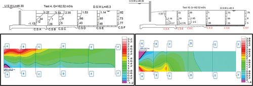
Figure 9. Comparison of velocity distribution between Flow over and under Gate at dominant discharge, Case 2.
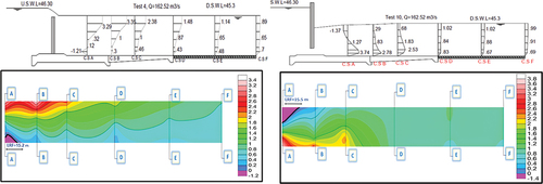
Figure 10. Comparison of velocity distribution between Flow over and under Gate at dominant discharge Case 3 and 4.
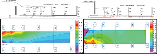
In case of flow over gate, in low discharges due to big difference between upstream and downstream levels, the velocity distributions close to the gate were forward flow near to bed and backward flow in the surface except Test-1 (minimum discharge the velocity distribution was backward flow near bed apron and forward flow near surface at (Cross section A) because the nap of the jet couldn’t penetrate the flow and follow the same direction of the flow. In dominant and high discharges (Test 4, Test 5, and Test 6) due to the low head difference between upstream and downstream the velocity distributions close to the gate is backward flow near to bed and forward flow close to surface due to the fluctuation that resulted from turbulence flow. The maximum velocity near to bed was 2.99 m/s for (Case 1 and 2) and 4.33 m/s for (case 3 and 4) at at test-3 corresponding to discharge 120 m3/s at C.S (A) directly downstream the gate. The max near bed velocity reaches 0.83 m/s (Case 1), 0.69 m/s (Case 2), and 0.92 m/s (Case 3) at C.S (D). The maximum near bed velocity at C.S (F) at the end of blocks area was at Test-6 corresponding to discharge 227 m3/s and it was 0.98 m/s (Case 1), 0.9 m/s (Case 2), and 1.1 m/s (Case 3).
In case of flow under gate, the velocity distribution near to gate is forward flow near to bed and backward flow close to the surface due to the jet of under gate flow, except test-7 (minimum discharge the velocity distribution was backward flow near bed apron and forward flow near surface at (Cross section A) because the jump occurred almost under the sill of the gate. The max near bed velocity reaches 3.25 m/s for (Case 1 and 2) and 4.27 m/s for (Case 3 and 4) at Test-9 corresponding to discharge 120 m3/s at C.S (A) directly downstream the gate. The near bed velocity reaches 1.1 m/s (Case 1 and 2) and 1.18 m/s (Case 3 and 4) at Test-12 with discharge 227 m3/s at C.S(D). The maximum velocity at C.S (F) at the end of protection area was at Test-12 corresponding to discharge 227 m3/s and it was 0.95 m/s (Case 1), 0.82 m/s (Case 2), and 1.1 m/s (Case 3 and 4).
Pressure distribution
The pressure head is measured at different locations starting at the end of sill under gate and ending at 3.4 m (proto.) upstream the end of apron. The location of the pressure measurements is showed in . The pressure distribution of flow over gate and flow under gate are showed in .
Figure 11. Locations of Pressure Cells.
The Rip-Rap protection covered distance 71.4 m upstream stilling basin and covered distance 41.74 m from the end of 30 m concrete blocks area downstream new regulator.
Water Surface Profile
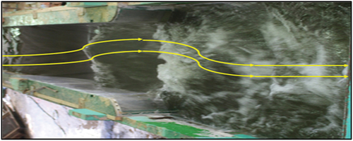
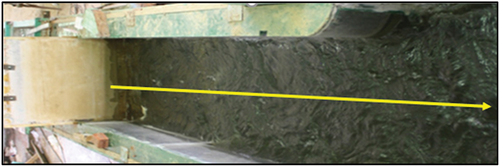
In case of flow over gate, has a drawn lines indicates the stream lines showing that the minimum pressure head was at the sill under gate (cell-1) for all tests. The value of pressure head in Cell-2 in the first three tests in bigger than other cells because of the jet occur due to the big difference between levels of upstream and downstream, see . This difference in Cell-2 does not exist in rest tests because there was no jet downstream the gate because the difference in levels of upstream and downstream is small, see . In case of Flow under Gate, the minimum pressure head was at the sill under gate (cell-1), for all cases.
Figure 12. Pressure distribution over gate (left) and under gate (right).
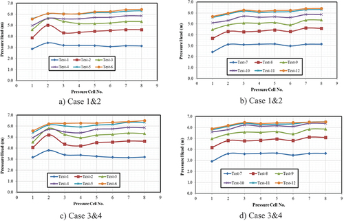
Figure 13. Flow Downstream Gate, Test2.
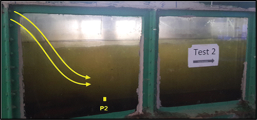
Figure 14. Flow Downstream Gate, Test 4.
In case of flow over gate, the water surface profile was high turbulent that caused fluctuation in the flow indicated by the yellow lines in .
Figure 15. Water surface profile, Flow over Gate.
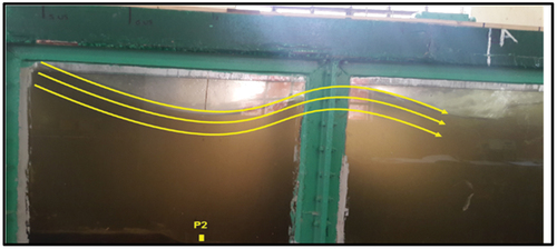
In case of flow under gate, the water surface was normal due to the normal velocity distribution indicated by the yellow lines in .
Figure 16. Water surface profile, Flow under Gate.
Characteristics of flow
Characteristics of flow over gate were presented as follows; when the gate rested on sill under gate, we didn’t control the upstream water level, so it reached 46.33 m+msl in Test-5 and 46.59 m+msl in Test-6 in Case 1 and 2 and 46.85+msl in Test-6 in Case 3 and 4. The flow was submerged flow because the gate crest level was bigger than downstream level for all cases. The discharge coefficient Cd was ranged from 0.46 to 0.74 in Case 1 and 2 and ranged from 0.38 to 0.75 as in Case 3 and 4.
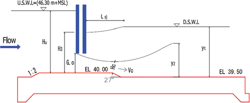
Characteristics of Flow under Gate were investigated in order to define the discharge coefficient Cd also, the hydraulic jump the characteristics of the hydraulic jump were investigated in order to classify its type. The conditions that applied for all tests and the measured and calculated parameters are shown in .
Figure 17. Parameters of the Hydraulic Jump Characteristics.
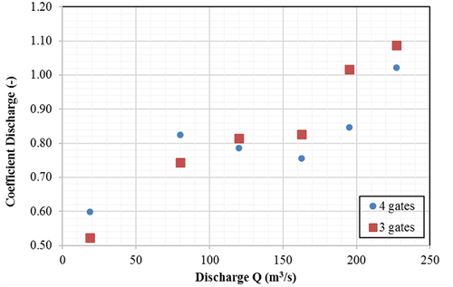
The discharge coefficient Cd was ranged from 0.6 as minimum value corresponding to Test-7 to 1.02 as maximum value corresponding to Test-12 in Case 1 and 2 and ranged from 0.52 as minimum value corresponding to Test-7 to 1.15 as maximum value corresponding to Test-12 in Case 3 and 4 as shown in . The maximum Froude No. was found 5.37 at Test-8 corresponding to discharge 80 m3/s, also the Froud. No > 1 for Test-11, Test-12 (Case 1 and 2), and for Test-11, Test-12 (Case 3 and 4). This means that the flow was subcritical flow and there wasn’t a hydraulic jump occurred.
Figure 18. Relation between discharge and discharge coefficient (Flow under gate).
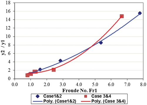
The direct proportional relationship that was between Froude No and Sequent Water Depth for all cases is showed in . The maximum and minimum Sequent Water Depth (Y2/Y1) were presented by Tests-7 and -10 respectively, as Test-7 has minimum discharge and Test-10 has maximum discharge.
Figure 19. Relation between the sequent water depth (Y2/Y1) and the Froude No.
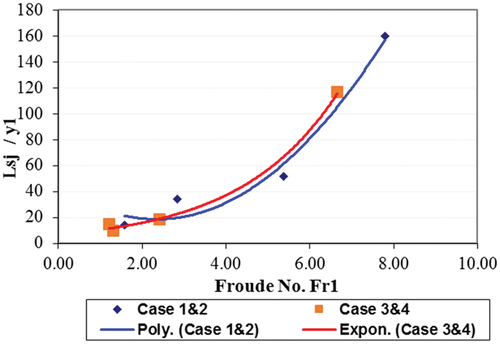
The direct proportional relationship was between Froude No and Relative Length of Jump (Lsj/Y1) is showed in . The maximum and minimum of Relative Length of Jump (Lsj/Y1) were presented by Test-7 and Test-10 respectively, as Test-7 has minimum discharge.
Figure 20. Relation between the relative length of submerged jump Lsj/y1 and Fraud No.
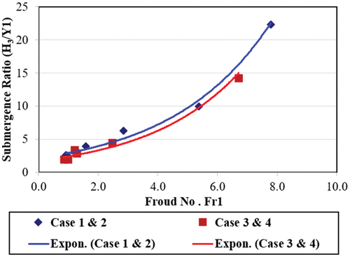
The direct proportional relationship that was between of Submergence Ratio (H3/Y1) and the Froude No. Fr for the four cases is showed in . The maximum and minimum of Submergence Ratio (H3/Y1) were presented by Test-7 and Test-10 respectively, as Test-7 has minimum discharge and Test-10 has maximum discharge.
Figure 21. Relation between the Submerged ratio (H3/Y1) and the Froude No.
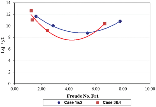
The inverse proportional relationship that was noticed between Froude No and the Jump (Lsj/Y2) as showed in . The maximum of the Jump length (Lsj/Y2) was presented by Test-10, as Test -10 has maximum discharge.
Figure 22. Relation between the jump length Lsj/y2 and Froud No.
Energy Losses
In case of Flow over Gate it was difficult to calculate the energy at Sec A because of the turbulent flow so, the energy losses were calculated between Sec B & Sec D (where the velocity started to be normal) by using eq. (6):
where h is the pressure head, v is the mean velocity
The Energy losses were calculated based on the measured pressure head (h) at the cell in horizontal apron (h1) located at Sec B (where the velocity started to be normal), and the cell (h2) at 3.4 m upstream the end of apron as showed in and based on the average velocity ((v0.2+v0.8)/2, v0.6) at Section B and the average velocity ((v0.2+v0.8)/2, v0.6) at Section D at the end of the apron.
In case of Flow under Gate the energy losses calculated at the distance of the hydraulic jump (from sec1 to sec 2), see . The Energy losses at section 1 (at vena contracta) was calculated by using eq. (7) (Rajaratnam, Citation1965):,
where E1 was the energy at Section 1(at vena contracta), H3 was the backup water depth (water depth just downstream the vertical gate), Hc was the height of the jet at vena contracta, Fr1 was the Froude No. (at vena contracta).
Also, the total energy losses between Section 1 and Section 2 were calculated by using eq. (8) (Rajaratnam, Citation1965):,
where, St was the submergence, Yt was the tail water depth.
In addition, the relative energy losses EL/E1 *100 was also calculated in order to check the efficiency of the design of new regulator stilling basin. shows that the comparison of energy losses EL/E1 for (Flow over Gate &Flow under Gate).
Table 2. Energy losses, flow over gate &flow under gate.
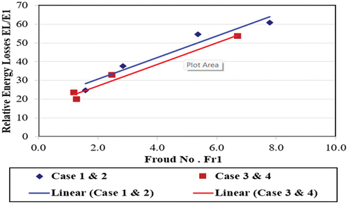
shows that the ratio of the energy losses ranged between 1.08 % to 8.06 % (Case 1 and Case 2) and ranged between 1.36% to 9.83 (Case 3 & Case 4) for flow over gate. These low ratios indicated that the whole of the energy was lost directly downstream the gate (that explained the fluctuation happened) and this was bad dissipation. also showed that the ratio of the energy losses was ranged between 43.9% to 24.45% (Case 1 and Case 2) and ranged between 19.7% to 33.7 (Case 3 & Case 4) for flow over gate. The dissipation of the energy was normal. A direct proportional relationship was noticed between Froude No and Relative Energy Losses (EL/E1) is shown in . The maximum and minimum of Relative Energy Losses (EL/E1) were presented by tests-7 and -12 respectively, as test-7 has minimum discharge and test-12 has maximum discharge.
Figure 23. Relation between Froude No. and Relative Energy Losses.
Stability of Rip-Rap Protection
The stability of rip-rap protection layer was investigated for different flow discharges ranging from 18.52 to 227 m3/s.
The criteria for selection of the Rip-Rap size include a stability coefficient B׳. The stability coefficient B’ indicates that the riprap is stable if B’ below 1.25. Remembering that the stability of the Rip-Rap downstream of a stilling basin depends on both velocity and turbulence level, the stability coefficient was formulated by Römisch, et al Citation1995.
where B’ was the stability coefficient, Vbottom was the bottom velocity, SDV was the standard deviation of the velocity fluctuations, d50 was the mean size of Rip-Rap particles, and Δ’ was the relative density of the submerged Rip-Rap.
The regulator bed protection (riprap) was found safe at (sec F) for all tested flow conditions of Case one, so we replaced the concrete blocks by riprap with d50 = 40 cm in Case 2. The maximum stability coefficient (B’) was found 0.766 at C.S(F) for high discharge 227 m3/s. The regulator bed protection (riprap) was found safe for all tested flow conditions of Case two. The maximum stability coefficient (B’) was found 0. 620 at (C.S.D) for high discharge 227 m3/s. regulator bed protection (riprap) was found stable for all tested flow conditions of Case 3, so we minimize the Size of riprap to d50 = 20 cm in Case 4. The maximum stability coefficient (B’) was found 0.784 at C.S(D) for high discharge 227 m3/s. The regulator bed protection (riprap) was found stable for all tested flow conditions of Case 4. The maximum stability coefficient (B’) was found 1.08 at C.S(D) for high discharge 227 m3/s.
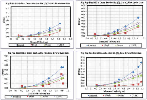
There were different equations to calculate the size of d50 that used in the protection layer (Peterka, Citation1958), Khairy Saleh (Citation1995), (Khairy Saleh, Citation1995), and Isbash (Citation1936) (Isbash, Citation1936). Romisch equation gave the largest size of riprap so we applied Romisch Equation to check the stability of protection layer.
The measured velocity at cross section D in Case 2 (flow over gate) was ranged from 0.1 to 0.83 m/s and d50 ranged from 3 to 7 cm at velocity 0.83 m/s, the measured velocity at cross section D in Case 3 (flow over gate) was ranged from 0.2 to 0.92 m/s and d50 ranged from 3 to 10 cm at velocity 0.92 m/s, the measured velocity at cross section D in Case 2 (flow under gate) was ranged from 0.16 to 1.1 m/s and d50 ranged from 2 to 11 cm at velocity 1.1 m/s and the measured velocity at cross section D in Case 3 (flow under gate) was ranged from 0.25 to 1.18 m/s and d50 ranged from 4 to 17 cm at velocity 1.18 m/s, see .
Figure 24. Relationship between velocity and Mean grain Diameter.
Conclusion
In case of flow over gate
In low discharges, the velocity distributions close to the gate was has two main parts forward flow near to bed and backward flow in the surface. While in the dominant and high discharges (test 4, test 5, and test 6) the velocity distributions close to the gate was backward flow near to bed and forward flow close to surface due to the fluctuation that resulted from turbulence flow.
The minimum pressure head was found at the sill under gate (cell-1) for all tests in four Cases. Generally the water surface profile downstream the gate in case of the flow over gate was high turbulent that caused fluctuation in the flow.
The ratio of the energy losses was ranged between 1.08% and 8.06% (Case 1 and Case 2) and ranged between 1.36% and 9.83% (Case 3 and Case 4), these low ratios indicated that the whole of the energy was dissipated directly downstream the gate.
D50 of the rip rap ranged from 3 to 10 cm with the maximum discharge (case 3 and 4). The safe size of rip rap in case of flow over gate was smaller than that in case of flow under gate, however the ratios of energy loss in case of flow over gate was less than that in case of flow under gate.
In case of flow under gate
The velocity distribution downstream the gate has two components, one component is forward flow near to bed and the second one is backward flow close to the surface. With the minimum discharge the velocity distribution has a backward flow near bed and forward flow near surface.
The minimum pressure head was found to be at the sill under gate (cell-1) for all tests in four cases. The water surface condition is better than the flow over gate with smooth surface.
The discharge coefficient Cd was ranged from 0.6 to .87 in Case 1 and 2 and ranged from 0.52 to 0.83 in Case 3 and 4. As the value of Cd approach to 1 as the actual discharge approach to the theoretical discharge this indicated the discharge flow with high efficiency.
The ratio of the energy losses was ranged between 43.9% and 24.45% (Case 1 & Case 2) and ranged between 19.7% and 33.7% (Case 3 & Case 4).
D50 of the rip rap protection is ranged from 4 to 17 cm at the maximum discharge (case 3 and 4).
According to the obtained results
The best operation of the gate was found with Flow under gate which has normal velocity distribution, water surface without fluctuation and turbulence, with high dissipation energy and the high value of Cd. The best design was (The design of Case 4) as it was safe design in case of operation four gates or three gates (one closed vent); moreover, it was more economic when we replace 30 m of concrete blocks by riprap layer with d50 = 20 cm as it minimized the cost of the protection layer by 80%.
Recommendation
Based on the results of the study the following main points are recommended for future investigation:
Try to less the length of the Apron to make the design more economic as the values of velocities were not high.
Acknowledgments
This research is a part of Master thesis of the last author under supervision of the other authors. All authors are appreciatively acknowledging the Hydraulics Research Institute (HRI), National Water Research Center (NWRC), Ministry of Water Resources and Irrigation (MWRI), Egypt for collaboration and facilitating the physical modeling.
Disclosure statement
This research was conducted independently, and no conflicts of interest or external funding were involved in this investigation. The findings presented herein are based on rigorous experimentation and analysis, adhering to established scientific methodologies.
References
- Demirel, E. (2015). Measured and simulated flow downstream of the submerged sluice gate. Water and Environment Journal, 29(3), 446–455. https://doi.org/10.1111/wej.12119
- Gumus, V., Simsek, O., Soydan, N. G., Akoz, M. S., & Kirkgoz, M. S. (2016). Numerical modeling of submerged hydraulic jump from a sluice gate. Journal of Irrigation & Drainage Engineering, 142(1), 04015037. https://doi.org/10.1061/(ASCE)IR.1943-4774.0000948
- Habib Zadeh, A., Wu, S., Ade F, Rajaratnam, N., & Loewen, M. R. (2011). Exploratory study of submerged hydraulic jumps with blocks. Y.1943-7900.0000347 Journal of Hydraulic Engineering, 137(6), 706–710. https://doi.org/10.1061/(ASCE)HY.1943-7900.0000347
- Isbash, S. V. (1936). Construction of dams by depositing rocks in running water. In A. Dovjikov (Ed.), Proceeding of second congress on large dams (pp. 123–136). Washington D.C: International Congress on Large Dams.
- Khairy Saleh, O. (1995). River training and protection for reach downstream of hydraulic structures. Al Sharqia Egypt: Zagazig University Faculty of Engineering.
- Leutheusser, H. J., & Fan, J. J. (2001). Backward flow velocities of submerged hydraulic jumps. Journal of Hydraulic Engineering, 127(6), 514–517. https://doi.org/10.1061/(ASCE)0733-9429(2001)127:6(514)
- Ma, F., Hou, Y., & Prinos, P. (2001). Numerical calculation of submerged hydraulic jumps. Journal of Hydraulic Res, 39(5), 493–503. https://doi.org/10.1080/00221686.2001.9628274
- Mohamed, Y. A., Saleh, Y. K., & Ali, A. M. (2015). Studying The Effect of Different Configurations and Positions of Sill over Stilling Basin on Flow Characteristics Behind Radial Gate,(Case Study: Nagaa Hammadi Regulator). Journal of Engineering Sciences, 43(3): 311–329/2. https://doi.org/10.21608/jesaun.2015.115186
- Negm, A. M., Alhamid, A. A., & El-Saiad, A. A. (1995). Submerged flow below sluice gate with sill. Advances in Hydroscience and Engineering, Beijing, China, March 22-26, 1995. 1073–1082. Tsinghua University Press.
- Negm, A. M., El-Saiad, A. A. (1993). Subcritical submerged flow characteristics beneath silled sluice gates. In M. ElSadek (Ed.), Advances in Engineering and Hydroscience International ConferenceCairo, Egypt, 1993, Cairo water and water structures Engineering Department4, pp. 298–309. Naser City, Cairo, Egypt: Faculty of Engineering, Al-Azhar University.
- Peterka, A. J. (1958). Hydraulic Design of Stilling Basins and Energy Dissipator (3rd ed.). United States: United States Bureau of Reclamation. https://doi.org/10.6028/WRP25
- Rajaratnam, N. (1965). Submerged hydraulic jump”. Journal of the Hydraulic Div, 91(HY4), 71–96. https://doi.org/10.1061/JYCEAJ.0001296
- Römisch, K., Elsadek, M., Negm, A., ElSaiad, A., ElAwadi, M., ElNaggar, M., & ElSayed, M. (1995). New assuit barrage hydraulic model investigation of modified layout 3-6, Barrage model, phase 2. International Conference on Hydraulic Engineering, Cairo, Egypt, 1995. 159–179.
- Shayan, H. K., & Farhoudi, J. (2013). Effective parameters for calculating discharge coefficient of sluice gates. Flow Measurement and Instrumentation, 33, 96–105. https://doi.org/10.1016/j.flowmeasinst.2013.06.001