
 ?Mathematical formulae have been encoded as MathML and are displayed in this HTML version using MathJax in order to improve their display. Uncheck the box to turn MathJax off. This feature requires Javascript. Click on a formula to zoom.
ABSTRACT
Nonlinear weirs offer a relatively high discharge capacity under low water loads. Their efficiency, however, is decreased at high water loads due to the submergence of the weir outlet key. In the present study, sloping parapet walls with the heights of 2, 4, and 6 cm and lengths of 60 and 30 cm were added to trapezoidal labyrinth weir and piano-key weirs in order to reduce the submergence at the weir inlet. The experiments were conducted in a test flume with a length of 7 m and a width and height of 0.6 m. Results of this study suggested that addition of the sloping parapet walls could reduce discharge coefficient by at least 10% and 13% in Piano-Key Weirs and labyrinth weirs respectively as compared to the control cases. Also, after addition of the parapet walls, Piano-Key Weir outperformed labyrinth weir by up to 19% in terms of the discharge coefficient. The highest efficiency of parapet wall for Piano-Key Weirs was found to be corresponding to parapet wall length and height of 30 cm and 2 cm respectively which differed from that of labyrinth weir of the same parapet wall dimensions by 14%. In fact, the addition of the parapet walls to the labyrinth and piano-key weirs increases the efficiency at high discharges by up to 40%.
Introduction
Given the increasing demand for water storage in the recent years, the need for hydraulic structures such as dams is felt more. However, such structures may also contribute to formation of floods of larger scales in case of failure (Anderson & Tullis, Citation2013). Improving the safety of the dams calls for the construction of high-efficiency weirs (Gonzalez & Chanson, Citation1995). Labyrinth weirs are hydraulic structures used for water level regulation and flow control in dam reservoirs. The crest axis in this type of weir is nonlinear and, in the plan view, the weir crest is composed of series of connected walls that form a periodical triangular, trapezoidal, rectangular, or arced geometry ().
Figure 1. Trapezoidal labyrinth weir (plan view).
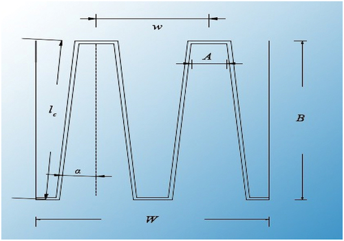
In , W is the total width of the weir, w is the width of a complete cycle, A is the inlet width of the weir, B is the weir length, lc is the side length of the weir, and α is the sidewall angle of the keys. The basic idea behind the design of labyrinth weir is to increase water transfer capacity over a fixed-crest weir for a given water level upstream of the weir (Lux & Hinchliff, Citation1985). The discharge capacity of weirs is calculated from EquationEquation (1)(1)
(1) (Abdel Aal, Sobeah, Helal, & El-Fooly, Citation2018):
In EquationEquation 1(1)
(1) , Q denotes the effective discharge, Cd is the discharge coefficient, g is gravitational acceleration, L represents the developed crest length, Ht stands for the total head (sum of velocity and hydrostatic heads) over the crest. Based on this equation, the effective discharge in a weir can be increased by extending weir width, decreasing the height of the weir crest, increasing the length L over the existing weir foundation, or replacing the existing weir with a nonlinear one (labyrinth type) (Babb, Citation1979). Increasing the length (L) of the linear weir, and consequently its discharge canal width, is not practically feasible due to the dam geometry and/or cost-related reasons. In addition, decreasing crest height lowers the operating water level of the reservoir behind the Dam, consequently decreasing the amount of stored water available (Kabiri-Samani, Citation2010). Nonlinear weirs thus offer a valuable alternative. PKWs are considered an appropriate alternative to weirs with a poor performance at maximum discharge () (Lempérière & Ouamane, Citation2003).
Figure 2. Trapezoidal piano-key weir.
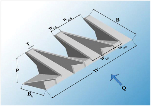
In , P denotes the height of the inlet/outlet entrance measured from the weir crest, W represents the total width of the weir, Wi stands for the inlet key width, and Wo represents the outlet key width. These weirs have nonlinear crests which enable them to pass a greater flow rate compared to the weirs with linear crests of similar width and height (Lempérière & Ouamane, Citation2003). In contrast to labyrinth weirs, the openings in PKWs have alternately inward and outward slopes. Compared to labyrinth weirs, PKWs occupy a smaller space, making it possible to use such weirs at the crest of concrete dams (Lempérière, Citation2017). Machiels, Erpicum, Archambeau, Dewals, and Pirotton (Citation2013) investigated the effect of parapet walls at a constant weir height and concluded that these walls mainly increased the total head of the weir. Javaheri and Kabiri-Samani (Citation2012) studied the effect of different geometrical parameters and proposed a relation for estimation of the discharge coefficient for free flows. Afzalian and Ahadiyan (Citation2015, Citation2016) examined the effect on PKW efficiency of sloping parapet walls along and opposite to the flow direction. They reported that sloped parapet walls elevated the upstream water level. Likewise, they studied the effect on PKW performance of different base geometries, including triangular, flat, and semicircular geometries. They observed that the triangular base achieved the highest efficiency. In this case, the results are sufficiently accurate and can be used in the preliminary design stages. Evidently, in the final design, the physical model should be fabricated based on the results of the preliminary design so that it can be accurately assessed (Lux, Citation1993). Since the construction costs are not affected by the side wall angle (α) (), this angle should be set to the largest value in the design in order to achieve the highest hydraulic efficiency. In cases where the in-plan triangular pattern is not desired for some reason, a labyrinth weir with trapezoidal geometry, in which a/w = 0.765 or α = a = 0.75max α, would be the recommended alternative (Hay & Taylor, Citation1970). In their study, Tullis et al. concluded that increasing the hydraulic head (h) increased the discharge coefficient (Cd) and that the best performance of labyrinth weirs is achieved at relatively low hydraulic heads (Tullis, Amanian, & Waldron, Citation1995). Lempérière and Ouamane (Citation2003) investigated two PKW model types A and B, where the former had an arch, whereas the latter had no arch but included a longer slope compared to the former. They reported that for a given weir height (P) and number of weir cycles (N), Type B outperformed Type A by 10 percent. Anderson and Tullis investigated different PKW geometries and concluded that the discharge coefficient of the weir increases by increasing the Wi/Wo ratio, the optimal value of which falls within the range 1.25 to 1.5 (Anderson & Tullis, Citation2013). They also stated that upstream and downstream overhangs improve the discharge efficiency, and installation of nose has a positive effect on efficiency. Guodong, Shanshan, and Yuan (Citation2020) numerically studied the flow characteristics of nine laboratory-scale PKWs with different Wi/Wo ratios. The results confirm that PKW configurations with Wi/Wo >1 generally outperform those with Wi/Wo < 1 in terms of discharge capacity. Karimi et al. investigated Rectangular Piano Key Side Weirs (RPKSW) in a straight channel. They showed that C-Type RPKSWs and rectangular labyrinth side weirs are more effective than related linear side weirs in terms of discharge capacity (Karimi, Attari, Saneie, & Jalili Ghazizadeh, Citation2018). Hu et al. conducted an exhaustive numerical study to better understand the flow patterns in PKWs. They found that at high levels of upstream hydraulic head, an increase in upstream hydraulic head of the water, the flow velocity along the inlet keys led to reduction in discharge efficiency (Hu, Qian, Yang, Hou, & Du, Citation2018). Saghari, Saneie, and Hosseini (Citation2019) examined type-A trapezoidal piano key side weirs (TPKSWs) in a curved channel. They proposed an empirical equation to calculate the discharge coefficient of a type-A TPKSW. Ghanbari and Heidarnejad (Citation2020) studied the effect on discharge coefficient of rectangular PKWs with a triangular notch. They found the discharge coefficient of triangular PKWs to be 25% larger than that of the rectangular PKWs. Their results also indicated that with suitable modifications in the notch form in the inlet keys of the weirs could be achieved discharge coefficients of 36% and 13% higher in value for weirs with the height of the inlet/outlet entrance (measured from the PKW crest) of 5 cm and 7.5 cm respectively. Kumar, Sihag, Tiwari, and Ranjan (Citation2020) studied the trapezoidal piano key weir (TPKW) and evaluated the discharge equation of these weirs. They finally developed an equation using the M5 intelligent method for determining the discharge coefficient. PKW is a nonlinear weir that has several advantages over other weir types in terms of the space occupied, discharge capacity, and upstream head of the weir (Li, Li, Jiang, & Ning, Citation2020). Aghashirmohammadi, Heidarnejad, Purmohammadi, and Masjedi (Citation2023) installed two, four or six vanes at regular intervals on the weir crest in the physical model they studied. Their results showed that the triangular weir has a 4% higher efficiency than its trapezoidal counterpart and that the vanes have stronger effects on the trapezoidal weirs. Blades can improve the overflow efficiency by up to 11%, and the discharge coefficient in the numerical simulation is 10.2% higher than the physical model.
Non-linear weirs, including labyrinth weirs and PKWs, are among the newest types of weirs that have become common in recent years and are considered as a suitable alternative to the weirs that face problems when passing the maximum possible discharge. By setting up a laboratory model, the present study attempted to compare the discharge coefficient and other hydraulic parameters in trapezoidal PKW and labyrinth weirs in the presence of a parapet wall (in order to increase the efficiency of these weirs). Based on the previous studies, the most appropriate method to study and assess labyrinth weirs is to build a physical model at a proper scale which involves placing at least one cycle of the weir in a test flume under sub-critical flow conditions.
Experiment setup
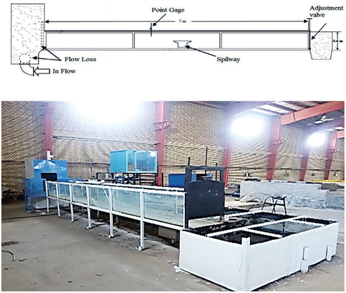
Research has shown that the most suitable method for study and evaluation of labyrinth weirs is to construct physical models of proper scale with at least one cycle and placing it inside the test flume under a subcritical flow condition. The results thus obtained will then be of sufficient accuracy to be used in the design. Obviously, for final design, it will be necessary that the physical model is constructed based on the results of the preliminary design and studied more closely (Lux, Citation1993). Following the above approach, the present study was conducted to investigate TLWs and PKWs with parapet walls. The tests were carried out at the Khuzestan Water and Power Authority laboratory and using a test flume 7 m long, 0.6 m wide and 0.6 m high ().
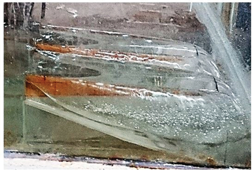
Figure 3. The test flume used to conduct the experiments.
The experiments were performed with models of TLWs and PKWs made of plexiglass. The experiments were carried out at ten different discharges so that the effect on Cd and discharge-scale curve of parapet walls as well as the effect on Cd of Fr and We numbers could be investigated. In order to achieve that purpose, control tests were initially conducted using TLWs and PKWs of non-sloping parapet walls.
In the next stage, parapet walls were added to the TLWs and PKWs and the experiments were performed at ten different discharges ranging from 0.001 m3/s to 0.05 m3/s. The experiments were carried out with six models. Shown in is the coding of the experiments conducted. Results are shown in .
Table 1. Test variables.
Table 2. Characteristics of the weir models used.
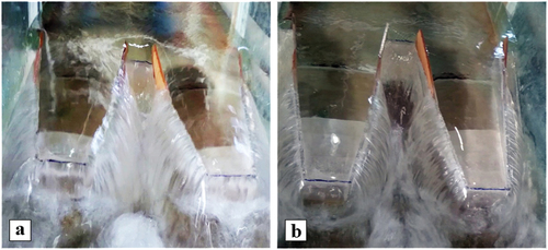
As can be seen in , in total, 140 experiments involving 14 models tested at 10 different discharges were performed to determine the effect on Cd of parapet walls in TLWs and PKWs. depicts some of the models used in the experiments.
Figure 4. The weir experimented in the test flume. a) 4P model, b) 5P model.
Experiment setup
By constructing a number of models for trapezoidal labyrinth weirs (TLW) and piano-key weirs (PKW), the present study investigated the effect of the parapet walls installed on the sidewalls of the weir on the discharge coefficient (Cd) and rating curve, as well as the effect of Froude number (Fr) on the discharge coefficient at different discharges. To this end, the control experiments were initially conducted on the labyrinth and piano-key weirs, after which the parapet walls were installed on the sidewalls of the weirs and the experiments were repeated at discharges ranging from 1 to 50 lit/s. Six different models of parapet walls (two different lengths and three different heights) were assessed in the two weir types. The details of the experiments and their coding are given in .
A schematic view of the parapet walls and their installation procedure is shown in .
Figure 5. Schematic view of the parapet walls.
Figure 6. Installation of the parapet walls.
Dimensional analysis
Parameters affecting the efficiency of weir are listed in EquationEquation (2)(2)
(2) :
where, Wi denotes the width of the inlet key, Wo stands for the width of the outlet key, Wu is the width of a single cycle (Wu = Wo +2Ts), W is the flume width, B stands for the distance from the upstream to downstream of the weir, L is the weir length, R denotes the height of the parapet wall, P is the weir height, N refers to the number of cycles, is sidewall angle, and S is the flume slope. The parameters associated with the flow and fluid properties include: H denoting the water height over the weir, μ representing the dynamic viscosity, σ standing for the surface tension (for water with a temperature of 20 °C: 0.074), ρ representing the water density (assumed to be 998.2 kg/m3), g denoting the gravitational acceleration (9.8 m/s2), Q representing the flow discharge, and V referring to the flow velocity. The following dimensionless parameters were obtained using the Buckingham’s Π technique:
In EquationEquation (3)(3)
(3) , Fr represents the Froude Number (
), Re denotes the Reynolds Number (
), We stands for the Weber Number (
), and Cd refers to the discharge coefficient
.
The minimum Reynolds number in this study is 3500, the flume slope is zero (S = 0), and the effect of Reynolds number and is neglected. Moreover, given the constant geometry of the weir, the final relationship of dimensionless parameters affecting the discharge coefficient in this research will be in the form of EquationEquation (4)
(4)
(4) :
It’s noteworthy that the Froude Numbers upstream of all of the experimented models were less than unity, hence the subcritical flow on the upstream side of the weir. According to the similitude theory, a physical phenomenon can be expressed in the functional form of the EquationEquation (5)(5)
(5) in terms of dimensionless ∏ terms:
For a specific dimensionless group of Πn, a physical phenomenon, has complete self-similarity condition if Π1 is independent of Πn. In other words, when Πn tends to zero or infinity, if the ψ function is not equal to zero or infinity therefore Πn has a complete self-similarity condition. If, however, the ψ function vanishes or tends to infinity, Πn has an incomplete self-similarity condition. In this case, the physical phenomenon is expressed as follows, EquationEquation (6)(6)
(6) :
Were ζ is the functional symbol and ɛ is a constant coefficient (Barenblatt, Citation1979; Ferro, Citation1997). By applying incomplete self-similarity theory, EquationEquation (4)(4)
(4) can be expressed as:
Where f1 is a functional symbol depending on ,
,
and We.
Results and discussion
Performance of PKW is not satisfactory at high hydraulic heads; the reason being nappe interference, turbulence, and submergence at the outlet key. Thus, the present study used parapet walls with different slopes to decrease the submergence at the weir inlet. In this section, the effect of parapet walls on the hydraulic efficiency of trapezoidal piano-key and labyrinth weirs is assessed and compared.
Effect of parapet walls on TLWs and PKWs performance
According to the results of the study conducted by Afzalian and Ahadian (Citation2016), since prior to full submergence of flow, the passing nappe is in contact with the side crest, surface tension would be of markable effect. Consequently, the variation trend of Cd with the dimensionless parameter Ht/P was surveyed separately. Effects of Ht/P are illustrated in .
Figure 7. The effect on Cd of Ht/P.
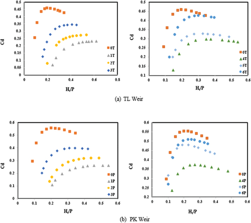
In their study, Machiels, Erpicum, Pirotton, Dewals, and Archambeau (Citation2012) reported that the parapet wall mainly increased the inlet height, which in turn reduced the longitudinal velocity caused by the increased lateral discharge. illustrates the effect on labyrinth and PKWs of addition of parapet wall. As can be seen in the figure, PKW outperformed the labyrinth weir by up to 19%. Besides, with addition of sloping side walls, Cd of PKW and labyrinth weirs was decreased by at least 10% and 13% respectively. The highest value of Cd of PKWs was found to be 0.5 and occurred in the case 6P. Similarly, the largest value of Cd of labyrinth weirs was found to be 0.43 and occurred in the case 6T. Thus, the maximum Cd of labyrinth weirs was found to be 14% smaller with respect to that of PKWs.
According to the previous studies, with increase in discharge, Cd increases initially, before it declines past a certain value of discharge. In this study, however, with increase in discharge, Cd experiences a rise until discharge reaches a specific value beyond which Cd levels off. That the discharge coefficient remains in the vicinity of its peak value can save the construction costs.
Discharge coefficient of model 3T was found to be 19% lower with respect to that of model 6T. Likewise, Cd of model 3P was found to be 20% smaller with respect to that of model 6P which reflects the improving effect of height and smaller length of the parapet wall.
Discharge vs head diagrams
In this section, the effect of parapet walls on the discharge-head curve is discussed. The graphs presented can be used to estimate the upstream water level at a given discharge. The variation of the hydraulic head with discharge in the presence of parapet walls is demonstrated in .
Figure 8. The discharge vs hydraulic head diagram.
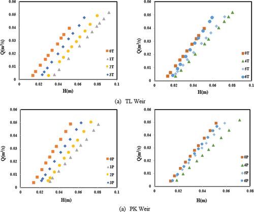
Studies of Machiels, Erpicum, Pirotton, Dewals, and Archambeau (Citation2012) suggested that lateral discharge is not directly a function of hydraulic head above the lateral crest but a function of velocity at inlet. As can be seen in , at a constant discharge, with increase in the height and length of the parapet wall, hydraulic head of the models 1T and 1P increased by 66% and 63% respectively, meaning that under the same conditions, increase in the height of parapet wall raised the hydraulic head (H).
Relationship between discharge coefficient (Cd) and Froude number (Fr)
According to the studies carried out by Machiels, Erpicum, Pirotton, Dewals, and Archambeau (Citation2012) the efficiency of PKW at low hydraulic heads along the direction of inlet key is essentially governed by the Froude Number, and it follows that the flow velocity and Froude number also affect the discharge coefficient. In order to examine the effect of flow velocity, the variations of the discharge coefficient Cd with respect to the upstream Froude number are plotted in for the studied models in presence of parapet walls.
Figure 9. Effect on Cd of Froude number (Fr).
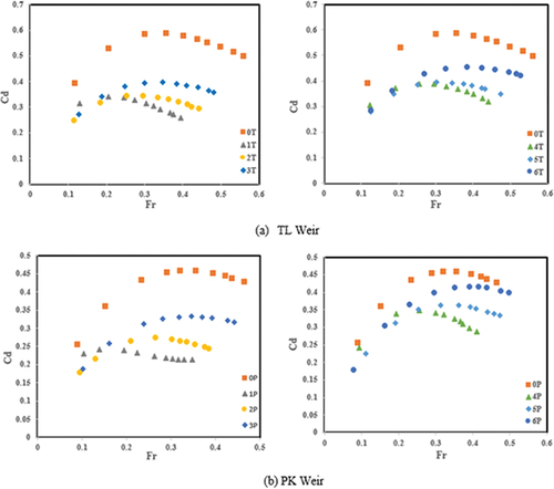
As depicted in , efficiency is improved as the flow velocity increases. As an important note, in this case, the increase in efficiency occurs at high velocities, whereas, in the previous studies, the highest efficiency occurred at low velocities, which is an indication of the positive effect of the parapet walls at high discharges, that is allowing an increased efficiency as the flow discharge increases. Hence, addition of parapet walls to both labyrinth and piano-key weirs eliminates the efficiency drop at high discharges.
With the establishment of a subcritical flow, the results become more accurate (Lux, Citation1993). Upstream Froude number of the weir was found to be less than unity in all tested models, meeting the conditions of subcritical flow on the upstream side of the weir. On the upstream of the weir, the flow is steady and calm, the flow velocity is low, and the Froude number is small.
Relationship between Cd and Weber number (We)
According to the findings of Machiels, Erpicum, Dewals, Archambeau, and Pirotton (Citation2011) obtained by comparing between flow rates measured in the scaled models and prototypes, at Weber Numbers larger than 50, the Weber Number loses its effects and flow is essentially controlled by the Froude Number. Furthermore, according to studies conducted by Afzalian and Ahadian (Citation2016) since for certain values of hydraulic head, the water on the weir is in contact with its crest, surface tension will be of marked influence. illustrates the effect on Cd of We.
Figure 10. Effect on Cd of the Weber number.
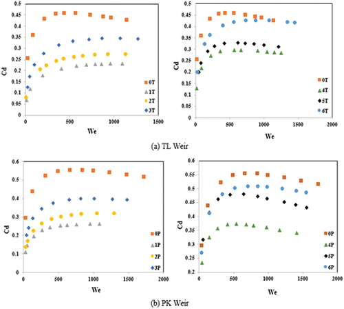
It follows from the diagrams that in both weir models, in control case, for We Numbers smaller than 100, the effect on Cd of the surface tension increased until it reached a plateau. In models with parapet wall, however, the effect on flow of surface tension increased; but this was the case up to We number of 200 beyond which surface tension stopped affecting the flow. Finally, the following equations were obtained for Cd using the statistical software SPSS:
EquationEq. 8(8)
(8) and Equation9
(9)
(9) give Cd for PKWs and TLWs respectively. As is evident from EquationEquations (8)
(8)
(8) and (Equation9
(9)
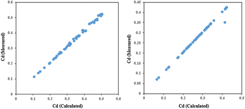
(9) ), the discharge coefficient was mostly affected by the Froude Number. Conversely, the effect on the Cd of the Weber Number was found to be minimal. Comparison between the calculated Cd and the measured Cd for TLW and PKW is shown in .
Figure 11. Comparison between the calculated Cd and the measured Cd for TLW and PKW.
Conclusion
PKWs are relatively new structures with high hydraulic performance at low hydraulic heads. In this study was surveyed the effects on PKW and TLW of addition of sloping parapet walls of two different lengths (B/B́ = 1 and B/B́ = 1/2) and three different heights (R = 2, 4, 6 cm). According to the results obtained in this study, the PKW outperformed the labyrinth weir by 19%. Also, addition of sloping sidewalls led to decrease of discharge coefficient of at least 10% and 13% in the PKW and labyrinth weirs respectively. Besides, parapet walls of smaller height and length were found to have a better effect on the discharge coefficient than had those of greater lengths.
Also, it was observed that increase in the height and length of the parapet wall led to a rise of up to 66% of the hydraulic head, indicating the fact that keeping all conditions the unchanged, increase in the height of parapet walls results in a higher hydraulic head (H). Based on the relationships obtained, the Froude number and the Weber number have the strongest and smallest effects on the discharge coefficient respectively.
Authors’ contributions
Marzieh Hamidinia participated in the study design, data collection and evaluation, and conducted the experiments. Mohammad Heidarnejad participated in the study design, data collection and evaluation, conduction of the experiments and analyses, and in charge of the overall supervision. Mohammad Hossein pourmohammadi and Alireza Masjedi contributed to all experimental work. All authors performed editing and approving the final version of this paper for submission, also participated in the finalization of the manuscript and approved the final draft.
Availability of data and material
The data that support the findings of this study are obtainable from the corresponding author.
Table
Acknowledgments
The authors would like to thank the Water and Power Authority of Khuzestan, Iran for their support in providing the required laboratory equipment.
Disclosure statement
The authors declare that they have no conflict of interest.
Correction Statement
This article has been corrected with minor changes. These changes do not impact the academic content of the article.
Additional information
Funding
References
- Abdel Aal, G., Sobeah, M., Helal, E., & El-Fooly, M. (2018). Improving energy dissipation on stepped weirs using breakers. Ain Shams Engineering Journal, 5(4), 1033–1042. doi:10.1016/j.asej.2017.01.008
- Afzalian, A., & Ahadian, J. (2016). Piano key weirs with positive parapet wall. Water Soil Science, 25(4/2), 97–107. [In Persian].
- Afzalian, A., & Ahadiyan, J. (2015). Piano key weir with sloped parapet wall. Irrigation Science Engineering, 38(2), 91–102. [In Presian].
- Aghashirmohammadi, G., Heidarnejad, M., Purmohammadi, M., & Masjedi, A. (2023). Experimental and numerical study the effect of flow splitters on trapezoidal and triangular labyrinth weirs. Water Science, 37(1), 28–39. doi:10.1080/23570008.2023.2210391
- Anderson, R., & Tullis, B. P. (2013). Piano key weir hydraulics and labyrinth weir Comparison. Journal of Irrigation & Drainage Engineering, 139(3), 246–253. doi:10.1061/(ASCE)IR.1943-4774.0000530
- Babb, A. (1979). Hydraulic model study of the Boardman reservoir weir. Pullman, Wash: R.L Al book Hydraulic Laboratory, Washington State University.
- Barenblatt, G. (1979). Similarity, self-similarity and intermediate asymptotics, consultants bureau. New York. doi:10.1007/978-1-4615-8570-1
- Ferro, V. (1997). Applying hypothesis of self-similarity for flow-resistance law of small-diameter plastic pipes. Journal of Irrigation & Drainage Engineering, 123(3), 175–179. doi:10.1061/(ASCE)0733-9437(1997)123:3(175)
- Ghanbari, R., & Heidarnejad, M. (2020). Experimental and numerical analysis of flow hydraulics in triangular and rectangular piano key weirs. Water Science, 34(1), 32–38. doi:10.1080/11104929.2020.1724649
- Gonzalez, C. A., & Chanson, H. (1995). Hydraulic design of stepped cascades, channels, weirs and weirs. Dam Engineering, 17(4), 223–244.
- Guodong, L., Shanshan, L., & Yuan, H. (2020). The effect of the inlet/outlet width ratio on the discharge of piano key weirs. Journal of Hydraulic Research, 58(4), 594–604. doi:10.1080/00221686.2019.1647884
- Hay, N., & Taylor, G. (1970). Performance and design of labyrinth weirs. Journal of the Hydraulics Division, 96(2), 2337–2357. doi:10.1061/JYCEAJ.0002766
- Hu, H., Qian, Z., Yang, W., Hou, D., & Du, L. (2018). Numerical study of characteristics and discharge capacity of piano key weirs. Flow Measurement and Instrumentation, 62, 27–32. doi:10.1016/j.flowmeasinst.2018.05.004
- Javaheri, A., & Kabiri-Samani, A. R. 2012. Determination of discharge coefficient of PKWs in free flow state. Proc. In: Proceedings of 1th Conf & 3th Nat Conf Dams Water Power Plants. Tehran, Iran. [In Persian].
- Kabiri-Samani, A. (2010). Analytical approach for flow over an oblique weir. Transaction A: Civil Engineering, 17(2), 107–117. [In Persian].
- Karimi, M., Attari, J., Saneie, M., & Jalili Ghazizadeh, M. R. (2018). Side weir flow characteristics: Comparison of piano key, labyrinth, and linear types. Journal of Hydraulic Engineering, 144(12), 04018075. doi:10.1061/(ASCE)HY.1943-7900.0001539
- Kumar, M., Sihag, P., Tiwari, N., & Ranjan, S. (2020). Experimental study and modelling discharge coefficient of trapezoidal and rectangular piano key weirs. Applied Water Science, 10(1), 1–9. doi:10.1007/s13201-019-1104-8
- Lempérière, F. (2017). Dams and floods. Engineering, 3(1), 144–149. doi:10.1016/J.ENG.2017.01.018
- Lempérière, F., & Ouamane, A. (2003). The piano keys weir: A new cost-effective solution for weirs. International Journal on Hydropower and Dams, 5, 144–149.
- Li, S., Li, G., Jiang, D., & Ning, J. (2020). Influence of auxiliary geometric parameters on discharge capacity of piano key weirs. Flow Measurement and Instrumentation, 72, 101719. doi:10.1016/j.flowmeasinst.2020.101719
- Lux, F. (1993). Design methodologies for labyrinth weirs. Proceeding of Water Power and Dam Construction, III, 1379–1407.
- Lux, F., & Hinchliff, D. L., 1985. Design and construction of labyrinth weirs. In: Proceedings of 15th Congress of ICOLD, Lausanne Switzerland, pp. 249–274.
- Machiels, O., Erpicum, S., Archambeau, P., Dewals, B., & Pirotton, M. (2013). Parapet wall effect on piano key weir efficiency. Journal of Irrigation & Drainage Engineering, 139(6), 506–511. doi:10.1061/(ASCE)IR.1943-4774.0000566
- Machiels, O., Erpicum, S., Dewals, B., Archambeau, P., & Pirotton, M. (2011). Experimental observation of flow characteristics over a piano key weir. Journal of Hydraulic Research, 49(3), 359–366. doi:10.1080/00221686.2011.567761
- Machiels, O., Erpicum, S., Pirotton, M., Dewals, B., & Archambeau, P. (2012). Experimental analysis of PKW hydraulic performance and geometric parameters optimum. In: Proceedings of International Workshop on Piano Key Weir for In-stream Storage and Dam Safety-PKWISD, pp. 97–114.
- Saghari, A., Saneie, M., & Hosseini, K. (2019). Experimental study of one-and two-cycle trapezoidal piano-key side weirs in a curved channel. Water Supply, 19(6), 1597–1603. doi:10.2166/ws.2019.029
- Tullis, J. P., Amanian, N., & Waldron, D. (1995). Design of labyrinth Spillways. Journal of Hydraulic Engineering, 121(3), 247. doi:10.1061/(ASCE)0733-9429(1995)121:3(247)