Abstract
Oil retention in a microchannel type condenser was measured and its effect on heat transfer rate performance and pressure drop were analyzed for refrigerants R410A and R134a condensation. The heat exchanger was a 2-pass aluminum louvered-fin type consists of multiports rectangular channels with hydraulic diameter of 0.06 inch (1.7 × 10⁻³ m). The refrigerants and Polyolester oil mixtures were studied at saturation temperature from 85 to 130°F (29 to 54°C) and oil mass fraction (OMF) was varied from 0 to 6 wt.%. Oil retained in the condenser was found to be strongly dependent on the OMF and it was measured up to 11% of its internal volume. The oil retained for high mass fluxes were higher than those for low mass fluxes. The effect of mass flux on the oil retention was small for low OMFs but became more evident for OMFs of 3 wt.% and higher. The oil penalized the heat transfer capacity by as much as 10% when the OMF was 3 wt.%. For medium temperature of 105°F (41°C) the heat transfer capacities were fairly constant. Nevertheless, the high refrigerant-oil mixture viscosity of the liquid phase increased the pressure losses up to 19% compared to that in oil free conditions.
Introduction
The compressor in an air-conditioning (AC) system needs oil to prevent surface-to-surface contact, to remove heat, to provide sealing, to keep out contaminants, to prevent corrosion, and to dispose of debris created by wear (Vaughn Citation1971). A small portion of the oil circulates with the refrigerant flow through the vapor compression cycle components, while most of the oil stays in the compressor. Oil that is missing from the compressor can be held up inside the heat exchangers during actual system operating conditions. Oil retention (OR) is a complex function of fluid properties as well as geometry and configuration aspects. The circulating oil, which is missing from the compressor, can form a fairly homogeneous mixture with the liquid refrigerant or it can exist as a separate oil film inside the tubes and headers of the heat exchangers and the amount of oil retained in the heat exchangers is affected by the system operating conditions. It was observed that large amounts of OR cause a significant decrease in heat transfer rate and an increase of pressure drop (Cremaschi et al. Citation2005). In addition, if excessive lubricant is held up in the system components then improper lubrication inside the compressors can often lead to compressors mechanical failure. As a result, proper oil management is essential in order to guarantee compressor reliability, to increase the overall efficiency of the system, and to minimize the system cost by avoiding redundancy with the installation of additional oil separators and oil pumps.
Abundant literature can be found on oil and refrigerant mixtures in AC systems and comprehensive reviews can be found in Wang et al. (Citation2012), Youbi-Idrissi and Bonjour (Citation2008), and Shen and Groll (Citation2005a, Citation2005b). An early study by Sundaresan and Radermacher (Citation1996) reported on oil return characteristics in residential heat pump systems using R22, R407C, and R410A with mineral oil (MO) and synthetic polyolester (POE) oils. From their experiments, they recommended the use of POE oils with new refrigerant blends such as R407C and R410A. Biancardi et al. (Citation1996) conducted experimental and analytical efforts to determine the lubricant circulation characteristics of R134a+POE and R134a+MO pairs in a residential heat pump system and compared the behavior with a R22+MO mixture. The minimum flow rate for “the worst-case” scenario, in which the critical velocities occurred in the vertical vapor suction line, were determined by visual observations. They reported that minimum flow velocities ranging from 354 to 374 fpm (1.8 to 1.9 m/s) were required in the vertical upward suction lines when the system operated in the cooling mode. The oil return characteristic in vertical upward flows was also experimentally and theoretically investigated by Mehendale and Radermacher (Citation2000) whereof the critical mass flow rates for preventing oil film reversal in a vertical pipe were estimated. Despite the efforts in improving oil circulation characteristics, some of the oil is unable to return to the compressor and retained in the components of AC and refrigeration system, especially the heat exchangers. It is helpful to account for the amount of OR in order to gather a better understanding of its effects on heat transfer rate performance and on the pressure drop penalization for heat exchangers.
In order to determine the OR volume Shedd and Newell (Citation1998) proposed a non-intrusive, automated, optical film thickness measurement technique to be used with a wide range of fluids and flow configurations. Later, Bai and Newell (Citation2002), Shedd and Newell (Citation2004), and Schubring et al. (Citation2009) used a similar approach to describe the characteristics of annular two-phase viscous flow of air and water or air and 300 SUS alkybenzene oil. Extensive experimental flow visualization in horizontal and vertical pipes was required, and the oil film thicknesses were correlated with the oil mass flow rates, vapor velocity, and pipe diameter. Shear stress correlations were developed and verified with the experimental data. Unfortunately, this technique requires optical access to the refrigerant flow and it might not be feasible for the small tubes in microchannel heat exchangers.
The flow regime during refrigerant condensation in the actual AC applications of the microchannel heat exchanger is mostly annular and the oil film thickness is generally not uniform along the heat exchanger refrigerant path. OR is affected by the flow pattern of the refrigerant–oil mixture because the magnitude of the forces exerted on the fluid element depends on the type of motion of the fluid, relative interfacial surface area between the two phases, and velocity slip ratio between gas and liquid phases. Few researchers investigated flow patterns for refrigerant–oil mixtures used in AC systems while many researchers studied the flow characteristics for immiscible mixtures of air/water or air/pure oil. Riedle et al. (Citation1972) were among the first researchers to characterize systematically the flow of oil–refrigerant mixtures. Their analytical model, based on minimum gas velocities, introduced the concepts of void fraction, oil entrainment, and liquid film thickness for oil–refrigerant mixtures. Recently, an extensive review of flow boiling characteristics and flow patterns of refrigerant–oil mixture was presented in Bandarra Filho et al. (Citation2009).
While studies of oil return and oil transport in suction liners are quite numerous in the literature, for example Lee et al. (Citation2001) and Radermacher et al. (Citation2006), measurements of OR in condensers for AC and refrigeration systems are rather sporadic in the open literature (Youbi-Idrissi and Bonjour Citation2008). Reviews of published researches in oil effect during condensation were presented in Gidwani et al. (Citation1998) and more recently in Shen and Groll (Citation2005a). Early published works by Schlager et al. (Citation1990) reported experiments of R22 in combination with 150 to 300 SUS MO with the objective of determining the effects of oil in smooth and micro-fin tubes during evaporation and condensation of refrigerant–oil mixtures. They showed that the parameters that affect the OR during condensation were oil mass fraction (OMF), viscosity, condenser inlet and exit conditions, and saturation pressure. They observed that the decrease of heat transfer coefficient due to oil flow in the condenser was not strongly dependent on the refrigerant mass flux. Similar results were observed in the present work but only for one specific saturation temperature. At high and low saturation temperature the mass flux had a measurable effect on the heat transfer coefficient of the refrigerant and oil mixture in microchannel heat exchangers, as it will be discussed later in this article. More recent works on OR measurement in fin-and-tube evaporators and condensers of AC and refrigeration systems were published by Cremaschi et al. (Citation2005) and modeling efforts were discussed in Radermacher et al. (Citation2006). The refrigerants adopted in their works were R22, R410A, and R134a in combination with three different types of oils: MO, POE, and polyalkylene glycole synthetic lubricants. The effects of different refrigerant mass fluxes, solubility, and miscibility of the carrier fluid were experimentally investigated. OR was found to be proportional to the oil mass flow rate fraction (OMF) of the refrigerant–oil mixture in heat exchanger, which is often referred as to oil circulation ratio. OR was also observed to be proportional to the ratio of liquid film over refrigerant vapor viscosity. At constant refrigerant mass flux and OMF, an increase in oil film viscosity resulted on increased OR volume. The authors reported that for R410A+POE case an increased OMF from 1 to 5 wt.% caused the mass of oil held up in the condenser from 1% to 8% of the total mass of oil initially charged into the compressor. The corresponding scenario for R134a+POE mixture resulted on 15% OR at the condenser. The presence of the oil in the condenser caused the increase of pressure drop by 1.13 times compared to the oil-free condition.
The oil effects on microchannel condenser are unique compared to those of conventional condenser above due to their relatively small scale geometry and manifold configuration. Experimental studies of oil effect on condensation heat transfer and pressure drop characteristics of R410-POE oil in a single microchannel tube were performed by Huang et al. (Citation2010a, Citation2010b). The authors observed that the effects of the oil is significant at oil concentration of 3–5 wt.%. The presence of oil was found to always degrade the heat transfer coefficient. However, it is interesting to note that the frictional pressure drops with oil presence were less than that of pure refrigerant. The author rationalized that the decrease of pressure drop was due to the flow regime's shift toward laminar flow when oil was present. Investigation of the oil effects on refrigerant distribution in microchannel heat exchanger were recently reported by Li and Hrnjak (Citation2013) and they focused on evaporators. The authors proposed a model for the refrigerant distribution, which was affected by the oil in circulation through the evaporator. The refrigerant distributions were reported to be worse as the OMF increased up to 3%. However, more uniform distributions were observed at higher OMF. Further studies by the same authors include models and experiments for OR in automotive AC systems that had a microchannel condenser (Jin and Hrnjak Citation2013, Citation2014). The model, which used a thermodynamic approach originally proposed by Thome (Citation1995), was able to predict the OR in microchannel condenser within 15% of error with respect to the measurements. The authors suggested that the lubricant was separated from the flow in the condenser header and started to accumulate in the bottom of the channels.
The review of the state-of-the-art work above illustrates that, to the authors best knowledge, there are not any study that provide data of OR in a microchannel type condenser for AC systems for stationary applications. Studies of the effects of oil hold up on the refrigerant-side heat transfer rate and pressure drop performance in this type of heat exchanger are also sporadic in the literature. This article focuses on addressing these two gaps for refrigerant R410A+POE and R134a+POE oil mixtures. A novel test apparatus was developed to study air-to-refrigerant condensers behavior with a controlled amount of oil circulation ratio. OR in a microchannel type heat exchanger and its effects on the refrigerant-side heat transfer rate and pressure drop performance during two phase flow condensation were experimentally measured in the present work and the results are analyzed and discussed in this article.
Experimental setup
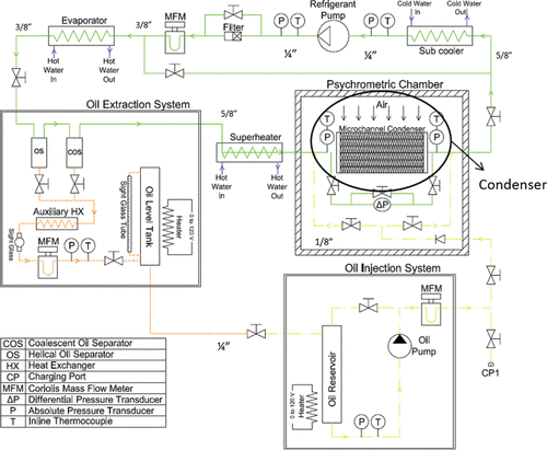
The schematic of the pump-boiler loop of the experimental setup for the OR measurements in microchannel condenser is shown in .
The experimental setup included three main systems, namely a refrigeration loop, an oil injection system, and an oil extraction system. A laboratory small-scale pump-driven refrigerant loop was constructed to control the refrigerant saturation temperature and the refrigerant flow rate to the test section. From the pump, the refrigerant flowed through a Coriolis mass flow meter and then it was directed to tube-in-tube evaporator coils to achieve superheated vapor conditions at the inlet of the oil separators. The refrigerant should be in superheated condition to allow the oil separation from the refrigerant and oil mixture at the oil separators. The evaporator coils were water-heated heat exchangers in which hot water was supplied from a large hot water tank. From the evaporator coils the refrigerant circulated through the refrigerant line to the oil separators. The refrigerant was then directed to a plate heat exchanger that worked as superheater to control the degree of superheat of the refrigerant entering the test section. From the test section, the refrigerant mixture was circulated through plate-type heat exchanger acting as post-condenser and subcooler. At the outlet of the subcooler, the refrigerant was liquid and it was fed back to the pump. The required system pressure and temperature were controlled to the steady-state conditions before each injection test by regulating the temperatures and flow rates of the water in the evaporator coils and of the air stream entering the condenser. In addition, a hydraulic accumulator was installed in the refrigerant line to stabilize the pressure during the oil injection and extraction processes.
The oil injection system consisted of an oil reservoir and a variable speed gear pump to inject metered amount of oil into the test section. Refrigerant vapor was used to pressurize the oil in the oil reservoir, which assisted by decreasing the pressure drop across the oil injection gear pump. The temperature and pressure of the oil reservoir were measured to determine the solubility of refrigerant in the oil that was injected into the test section. This solubility was also experimentally measured with random periodic samples taken from the oil reservoir and analyzed according to the ASHRAE Standard 41.4 (1996). Coriolis mass flow meter measured the injected oil mass flow rate.
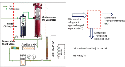
The oil extraction system consisted of two customized refrigerant oil separators, helical-type and coalescence-type separator placed in series, a mass flow meter and oil tanks as depicted in .
Internal floating valves in both oil separators was absent for continuous flow of the oil out of the seperators to the oil tanks. An auxiliary heat exchanger was installed on the oil drain lines of the seperator to further evaporate the refrigerant dissolved in the extracted oil. A special refrigerant dye was mixed with the oil to detect the extracted oil in the sight glass. Coriolis mass flow meter measured the extracted oil mass flow rate. The extracted oil was then stored in two oil tanks equipped with level sight glass indicators. The pressure equalization lines ensured that there was no back pressure build up inside the oil tanks.
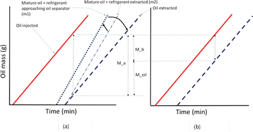
The mass balance of the oil separators depicted in is expressed in EquationEquation 1(1) .
(1) where,
,
, and
are the mass flow rate of refrigerant and oil mixture approaching oil separators, the mixture extracted from oil separators, and the mixture bypassing oil separators, respectively. The efficiency, ϵ in EquationEquation 2
(2) , was determined through a series of preliminary and periodic tests on the oil separators in which the entering mixture had OMF ranging from 1–6 wt.% and it circulated through the oil separators at various pressures and flow rates.
(2)
The oil concentration in the exiting mixture was measured by using the ASHRAE Standard 41.4 (ASHRAE Citation1996) during these preliminary experiments. The efficiency of the oil separators, estimated by using EquationEquation 2(2) , ranged from 95% to 99%. The mass of the oil bypassing the oil separator was accounted for with the oil separator extraction efficiency, EquationEquation 3
(3) .
(3)
The OR experiments were conducted by using this pump-boiler type loop, in which the refrigerant was circulated by a gear pump. The oil was purposely injected in the refrigerant loop at two locations, inlet and outlet of the microchannel condenser (referred to as test section). The principle of the OR measurement procedure is illustrated in .
The amount of oil injected and extracted was measured from the injection and extraction mass flow rates. The amount of refrigerant dissolved in the oil was taken into account based on solubility data from Cavestri and Schafer (2000) for given pressures and temperatures measured in the oil reservoir. At the time to, oil was released to the inlet of the microchannel heat exchanger. The oil flowed through the test section and reached the oil separators where it was extracted from the system. The extracted oil was visually detected at the oil line sight glass at time t1 and, at the same time, a regular step up increase of the oil flow rate measured from the Coriolis flow meter, installed at the bottom of the oil separators in , was recorded. The injection and extraction flow rates became stable and steady at time t2. It should be noted that refrigerant was also present in the liquid mixture flow that was extracted from the refrigerant loop at the oil separators location because both refrigerants R410A and R134a are soluble in POE oil. The solubility of the refrigerant in the oil was accounted for in order to calculate the net amount of POE oil present in the extracted oil rich liquid mixture of POE oil and refrigerant. It should also be emphasized that the extractor efficiency of separation was considered in order to obtain the total amount of oil that entered the oil extractor. From time t2 to time t3, the average difference between the oil mas injected and the oil mass extracted resulted in the oil mass that was held up in the microchannel condenser plus all connecting pipelines downstream the test section and in between the injection port and the oil separators, Ma. With reference to , the amount of oil Ma was measured from the time integral of two oil flow rates as shown in EquationEquation 4(4) .
(4)
A similar procedure was then conducted for the injection test at outlet port of the test section, and the mass of oil retained in the pipelines downstream the test section was measured by using the time integral as shown in EquationEquation 5(5) .
(5) where the symbols t′0 and t′3 indicates the new times at which the oil was released to the outlet port of the test section and at which the flow rate became stable and steady for the injection test at the outlet port of the test section. The average difference between the oil mass injected and the oil mass extracted during the injection test at the outlet port of the test section was the oil mass retained in the connecting pipelines between outlet injection port and the oil separators, Mb. The difference between the two amounts of oil masses resulted in the oil mass that was retained in the test section, Moil,retention, that is,
OR mass in the test section = OR mass in the test section plus in the downstream pipeline – OR mass in the downstream pipeline
At the end of each test, the system oil was flushed using the oil seperators. Two sight glasses were installed before and after the oil separators to detect the presence of any residual oil in the refrigerant loop during the flushing cycles. The flushing was done until no traces of oil, stained with special fluroscent die, were visually observed at the sight glasses. The procedure was successful in cleaning all the significant residual oil held up in the test section, which was confirmed, when the initial heat transfer capacities and refrigerant-side pressure drops of the microchannel heat exchangers were restored after flushing. Insignificant amount of residual oil, even if present inside the test section after each flushing cycle, which might have an effect on the heat transfer rate and pressure drops, was below the sensitivity of the test apparatus.
Test conditions
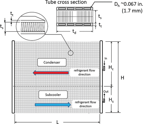
The microchannel condenser test section was a two-pass, aluminum, louvered-fin type heat exchanger. A schematic is given in .
The manufacturer data of the heat exchanger were not available, and the measurements were conducted at Oklahoma State University (OSU) research laboratory, and are summarized in .
Table 1 Microchannel condenser geometry.
The estimated internal volume of the condenser, 149 in3 (2.4 liters, 2,436 cm3), and it was used to normalize the OR measurements. The internal volume was estimated based on the outside envelope dimensions, the wall thickness of the microchannel tubes, and an estimated wall thickness for the headers.
The refrigerant-oil mixture tested were R410A and ISO VG 32 grade mixed acid POE oil and R134a and ISO VG 32 grade mixed acid POE oil. The test conditions matrix is summarized in .
Table 2 Test conditions.
The OMF injected in the refrigerant–oil mixture was varied from 0 to 6 wt.%. The tests were performed at saturation temperatures of 85°F to 130°F (29°C to 54°C) for R410A+POE oil, and 95°F to 130°F (35°C to 54°C) for R134a+POE oil. At the inlet of the test section, the superheated refrigerant vapor had degree of superheat that varied between about 10°F (5°C) for one series of tests and 65°F (36°C) for the second main series of tests. The airside test conditions were changed depending on the refrigerant saturation temperature. For each saturation temperature, the refrigerant mass flow rate were set by regulating the refrigerant gear pump speed to represent part and full load operations of HVAC and refrigeration systems applications.
Data reduction
The amount of oil carried over with the refrigerant in the microchannel heat exchanger is referred to as the OMF, EquationEquation 7(7) .
(7) where,
and
are the injected oil injection flow rate and the circulating refrigerant flow rate, respectively. The amount of OR is calculated using EquationEquation 8
(8) .
(8) where, Moil, retention is calculated form EquationEquation 6
(6) and ρ is the density of the oil at reference temperature of 68°F (20°C). The OR inside the microchannel heat exchanger was measured according to the procedure described in the experimental setup. The dimensionless normalized OR volume, ORVN, is calculated as the ratio of the oil volume retained in the heat exchanger to the internal volume of the microchannel heat exchanger, MCHXvolume, EquationEquation 9
(9) .
(9)
The OR in the test section increases with increase in OMF. The amount of OR in the microchannel heat exchanger offers an additional resistance to refrigerant flow. Consequently, the pressure drops depend upon the refrigerant flow rate and on the OMF in the circulating refrigerant–oil mixture (Cremaschi et al. Citation2005). The refrigerant-side pressure drop at the measured OMF, ΔPwith oil was compared to the corresponding pressure drop across the test section at the same total mass flow rate but with no oil present, ΔPwithout oil. The pressure drop factor (PDF) was used to represent the effect of the oil, EquationEquation 10(10) .
(10)
Similarly, the microchannel heat exchanger heat transfer capacity factor (HTF) was calculated based on the heat transfer capacity measured during the test with oil and the corresponding test with same operating conditions without oil, EquationEquation 11(11) .
(11) where,
is the heat transfer capacity measured on the air side of the heat exchanger.
The measurement uncertainty of the and error propagation calulations were based on the analysis described by Taylor and Kuyatt (Citation1994), and the values are listed in .
Table 3 Experimental uncertainties.
Table 4 Legend of the letters and symbols used in the figures reporting the tests results of microchannel condenser with R410A and POE.
Experimental results
The experimental results of OR, pressure drop and heat transfer factor of R410A+POE oil mixture and of R134a+POE oil mixture in microchannel condenser are presented and discussed in the following section.
OR in the microchannel type condenser
Condenser OR for AC applications with refrigerant R410A and POE oil
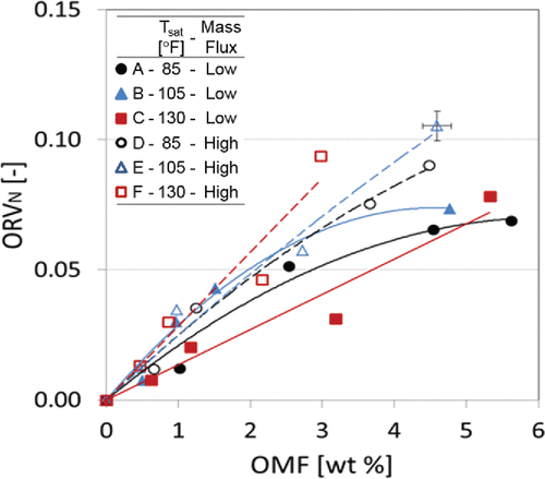
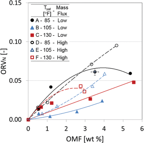
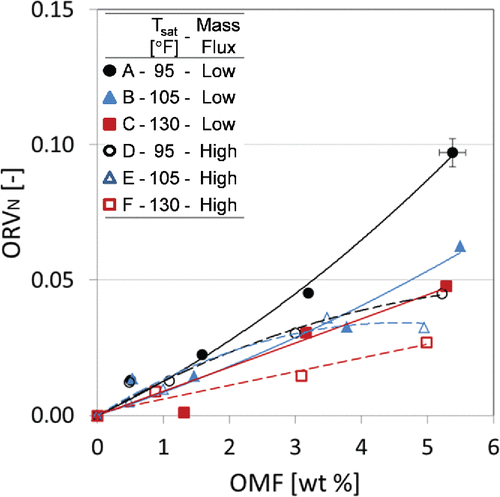
The results of OR in the microchannel condenser for AC applications with refrigerant R410A+POE lubricant mixture are shown in and . with summarized legends in .
The oil retention volume was normalized (ORVN) with respect to the condenser internal volume and it was plotted versus OMF for each saturation temperature and each mass flux studied in the present work. The degree of superheat at the inlet of microchannel condenser was set to 10°F (∼5°C) in , which was referred to as low degree of superheat, and to 65°F (∼36°C) in , which was referred to as high degree of superheat throughout these sections of the manuscript. The results indicated that the oil retained in the condenser was strongly dependent on the OMF in the heat exchanger. The OR volume increased if the OMF increased and it was measured up to 11% of the condenser internal volume, which consisted of the internal volume of all microchannel tubes plus the headers.
and show that the OR volume for high mass flux conditions are higher than those for low mass flux conditions. The effect of mass flux on the OR was small for low OMFs and becomes more evident for OMFs higher than 3 wt.%. The OR volume was from 1.6 to 3 times higher for the cases of high mass flux compared to those of low mass flux cases.
For similar mass flux, the effects of saturation temperature on the OR were small for low superheat inlet condition (see ). The most marked effect of the refrigerant mass flux on the OR volume was observed for the test at low superheat condition and Tsat = 130°F (54°C), and it is reported in with the series C and F. An increase of the mass flux from 16 to 24 lbm/ft2-s (80 to 120 kg/m2-s) doubled the OR volume in the microchannel condenser. This can be explained by considering that at high refrigerant mass flux more liquid phase was present inside the condenser than at low mass flux because the airside entering conditions were kept constant between the two series of tests. The liquid phase traveled along the condenser with lower mass velocity with respect to the refrigerant vapor phase velocity. If more liquid was present inside the condenser, the oil content increased because the concentration of the oil in the mixture was constant (for example looking at constant OMF line of 3 wt.% for the series at high and low mass flux).
When the saturation temperature increased, the miscibility of R410A+POE oil mixture decreased until the critical solution temperature could be reached and the mixture became completely immiscible. The critical solution temperature of R410A+POE oil mixture at high refrigerant mass fraction of about 0.8 (which is equivalent to OMF of 20 wt.%) was about 113°F (45°C; Kang and Pate Citation1999). At saturation temperature of 130°F (54°C), a decreased degree of miscibility of POE oil in R410A liquid refrigerant occurred with respect to the other (much lower) saturation temperatures tested in the present work. Because of this decreased miscibility, an increase in viscosity of the liquid phase occurred, especially near the internal walls of the condenser tubes. In addition, at high mass flux of refrigerant–oil mixture, more oil mass was injected during the test period into the heat exchanger in order to set the OMF. Because of the reduced liquid phase velocity and of the augmented liquid viscosity, more oil can potentially be held up inside the microchannel condenser.
If it is assumed that the liquid phase formed a distinct layer separated from the vapor phase inside the microchannel tubes when the mixture undergoes the two phase flow change process and inside the inlet headers of the condenser, then a low degree of superheat of the entering refrigerant vapor resulted in a lower superficial velocity when compared to the similar tests with high degree of superheat. This contributed to increase the OR volume because carrying the oil became more difficult when the refrigerant vapor had low superficial velocity and when the oil was less miscible with the liquid refrigerant. That was the case when saturation temperature was 130°F (54°C) and the degree of superheat was low, as that for the series C and F in .
Table 5 Legend of the letters and symbols used in the figures reporting the tests results of microchannel condenser with R134a and POE.
Different trends were observed for high superheat inlet conditions, shown in . The OR volume decreased as the saturation temperature increased and for both low and high mass fluxes. At high superheat conditions, most of the condenser internal volume was filled with refrigerant and oil in the two phase flow and the initial entering section of the condenser had superheated vapor. Because the degree of superheat was high, there was less liquid refrigerant in the internal volume of the condenser and the dominant effect for OR was not the miscibility of oil in the refrigerant liquid anymore.
By comparing the OR volume in with the corresponding data in , it can be deduced that at Tsat of 105°F (41°C) the OR volume was higher when the refrigerant inlet condition of the condenser was at lower degree of superheat. In this condition, the refrigerant in the condenser internal volume was predominantly in two-phase flow and the refrigerant vapor had lower superficial velocity in average when entering with low degree of superheat. The superficial gas velocity, vsg, was calculated according to EquationEquation 12(12) :
(12) that is, the ratio between mixture mass flow rate,
, and total cross-sectional free flow area of the microchannel tubes, A, and the density of the refrigerant vapor, ρg. For example, at Tsat of 105°F (41°C) the superficial vapor velocity of the refrigerant entering the condenser was about 2.7 ft/s (0.8 m/s) for the low degree of superheat case and low mass flux (solid triangles data points with letter B in ). This velocity increased to 3.3 ft/s (1.0 m/s) for the corresponding case of high degree of superheat and for same mass flux in the solid triangles data points with letter B in . This increase of the refrigerant vapor velocity reduced the OR volume inside the condenser. It should be noticed that the oil existed as either homogenous solution in liquid refrigerant or as a separate layer of oil-rich film at the microchannel tube wall. The presence of oil on both cases promoted oil held up in the microchannel condenser but in different ways. The two-phase region of the condenser was the main part where the oil was retained and oil was a component of the liquid phase mixture. The higher was the liquid phase volume inside the condenser, the higher was the oil retained in it. On the other hand, in the superheated section of the condenser, oil existed as liquid droplets and as film near the wall. The higher was the refrigerant vapor velocity, the higher was the oil carry over with it. The total oil volume retained in the condenser depended on those two mechanisms, and the dominant mechanism varied for the saturation temperatures investigated in the present work. While a low degree of superheat tended to increase the OR, as reported in the data of with respect to that of , a generalization of this result to all saturation temperatures of the present work should not be made. For example, by comparing the OR data of series B, at OMF of 3 wt.% the ORVN is about 0.07 with low degree of superheat in and it is reduced to 0.02 with high degree of superheat in . However, the OR at Tsat = 85°F (29°C) was basically the same for both low and high degree of superheat cases, as shown in the series A and D of the two figures.
Condenser OR for refrigeration applications with refrigerant R134a and POE oil
The results of OR in microchannel condenser for refrigeration applications with refrigerant R134a + POE oil mixture are shown in . Test conditions are represented by open and full symbols and letters A to F summarized in .
The OR volume was normalized with respect to the condenser internal volume (ORVN), and it was plotted versus OMF for each saturation temperature and each mass flux studied in the present work. The degree of superheat at the inlet of microchannel heat exchanger was 65°F (36°C). The experimental results of indicated that the oil retained in the condenser was strongly dependent on the OMF. The OR volume increased if the OMF increased and for refrigerant R134a + POE mixture it was measured up to 10% of the condenser internal volume.
By comparing and , the OR volume for both R410A + POE oil and R134a + POE oil are strongly dependent on OMF and have maximum OR at the lowest saturation temperature. With refrigerant R134a + POE oil, the effect of refrigerant mass flux on OR was small for OMF below 2 wt.% and the oil held in the condenser was less than 3% of condenser internal volume (). This was not the case with R410A + POE oil where the mass flux effect was already important at OMF about 1 wt.% (see again for OMF of 1 wt.% and compare with at OMF of 1 wt.%).
It can also be seen from that at the same condensation temperature, the increase mass flux decreased OR volume with R134a+POE oil (series with solid line and dashed line). However, the opposite was observed for R410A+POE oil as depicted in .
If the OMF increased to above 3 wt.%, the high mass flux data (dashed lines in ) had lower OR than the corresponding low mass flux data (solid lines in ) for all three saturation temperatures tested in the present work. At low condensation saturation temperature of 95°F (35°C), OR increased quite significantly if the mass flux decreased, as represented by the series with letters A and D in . For these series, at OMF of 5 wt.%, the OR increased by about 50% if the mass flux of the condenser section decreased from 18 lbm/ft2-s (88 kg/m2-s) to 10 lbm/ft2-s (49 kg/m2-s).
The lowest OR volume for R134a+POE oil was observed at highest saturation temperature and mass flux of 130°F (54°C) and 18 lbm/ft2-s (88 kg/m2-s), respectively (Series F). This can be explained with the high refrigerant–oil solubility at high temperature and coupled with high mixture velocity due to high mass flux.
Effect of OR on the HTFs of the condenser
As described in the data reduction section, the HTF of the refrigerant and POE oil mixture was defined as the ratio of the measured heat transfer rate of the microchannel condenser when oil was retained inside the heat exchanger over the heat transfer rate of the microchannel condenser for the case when there was not any oil inside the heat exchanger. Both heat transfer rates were measured at similar total mass flow rate, for example, the refrigerant flow rate entering the condenser in the case with no oil was similar to the mixture (refrigerant plus oil) mass flow rate in the cases with oil. This means that the refrigerant flow rate was decreased slightly down 4% to 5% when OMF increased from 0 to 5 wt.%. The saturation pressures of condensation were also the same between the case with no oil and the tests with oil. And the degree of superheated vapor refrigerant entering the condenser was a third variable kept constant in between the two test. Finally, the air inlet temperature and velocity were also constant between the cases of tests with oil and the baseline references with no oil. In other words, by comparing the heat transfer rates at same flow rate, pressure, and superheat, the HTF is a performance parameter that isolated and quantified the effect that oil retained inside the condenser had on the microchannel condenser refrigerant-side total heat transfer rate.
Condenser HTF for AC applications with refrigerant R410A and POE oil
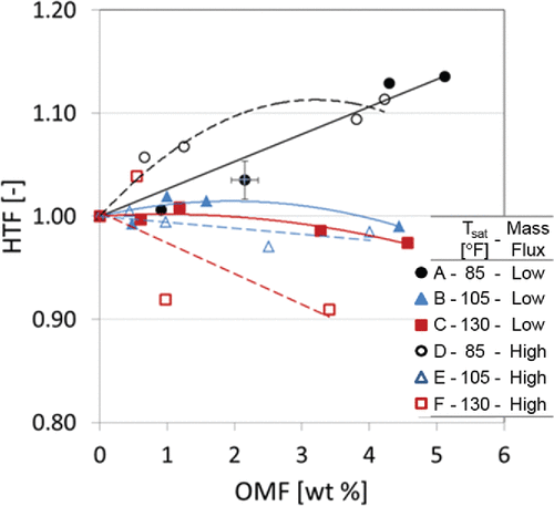
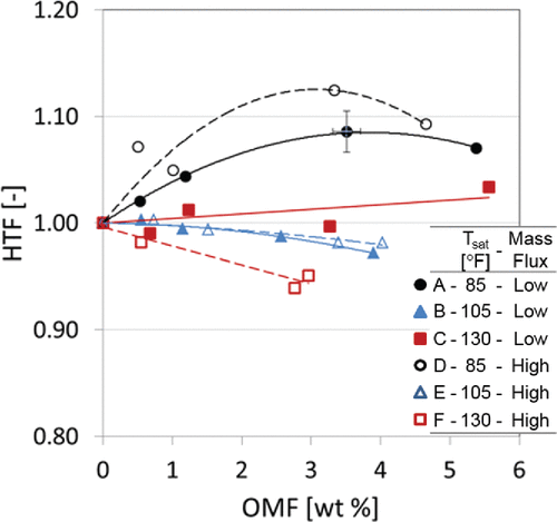
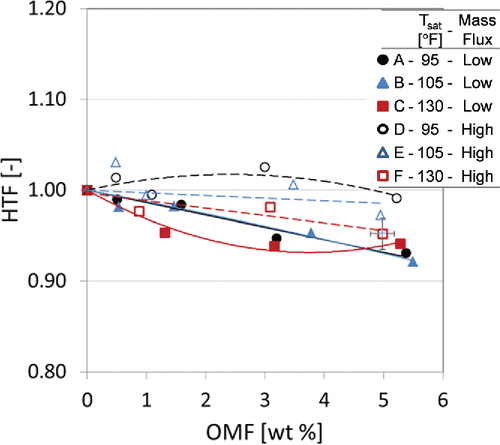
When OMF is 0 (i.e., no oil), the HTF was 1 by its own definition and it varied with OMF as shown in and for the microchannel condenser investigated in the present work.
The test conditions are represented by open and full symbols and letters A to F as summarized in . At high saturation temperatures (cases with letters C and F), the HTF decreased if the OMF increased. Different trends were observed for medium saturation temperature and most intriguing results were observed at low saturation temperatures for both refrigerant mass fluxes and inlet superheat conditions (tests A and D). For medium saturation temperature of 105°F (41°C), indicated as B and E in the figures, the refrigerant-side heat transfer capacities seemed to be independent of the OMF for both mass fluxes and superheat inlet conditions. It is interesting also to note here that at low saturation temperature, the presence of oil was observed to increase the refrigerant-side heat transfer rate, although in nonmonotonic fashion. The HTF in these conditions increased slightly as the OMF increased to about 3 wt.%; then the HTF started to decline at higher OMFs. POE oil did not change phase during the condensation process and it did not have as good heat transfer properties as that of refrigerant R410A. POE oil was a contaminant that added an additional thermal resistance to the heat exchange process between the air and the refrigerant in the microchannel condenser. Thus, the result of HTF decreasing when OMF increased could be somewhat intuitive because if POE oil was present in the two-phase flow mixture, then the convective heat transfer coefficient of the refrigerant-side was expected to diminish.
On the other hand, the tendency of the HTF to increase if OMF increased to 3 w.t.% or more was unexpected. For several tests, which were conducted in different days and repeated several times, and particularly for low saturation temperature of 85°F (29°C), both series A and D in and indicated that the presence of oil augmented the refrigerant-side heat transfer rate.
The effects of refrigerant mass flux on the heat transfer rate had different results that were dependent on saturation temperature. At low saturation temperature, the HTF was slightly higher for high mass flux compared to that of low mass flux as shown in both figures (cases A and D). On the other hand, at high saturation temperature and for a given OMF (for example at OMF of 3 wt.% and for the series C and F), the HTF decreased if the mass flux increased. This behavior was not observed at saturation temperature of 105°F (41°C), for which the HTF was not affected by the change of mass flux (see HTFs for the series B and E). The effect of refrigerant mass flux on the condensation heat transfer of refrigerant and oil mixtures was also reported to be small in the article of Shao and Granryd (Citation1995), in which they tested R134a+PAG oil mixture. The authors reported that for three different mass fluxes and for OMF up to 5 wt.%, there was no considerable change on the refrigerant-side heat transfer rate.
Shao and Granryd (Citation1995) findings agreed with the results of the present work from the test series B and E, that is, only for one saturation temperature of 105°F (41°C). This is a common reference used in AC applications. However, in the present work, the effect of oil on heat transfer rate depended on the saturation pressure of condensation. The HTF decreased as the saturation temperature increased. The degradation of heat transfer capacity can be attributed to the augmentation of the liquid mixture viscosity of refrigerant–oil mixture compared to that of pure refrigerant R410A. Based on the viscosity analysis of the R410A+POE oil mixture as reported by Zhang and He (Citation2009), the liquid mixture kinematic viscosity for the experiments of the present work increased by over 28% for the range of saturation temperatures tested in their work. The higher viscosity, along with the higher surface tension of the liquid refrigerant–oil mixture reduced the molecular and turbulent transport in the condensate film, hence decreasing the condensation heat transfer. This effect was further augmented by the annular flow regime that is typically established inside microchannel tubes.
At low saturation temperature, the presence of oil increased the heat transfer capacity for low OMFs. Again, similar results were also reported in the open domain literature by Shao and Granryd (Citation1995) with R134a+PAG mixture. A possible reason for this observation is that the refrigerant–oil mixture had higher condensation temperature compared to that of pure refrigerant. This was also confirmed using vapor pressure correlation suggested by Jeng et al. (Citation2001) for R410A+POE oil mixture for the tests of the present work. At the same ranges of saturation pressure, the saturation temperature for the refrigerant and oil mixture at OMF of 5wt.% was up to 1.4°F higher than that of refrigerant R410A only. The higher saturation temperature caused the mixture to condense earlier at the beginning of microchannel condenser and increased the overall heat transfer capacity of the condenser.
The test results at high degree of superheated vapor at inlet of the condenser had slightly higher HTF than the corresponding tests at low degree of superheated vapor. In other words, the reduction of the refrigerant-side heat transfer rate due to OR was smaller when the refrigerant entered the condenser with high degree of superheated vapor. This result was associated with lower OR volume when high superheated vapor entered the condenser. In the superheated section of the condenser, oil was present as liquid droplets entrained in the refrigerant vapor bulk flow and as oil-rich liquid film at the tube wall interface. Less oil in the superheated section of the condenser yielded to convective heat transfer process inside the microchannel tubes that was similar to that of refrigerant only case. Since the refrigerant-side heat transfer rate of the superheated section of the condenser was secondary to the heat transfer rate of the phase change section of the condenser, the higher was the superheated vapor, the lesser was the OR volume, and the lesser was the penalization of the heat transfer rate when oil was present.
Condenser HTF for refrigeration applications with refrigerant R134a and POE oil
Refrigerant R134a+POE oil mixture was tested for refrigeration applications and the effects of oil on the refrigerant-side heat transfer rate of the microchannel condenser are shown in .
Test conditions are represented by open and full symbols and letters A to F summarized in . When OMF is 0 (i.e., no oil), the HTF was 1 by its own definition and for R134a+POE mixture, the HTF varied with OMF as shown in for the microchannel condenser investigated in the present work. For all cases except for low saturation temperature of 95°F (35°C) and high mass flux, the HTF decreased as the OMF increased.
The presence of oil in the condenser reduced the heat transfer rate and the penalty was fairly significant at low refrigerant mass flux. These findings were consistent with the previous results on the OR where low refrigerant mass flux resulted on higher OR. The oil retained in the form of a liquid-rich layer inside the microchannel condenser hindered the convective heat transfer exchange between the refrigerant and internal walls of the heat exchanger. The heat transfer capacity penalization was less than 10% at the highest saturation temperature tested in the present work.
It is interesting also to note here that at low saturation temperature of 95°F (35°C), indicated as D, the presence of oil was observed to slightly increase the refrigerant-side heat transfer rate, although this increase was considered within the experimental uncertainty of the measurements. The HTF in these conditions increased slightly by up to 3% as the OMF increased to about 3wt.%; then the HTF started to decline at higher OMFs.
PDFs of the condenser
Condenser PDF for AC applications with refrigerant R410A and POE oil
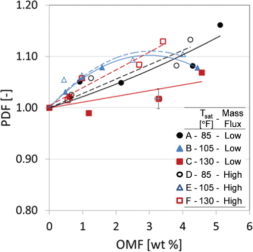
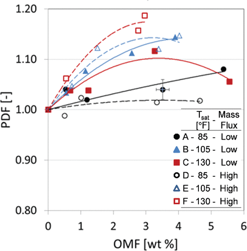
As described in the data reduction section, as the parameter that isolated and quantified the effect of oil that was retained inside the condenser on the refrigerant-side pressure drop across the entire condenser. When OMF was 0 wt.% (i.e., no oil), the PDF was 1 by definition and it varied with OMF as shown in and .
The figures indicate that the PDF increased if OMF increased. Up to 19% increase of pressure drop was measured at Tsat = 130°F (54°C) with high inlet superheat of the condenser. The increasing pressure drop with oil presence can be attributed to high refrigerant–oil mixture viscosity compared to that of refrigerant only. This increase of viscosity increased the shear stress and the frictional pressure drop associated with it. The increase of OMF also introduced higher amount of OR in the microchannel and it reduced the flow cross-sectional area for the refrigerant vapor. This led to increasing pressure drop during the condensation process. Another reason for the pressure drop increase was the predominant annular flow established in microchannel during flow condensation (Schlager et al. Citation1987). For annular flow, the increasing refrigerant–oil mixture viscosity increases the shear stress significantly compared to that of other flow regimes, such as stratified flow and wavy flow types.
As indicated in both figures, the pressure drop increased as the refrigerant mass flux increased although with varying magnitude. Both figures show that the effects became more important as OMF increased to about 3 wt.%. A significant rise of pressure drop was observed with the increase of refrigerant mass flux at high saturation temperature (case C and F in both figures), while the results showed smaller effects for other conditions. In the same figure, at saturation temperature of 130°F (54°C), the PDF at low mass flux (case C) was approximately 10% higher when OMF was 3 wt.% compared to that of without oil case, and the PDF doubled for high mass flux (case F). It is interesting to note that at this higher saturation temperature, the effect of refrigerant mass flux became more important although the viscosity of R410A+POE oil mixture decreased (Zhang and He Citation2009).
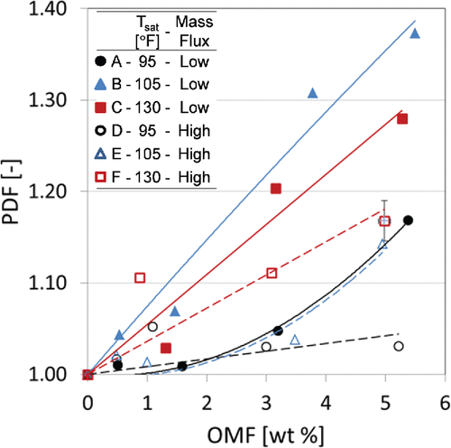
It seems that the pressure drop during this condition was mainly affected by the oil-rich film that was separated and retained in the microchannel due to immiscibility of the mixture at higher saturation temperature (Kang and Pate Citation1999). This observation was also confirmed by the findings that for the above conditions (case C and F in ), both pressure drop and OR results showed positive relation, for example, when the OR increased, the measured PDF also increased. The oil-driven viscosity augmentation of the refrigerant-oil mixture and the presence of OR near the microchannel wall contributed to the increase in the PDF.
The effect of saturation temperature on PDF low superheat inlet conditions was small. While for high superheat inlet condition, as depicted in , the increase of saturation pressure increased the PDF, the PDF for saturation temperatures of 105°F and 130°F (41°C and 54°C) were comparable and a significantly lower PDF was observed for lower saturation temperature of 85°F (29°C).
The effect of superheat inlet condition on pressure drop can be observed by comparing data on with the corresponding symbol/letter in . First, the superheat effects on PDF were not monotonic. At low saturation temperature (cases A and D), an increase of the degree of vapor superheat at the inlet of the condenser caused the PDF to decrease, while the opposite behavior was observed for the highest saturation temperature (see series C and F). Finally, the PDF for intermediate saturation temperature of 105°F (41°C) were not significantly altered by the variation of the superheat degree of the refrigerant vapor entering the condenser.
Condenser PDF for refrigeration applications with refrigerant R134a and POE oil
As depicted in , the oil presence significantly penalized the refrigerant-side pressure drop in the microchannel condenser when refrigerant R134a + POE were used.
Although there was some scattering of the pressure drop data, shows that even small OMFs of 1 wt.% can increase the PDF from 1.01 up to 1.10, that is, that even small amount of oil in the refrigerant flow increased the pressure drop from about 1% up to 10%. The effects were more marked at lower refrigerant and oil mass flux. These results were consistent with the OR volume test results, presented previously in , where the amount of oil retained was higher for lower mass flux. While at OMF of 3 wt.% the PDF ranged from 1.03 up to 1.20 (i.e., up to 20% increase of pressure drop due to the presence of excessive oil inside the microchannel condenser), the maximum PDF in the microchannel condenser tested in the present work was 1.37, and it was measured for OMF of about 5 wt.%.
Conclusions
The accumulation and retention of oil inside microchannel type condensers can cause a decrease in heat transfer rate and an increase of pressure drop. Both effects penalize the energy conversion efficiency of air-conditiong systems and of refrigeration systems. In addition, if excessive lubricant is held in the condensers then improper lubrication inside the compressors can often lead to compressors mechanical failure. As a result, it is critical to estimate the OR in this type of condenser technolgy and the effects of the amount of oil retained in the condenser on the heat transfer rate performance and on the pressure drop. This article focuses on quantifying these estimates for a microchannel type condenser commonly used in AC systems and in refrigeration systems. Refrigerants R410A and R134a mixed with POE oil were studied at saturation temperature from 85°F to 130°F (29°C to 54°C), and OMF that was varied from 0 to 6 wt.% in controlled conditions in laboratory and that replicated actual operating conditions of the condenser in AC and refrigeration systems.
For the microchannel type condenser, the results from the present work indicated that the oil retained in the condenser was strongly dependent on the OMF of the mixture. The OR volume increased if the OMF increased and it was measured up to 11% of the condenser internal volume, which consisted of the estimated internal volume of all microchannel tubes plus the headers. The OR volume for high mass flux conditions were higher than those for low mass flux conditions and the effect of mass flux on the OR was small for low OMFs but it became more evident for OMFs higher than 3 wt.%.
Oil affected the heat transfer rate of the microchannel condenser and it penalized the heat transfer capacity by as much as 10% if the OMF was 3 wt.%. Different trends were observed for medium saturation temperature and intriguing results were observed at low saturation temperatures for two refrigerant mass fluxes and inlet superheat conditions. For medium saturation temperature of 105°F (41°C) the refrigerant-side heat transfer capacities were fairly constant, even when a lot of oil was retained inside the condenser, that is, oil occupied up to 11% of the condenser internal volume. These results were observed for two mass fluxes and two level of superheated vapor at the inlet of the condenser. It is interesting also to note that at low saturation temperature of 85°F to 95°F (29°C to 35°C), the presence of oil was observed to increase the refrigerant-side heat transfer rate, although in non-monotonic fashion. For both refrigerant R410A+POE mixture and refrigerant R134a+POE oil mixture, the heat transfer rate at low saturation temperature increased slightly if the OMF increased up to about 3 wt.%; then the heat transfer rate started to decline at higher OMFs. POE oil was a contaminant that added an additional thermal resistance to the heat exchange process between the air and the refrigerant in the microchannel condenser. Thus, the reasons as to why the heat transfer rate of the condenser increased when oil was present at low the saturation temperature of condensation were not clear and required further research in future work.
Oil also increased the refrigerant-side pressure losses of the microchannel condenser up to 19% with relative to oil-free conditions. This was due to high refrigerant–oil mixture viscosity compared to that of liquid refrigerant for the flow inside the microchannel tubes. The increase of OMF also resulted in OR in the microchannel condenser and the oil might have completely blocked some of the channels or at least reduce the refrigerant flow cross-sectional area in the condenser. Both phenomena led to larger pressure drops during the condensation process inside the microchannel type heat exchanger.
References
- ASHRAE. 1996. ANSI/ASHRAE Standard 41.4-1996 (RA 2006)—Standard Method for Measurement of Proportion of Lubricant in Liquid Refrigerant (ANSI Approved). Atlanta: ASHRAE.
- Bandarra-Filho, E.P., L. Cheng, and J.R. Thome. 2009. Flow boiling characteristics and flow pattern visualization of refrigerant/lubricant oil mixtures. International Journal of Refrigeration 32(2):185–202.
- Bai, X., and T.A. Newell. 2002. Investigation of two-phase viscous liquid flow. 9th Int. Refrigeration and Air Conditioning Conference at Purdue. P. Univ. West Lafayette, IN, July 16–19.
- Biancardi, F.R., H. Michels, T. Sienel, and D. Pandy. 1996. Study of Lubrication Circulation in HVAC Systems—ARTI MCLR Project Number 665-53100, DOE/CE/23810-71 The Air Conditioning and Refrigeration Technology Institute, ARTI. East Hartford, CT: United Technologies Research Center (UTRC).
- Cavestri, R.C. and W.R. Schafer. 2000. Measurement of Solubility, Viscosity, and Density of R-410A Refrigerant/Lubricant Mixtures. ASHRAE: Dallas, TX.
- Cremaschi, L., Y. Hwang, and R. Radermacher. 2005. Experimental investigation of oil retention in air conditioning systems. International Journal of Refrigeration 28(Compendex):1018–28.
- Gidwani, A., M.M. Ohadi, and M. Salehi. 1998. In-tube condensation of refrigerant and refrigerant-oil mixtures—A review of most recent work. Proceedings of the 1998 ASHRAE Winter Meeting. Part 1 (of 2), San Francisco, CA, January 18–21, 1998.
- Huang, X., G. Ding, H. Hu, Y. Zhu, H. Peng, Y. Gao, and B. Deng. 2010a. Influence of oil on flow condensation heat transfer of R410A inside 4.18 mm and 1.6 mm inner diameter horizontal smooth tubes. International Journal of Refrigeration 33(1):158–69.
- Huang, X., Y. Zhu, G. Ding, Y. Gao, H. Hu, and B. Deng. 2010b. Two-phase frictional pressure drop characteristics of R410A-oil mixture flow condensation inside 4.18 mm and 1.6 mm I.D. horizontal smooth tubes. HVAC&R Research 16(4):453–70.
- Jeng, Y.-R., C.-S. Chang, and C.-C. Wang. 2001. Vapor pressure of R-410A/oil and R-407C/oil mixtures. Applied Thermal Engineering 21(8):863–70.
- Jin, S., and P. Hrnjak. 2013. Refrigerant and lubricant distribution in MAC system. SAE International Journal of Passenger Cars–Mechanical Systems 6(2):1013–20.
- Jin, S., and P. Hrnjak. 2014. An Experimentally Validated Model for Predicting Refrigerant and Lubricant Inventory in MAC Heat Exchangers. SAE 2014 World Congress & Exhibition, Detroit, MI, April 8–10.
- Kang, H.-M., and M.B. Pate. 1999. Miscibility comparison for three refrigerant mixtures and four component refrigerants. ASHRAE Annual Meeting, Seattle, WA, June 18–23, 1999.
- Lee, J.-P., Y. Hwang, R. Radermacher, and S.S. Mehendale. 2001. Experimental investigations on oil accumulation characteristics in a vertical suction line. 2001 ASME IMECE, New York, USA, November 11–16, 2001.
- Li, H., and P. Hrnjak. 2013. Effect of lubricant on two-phase refrigerant distribution in microchannel evaporator. International Journal of Material and Manufacture 6(3):567–75.
- Mehendale, S.S., and R. Radermacher. 2000. Experimental and theoretical investigation of annular film flow reversal in a vertical pipe: Application to oil return in refrigeration systems. HVAC&R Research 6(1):55–74.
- Radermacher, R., L. Cremaschi, and R.A. Schwentker. 2006. Modeling of oil retention in the suction line and evaporator of air-conditioning systems. HVAC&R Research, 12(1):35–56.
- Riedle, K.J., N.A. Macken, and S.W. Gouse Jr. 1972. Oil transport by refrigerant vapor: A literature survey and proposed analytical model. ASHRAE Transactions 78(Part 2):124–34.
- Schlager, L.M., M.B. Pate, and A.E. Bergles. 1987. Survey of Refrigerant Heat Transfer and Pressure Drop Emphasizing Oil Effects and in-Tube Augmentation. New York, NY: ASHRAE.
- Schlager, L.M., M.B. Pate, and A.E. Bergles. 1990. Oil quantity measurements in smooth and micro-fin tubes during evaporation and condensation of refrigerant-oil mixtures. ASHRAE Annual Meeting, St. Louis, MO, June 9–13.
- Schubring, D., E.T. Hurlburt, A.C. Ashwood, and T.A. Shedd. 2009. Optical Measurement of Base Film Thickness in Annular Two-Phase Flow. Jacksonville, FL: American Society of Mechanical Engineers.
- Shao, D.W., and E. Granryd. 1995. Heat transfer and pressure drop of HFC134a-oil mixtures in a horizontal condensing tube. International Journal of Refrigeration 18(8):524–33.
- Shedd, T.A., and T.A. Newell. 1998. Automated optical liquid film thickness measurment method. Review of Scientific Instruments 69(12):4205–13.
- Shedd, T.A. and T.A. Newell. 2004. Characteristics of the liquid film and pressure drop in horizontal, annular, two-phase flow through round, square and triangular tubes. Journal of Fluids Engineering Transaction 126(5):807–17.
- Shen, B., and E.A. Groll. 2005a. Review article: A critical review of the influence of lubricants on the heat transfer and pressure drop of refrigerants, part II: Lubricant influence on condensation and pressure drop. HVAC&R Research 11(4):511–26.
- Shen, B., and E.A. Groll. 2005b. Review article: A critical review of the influence of lubricants on the heat transfer and pressure drop of refrigerants, part 1: Lubricant influence on pool and flow boiling. HVAC&R Research 11(3):341–59.
- Sundaresan, S.G., and R. Radermacher. 1996. Oil return characteristics of refrigerant oils in split heat pump system. ASHRAE Journal 38(8):57–61.
- Taylor, B.N., and C.E. Kuyatt. 1994. Guidelines for Evaluating and Expressing the Uncertainty of NIST Measurement Results. Gaithersburg, MD: U.S. Department of Commerce, Tech. Adm., NIST; 20.
- Thome, J.R. 1995. Comprehensive thermodynamic approach to modeling refrigerant-lubricating oil mixtures. HVAC&R Research 1(2):11025.
- Vaughn, R.S. 1971. Refrigerant compressors, lubricating oil, and refrigerant—An uneasy trio. ASHRAE Symposium Bulletin 1:14–8.
- Wang, C.C., A. Hafner, C.S. Kuo, and W.D. Hsieh. 2012. An overview of the effect of lubricant on the heat transfer performance on conventional refrigerants and natural refrigerant R-744. Renewable & Sustainable Energy Reviews 16(7):5071–86.
- Youbi-Idrissi, M., and J. Bonjour. 2008. The effect of oil in refrigeration: Current research issues and critical review of thermodynamic aspects. International Journal of Refrigeration 31(2):165–79.
- Zhang, Y., and M. He. 2009. Kinematic viscosity of R410A and R407C refrigerant−oil mixtures in the saturated liquid phase with lubricant mass fraction in the range of (0 to 0.0001). Journal of Chemical & Engineering Data 55(8):2886–9.

