Abstract
Many automated fault detection and diagnostics methods have been developed for application to building mechanical systems over the past 20 years because they have the potential to reduce operating costs and energy consumption by providing early warning of performance degradation faults. Supermarkets could be a very beneficial setting to deploy automated fault detection and diagnostics, particularly in the refrigeration systems, which are major energy users and are known to commonly suffer from significant refrigerant leakage problems. The current article provides an overview of the common mechanical systems deployed in supermarkets, and then describes a comprehensive review of the literature on automated fault detection and diagnostics methods from other systems that could potentially be applied in supermarket settings. A collection of supermarket field data is analyzed in the context of its potential use in automated fault detection and diagnostics methods from other systems. The review includes methods to categorize and assess the automated fault detection and diagnostics approaches, from the perspective of a potential adopter of automated fault detection and diagnostics technology for a supermarket setting. The article concludes that supermarket automated fault detection and diagnostics is still in the early stages of development and that there is a need to further develop automated fault detection and diagnostics methods for supermarket applications. To facilitate the development of supermarket-specific automated fault detection and diagnostics approaches, additional data sets from refrigeration equipment are needed.
Introduction
The emergence of the modern supermarket traces back almost a century (Hamlett et al. Citation2008). In the United States, there are about 200,000 grocery stores, including supermarkets, convenience, and small grocery stores (DOE Citation2012). According to the Commercial Building Energy Consumption Survey (CBECS), the energy usage intensity (EUI) of food sales category buildings is typically about 200 (631
), which is among the top three energy-intensive building categories (CBECS Citation2006). Supermarket refrigeration has the largest end-use electricity consumption in comparison to other store end-use categories (EnergyStar Citation2008). There are significant energy and operating cost-saving potentials through early detection and diagnosis of faults in these systems (Dong et al. Citation2013). The potential energy savings of automated fault detection and diagnostics (AFDD) and commissioning for all the major energy-consuming building systems and equipment is estimated to be between 5% and 15% (Brambley et al. Citation2005).
More AFDD methods have been developed for air-conditioning systems and chillers than commercial refrigeration systems (Wichman and Braun Citation2009). Although the basic refrigeration cycles are similar, supermarket equipment and air-conditioning systems vary in many aspects (Wirz Citation2009). A typical supermarket refrigeration system contains 3000 to 5000 lb (1361 to 2268 kg) of refrigerant in a closed circuit (Walker and Awarded Citation2001). It is estimated that an average 15%–20% of the refrigerant in each store is lost annually due to leakage (Assawamartbunlue and Brandemuehl Citation2006). A faulty system may cause energy waste, excessive equipment wear or compromise the food quality (Fisera and Stluka Citation2012). The maintenance and operational costs associated with supermarket operations, and the narrow supermarket net profits of 1%–2% (FMI Citation2013), have drawn increasing attention to the use of AFDD methods in this sector (Taylor et al. Citation2002; Yang et al. Citation2011a, Citation2011b).
Recent supermarket AFDD developments address HVAC and refrigeration systems (Mavromatidis et al. Citation2013; Srinivasan et al. Citation2015; Thybo and Izadi-Zamanabadi Citation2004; Yang et al. Citation2011a, Citation2011b), as well as the lighting system (Mavromatidis et al. Citation2013). These references stem from both industry and academic research of lighting, HVAC, and refrigeration systems.
Supermarket systems are independently controlled, but they are physically interconnected (Ge and Tassou Citation2011). For instance, a 5% reduction in the store relative humidity can reduce the total store energy consumption by 5% (Bahman et al. Citation2012).
The present article explores the scientific literature and patent documents to identify the existing AFDD for supermarket applications, summarizes the findings, and shows that there is no overall energy system AFDD that considers the interaction of the sub-systems in a holistic manner. Furthermore, the adaptability of some of the characteristic features used in HVAC AFDD—condenser split, liquid line subcooling, and evaporating temperature—on supermarket equipment is investigated.
The current article is organized as follows. First, an overview of common supermarket equipment is presented. Second, the processes of fault detection and diagnosis of supermarket equipment from research literature and patent documents are summarized. Third, the adaptability of some of the commonly used characteristic features in HVAC AFDD methods to supermarket equipment is investigated. The last section provides recommendations for future research and underscores the need to develop new AFDD for supermarket application.
Supermarket equipment
Supermarket equipment is usually characterized by the type of its refrigeration system: centralized versus distributed, and direct expansion (DX) versus indirect systems (ASHRAE Citation2015). In a common system type, the refrigerant is directly circulated in the cabinet cases or cold rooms via central compressor racks (Walker and Awarded Citation2001). Because this system design needs long refrigerant pipelines, some stores use smaller compressor units in closer proximity to the refrigeration loads (Walker and Awarded Citation2001). Alternatively, indirect systems are used for various reasons such as the necessity to use a nontoxic refrigerant in the secondary loop that is in the proximity of the customers in the sales area (Walker and Awarded Citation2001).
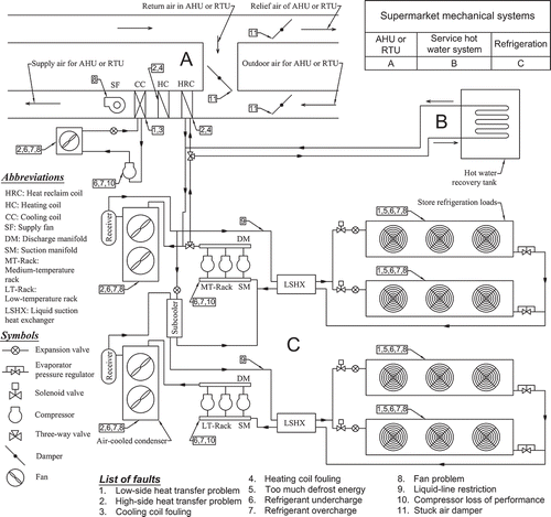
A schematic layout of supermarket equipment is depicted in . The refrigerant is compressed in compressors and passes through air-cooled condensers with several fans. After the condenser unit, the refrigerant passes through the drop-leg line toward the receiver. For low-temperature cabinets, the refrigerant is subcooled in a subcooler before passing through the expansion valves (ASHRAE Citation2015). While expansion valves control the circuit's mass flow rate, evaporator pressure regulators (EPRs) control evaporating temperature by maintaining a fixed evaporating pressure (ASHRAE Citation2015). While traditional valve types include mechanical thermostatic expansion valves (TXVs) and EPRs, new systems use electronic expansion valves (EEVs) and electronic evaporator pressure regulators (EEPRs). After extracting the refrigeration heat from evaporators, hence, suction superheat, the refrigerant is collected via the suction manifold to complete the closed cycle.
For condensers, in order to maintain a certain high level of condensing pressure (hence, temperature), several control strategies are used that are referred to as “low-ambient control” (Wirz Citation2009). This is necessary because the condensers operate in winter. One of the common control strategies for air-cooled condensers with several fans is to cycle the fans on and off. This is done based on pressure or temperature switches installed on the condenser unit. The pressure switch on the condenser cycles more fans on when the pressure rises above its high limit. Similarly, it cycles more fans off when the pressure falls lower than its low limit. A temperature switch cycles fan on and off based on the ambient temperature. Another control strategy is “condenser flooding.” In this method, a bypass pipe from the discharge line is connected to the receiver via a three-way valve. In low ambient temperatures, the bypass valve opens to increase the receiver pressure and reduce the refrigerant mass flow rate in the condenser. Furthermore, air-cooled condensers may use “split condenser” low-ambient control (Wirz Citation2009). In this method, a three-way valve isolates out a portion of the condenser in cold or low-load conditions. Therefore, refrigerant only rejects the heat in the rest of the unit, which causes the condensing pressure to remain higher. New systems may use a combination of these low-ambient controls for a single condenser unit. An energy efficient control approach for condenser units is floating condenser temperature control, which maintains a 10°F (5.55°C) temperature difference (TD) for low-temperature circuits, and 15°F (8.33°C) TD for medium-temperature systems (ASHRAE Citation2015).
The parallel compressor unit meets the refrigeration loads via different control strategies, depending on the type of compressors. A simple control approach is to cycle motors on and off. More accurate controls include the use of compressor unloaders for reciprocating compressors (Reindl Citation2013). To meet higher loads, an off compressor is cycled on, is assigned an unloader, and is increasingly loaded until it reaches full capacity, when the next compressor is started. For screw compressors, a continuous slide valve is used to modulate compressor capacity (Reindl Citation2013). The use of variable-speed compressors is another method to meet varying refrigeration loads (ASHRAE Citation2015).
Sub-system interactions
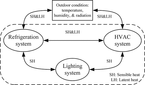
The performance of supermarket HVAC and refrigeration systems is affected by the external operating conditions, but there are also internal interactions between the systems because each removes sensible and latent heat from the store's interior (). An example of the interaction among subsystems is the case line layout of the refrigeration system, which can affect the total building's energy consumption up to 10% (Cole Citation2013). Also, with proper control, it's possible to reduce the refrigeration system's energy consumption by relying on the HVAC system to be the primary space dehumidifier, rather than having refrigeration systems remove occupied space humidity (Cole Citation2013).
Besides the load control interactions, integration of HVAC and refrigeration systems also plays an important role in minimizing supermarket operational costs. The use of heat reclaim coils has the potential to provide up to 100% of the space heating (Arias and Lundqvist Citation2006). The practice of using refrigerant heat recovery for service water heating is considered a baseline design feature in ASHRAE's (Citation2015) Advanced Energy Design Guide (AEDG) for grocery stores, rather than an energy-saving strategy.
HVAC and lighting systems are common among all commercial building types, not just supermarkets, so an AFDD method could be applied to these components regardless of the type of building. What makes a supermarket unique is, first, the refrigeration system, and second, the integration and interaction of subsystems. Therefore, the primary focus of the present article is on supermarket refrigeration AFDD.
AFDD fundamentals
AFDD methods for building mechanical systems typically function based on some identified performance indices or features sensitive to a specific fault. A significant deviation of a performance index from its predicted value or exceeding a pre-set threshold can be the indication of a fault.
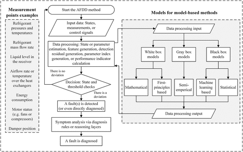
depicts a general information-flow architecture into which many AFDD algorithms can fit. Except expert systems, which use simple conditional statements, most methods require a model to process the input data for the predicted value. Therefore, one classification of these AFDD methods is to classify the model. Depending on the type of process, an AFDD method may use white, gray, or black box models to process the input data. White and gray box models require a priori knowledge of the system; black box models rely merely on historical data from the system.
According to one definition, an “unpermitted deviation of at least one characteristic property of the system” is a fault (Isermann Citation2011). In the proposed AFDD architecture in , the determination of the presence of a fault in a given system is referred to as detection. Fault diagnosis involves determination of the type and/or location. In some applications diagnosis includes time-varying behavior of a fault, but this is not common in AFDD for building mechanical systems. Fault evaluation or prognostics is an assessment of the severity of the fault. These definitions are consistent with Isermann (Citation1984) and Katipamula and Brambley (Citation2005). In AFDD for building mechanical systems, if diagnosis is provided, it typically comes after or concurrently with detection, and evaluation is often not included (Katipamula and Brambley Citation2005; Yuill and Braun Citation2016).
Supermarket equipment AFDD
Similar to other buildings, AFDD methods for supermarkets use one or several performance indices as sensitive features to faults at various implementation levels: whole-building, system, and component levels. At a whole-building level, the overall performance of a building is analyzed to detect potential faults (Datta et al. Citation1997; Mavromatidis et al. Citation2013). A system level AFDD addresses major energy consuming systems such as the HVAC, refrigeration, and lighting systems (Mavromatidis et al. Citation2013; Srinivasan et al. Citation2015). A component level AFDD method narrows down the root cause of a problem in a component such as display cases or cold rooms (O'Neill et al. Citation2014; Srinivasan et al. Citation2015; Thybo and Izadi-Zamanabadi Citation2004; Yang et al. Citation2011a, Citation2011b), compressors (Fisera and Stluka Citation2012; Keres et al. Citation2013), and the charge system (Assawamartbunlue and Brandemuehl Citation2006; Srinivasan et al. Citation2015; Taylor and Corne Citation2002).
One sensitive feature is energy or power consumption. Several AFDD methods used this as the main sensitive feature for AFDD (Fisera and Stluka Citation2012; Mavromatidis et al. Citation2013; Srinivasan et al. Citation2015). Others use control signals, system states, valve positions, and various measurement points from the air-side or refrigerant-side of the system (Porter et al. Citation2008; Thybo and Izadi-Zamanabadi Citation2004; Yang et al. Citation2011a, Citation2011b).
Supermarket refrigeration systems are more complex than typical air-conditioning systems. They contain more components, and control logic that is usually proprietary and unavailable to third parties. That makes it challenging for developers of model-based AFDD methods to create a forward model of the system based on white or gray box models. This has pushed many recent model-based supermarket refrigeration AFDD methods to be based on data-driven (black box) models. They predict the current system performance from the system's historical behavior (Assawamartbunlue and Brandemuehl Citation2006; Datta et al. Citation1997; Mavromatidis et al. Citation2013; Srinivasan et al. Citation2015; Taylor and Corne Citation2002).
In the following sub-sections, supermarket refrigeration AFDD is explored in detail and related AFDD methods are grouped and reviewed.
Energy analysis-based AFDD
Whole building AFDD can be used to identify overall energy consumption problems by comparing the current energy usage with historical energy data or standard baseline values. The advantage of whole building level methods is their ability to consider the overall energy performance of the system rather than focusing on faults in a specific component. A supermarket with fault-free components may still operate inefficiently and waste energy due to a poorly chosen control setting or design. These methods can detect changes in operation such as a set-point or control sequence change that increase the energy consumption, even if no physical component fault is present.
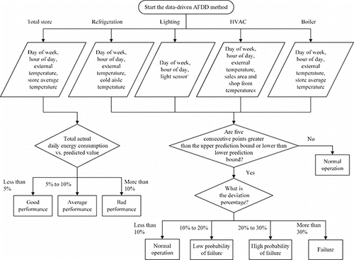
A recent whole building and system level AFDD was presented by Mavromatidis et al. (Citation2013). An expected energy consumption threshold for each hour of the day is calculated with a neural network model trained with historical data. Then the current value of the energy consumption is compared with those thresholds at the whole building and system levels ().In this two-level AFDD method, first, the total daily energy consumption is compared with the predicted values, and second, system-level energy consumptions are checked against the calculated confidence intervals. A flow chart of the AFDD algorithms by Mavromatidis et al. (Citation2013) is shown in .
Fig. 4. Data-driven AFDD method—First level of the detection on the left branch, and second level of the detection on the right branch.
With only energy meter data available at the system level, these methods can only detect the presence of a fault rather than diagnose the fault type or location. Additional sensor data is required to diagnose faults at the whole-building, system, or component levels.
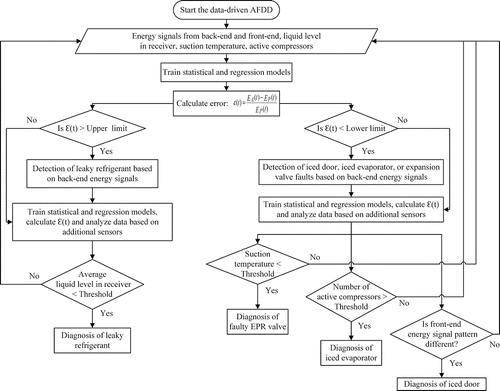
Srinivasan et al. (Citation2015) proposed an AFDD method to address system level fault detection, as well as component level fault diagnosis. It uses energy signals, as well as some additional sensor information, to detect four faults: charge leakage, expansion valve malfunction, iced-up evaporator, and iced display door. A fault is detected by monitoring energy signals, and diagnosed with the use of additional sensors. A seasonal autoregressive integrated moving average (SARIMA) statistical model coupled with a regression model was tested against a real supermarket chain's work-order logs. The hypothesis behind their methodology is that the presence of any fault in the system manifests itself in the energy signals. The SARIMA and regression models are trained with a 30-day set of normal (presumably fault-free) time-series data with 15-minute time intervals. This is a period for which no fault has been logged. Once a fault is flagged at time t, it should be taken out from the training dataset. The role of the regression model is to provide substitute training set parameter values while the actual parameter value returns to its normal operation. The detection rule flags a fault if the prediction error exceeds its upper or lower bounds. shows a flowchart description of the method by Srinivasan et al. (Citation2015).
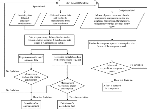
In another example, Fisera and Stluka (Citation2012) proposed a remote performance monitoring methodology for supermarket refrigeration systems that requires no more than typical sensors. The AFDD method addresses the detection of anomalous and degradation faults at the system level and rack compressor faults at the component level. The core algorithm uses regression models to predict energy consumption based on existing data logs. It creates a baseline energy consumption model to be compared with the current measured data. While the energy model for the anomaly detection algorithm uses recent historical data, the energy model for degradation fault uses the data from a well-separated period of data for training purposes (e.g., last season). Neither of these algorithms would have the ability to detect installation faults.
Component-level fault detection proposed by Fisera and Stluka (Citation2012) was applied on compressor racks. A compressor model was used to predict the power consumption based on the compressor sensor data (e.g., temperatures and pressures). With the actual power consumption known, the comparison of the compressor actual power consumption with the predicted value could reveal the existence of a fault in the compressor (). No information about the model itself was presented in Fisera and Stluka (Citation2012) article. shows a flow chart of the AFDD algorithm by Fisera and Stluka (Citation2012).
A similar work to the one presented by Fisera and Stluka (Citation2012) is described in Fisera and Hrncar (Citation2012).
Thermodynamic analysis
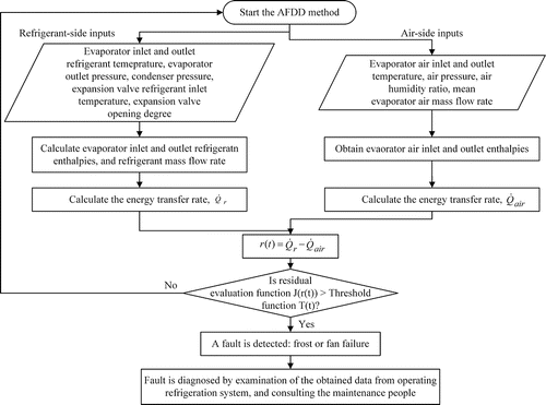
The presence of a fault can affect the thermodynamic behavior of the system in the form of a change in the temperature, pressure, air and mass flow rates, and heat transfer rates. Display cases are an important part of the supermarket refrigeration systems and are the second largest consumers of electricity in the refrigeration system after the compressor racks (DOE Citation2012). Thybo and Izadi-Zamanabadi (Citation2004) used energy balance equations for the evaporators to diagnose two particular faults. One was the reduced airflow rate caused by fan failure, and the other was icing-up (frost) of the evaporator. Simplified steady-state models of the refrigeration cabinet and the air-cooled evaporator heat transfer rates were uses to develop this AFDD method.
(1)
(2) where
and
are the calculated heat transfer rates of the evaporator from the refrigerant-side and airside, respectively. The refrigerant enthalpies, hi, r and ho, r, and air enthalpies, hi, air and ho, air were obtained with the use of the pressure and temperature sensors of the control system. The refrigerant mass flow rate was estimated from an expansion valve characteristic table. The airflow rate is the average constant airflow rate over the evaporator under normal operation.
The residual expression in Equation Equation3(3) was used for AFDD (Thybo and Izadi-Zamanabadi Citation2004):
(3)
In theory, because of the first law of thermodynamics, such residual calculation should not be able to reflect the presence of a fault. For instance, if the evaporator is fouled, the airflow rate and airside heat transfer rate reduce. This reduces the load on the coil, which causes the expansion valve to reduce the amount of the refrigerant flow to the coil, so the refrigerant-side heat transfer rate also is reduced. However, if one parameter in this residual calculation is fixed as the normal value, the refrigerant- and airside heat transfer rates differ during the occurrence of a fault. In this case, the normal parameter is the airflow over the evaporator, . A significant residual deflection in comparison to the normal operation indicates an existing fault. The detection of the fan fault and frost formation on the coil were shown with the use of time-series data products in the article by Thybo and Izadi-Zamanabadi (Citation2004). Although the fault could be detected in the algorithm proposed by Thybo and Izadi-Zamanabadi (Citation2004), fault diagnosis was not fully developed. The algorithm of the AFDD method by Thybo and Izadi-Zamanabadi (Citation2004) is depicted in .
A dynamic display case model was used in the AFDD method proposed by Yang et al. (Citation2011a). They developed two Kalman-filter-based methods (one KF method and one extended KF method (EKF) for detection and isolation of sensor faults and evaporator heat transfer faults. Two temperature sensors—air temperature, Tair, and evaporator tube surface temperature, Twall—with four types of problems were considered: sensor drift, sensor offset, sensor freeze, and sensor hard-over (the term “hard-over” implies an extreme frozen sensor value in this context). Besides the sensor faults, the evaporator's overall change in heat transfer coefficient due to an iced-up evaporator coil was tested. A dynamic display case model that includes evaporator and expansion valve sub-models was used from Larsen et al. (Citation2007). Equations Equation4(4) through Equation9
(9) describe the dynamic behavior of the heat transfer (Larsen et al. Citation2007).
(4)
(5)
(6)
(7)
(8)
(9)
is the heat transfer rate, M is the mass, Cp is the specific heat, T is the temperature, and
is the external heat load on the air curtain. Mr is the mass of the refrigerant in the evaporator that is calculated in Larsen et al. (Citation2007) based on the inlet valve position status (open or closed). A major limitation of such dynamic modeling is that it was assumed that the dynamic state of the goods (e.g., mass and Cp) as well as the
is available as known data. Furthermore, although fault detection was successful, neither of the KF methods could isolate the sensor faults from the evaporator heat transfer fault or vice versa. To tackle these drawbacks, Yang et al. (Citation2011b) developed the unknown-input-observer method in which the dynamic state of the goods as well as the
are unkown parameters. However, that method can only isolate the evaporator heat transfer fault. Finally, Yang et al. (Citation2011b) combined EKF and unknown-input-observer methods and found that this could successfully handle the detection and isolation of the faults.
Sensor-value threshold-based AFDD
A simple form of AFDD that checks a sensor value against a fixed and pre-set threshold has been used for many years in the direct digital controllers (DDCs) of building mechanical systems. Examples of that in supermarket equipment include display case alarms that are triggered when the case temperature rises above a limit, or compressor suction or discharge pressure and temperature sensor checks. Porter et al. (Citation2008) claim an invention in which for a heavily instrumented supermarket refrigeration system, the AFDD simply functions by comparing the sensor values against their pre-set thresholds. It monitors all of the major refrigeration system components as well as the additional devices that affect the operational states in a refrigeration circuit such as condenser receivers, subcoolers, liquid-suction heat exchangers, and defrost valves.
Although sometimes such methods provide good information about a system problem, they have some limitations. They annunciate fault symptoms rather than faults themselves. For instance, an abnormal rise in the case temperature is a problem, but it is unclear whether it is caused by the door being opened, by a broken evaporator fan motor, or some other operating conditions or faults. Further, because a fixed threshold is set for the sensor value ranges, it has to be wide enough to avoid false alarms, which reduces the accuracy of the method. Yuill et al. (Citation2014) evaluated such a method using the evaluation technique of Yuill and Braun (Citation2013), and found false alarm rates consistently over 95%.
AFDD based on alarm analysis
Large numbers of alarms are generated in a typical refrigeration system. For instance, if a cabinet temperature rises above a pre-defined value, a high-temperature alarm is raised. Taylor and colleagues (Citation2002) used alarm data from a central alarm monitoring center of 400 supermarkets to detect and predict refrigerant leakage in the system. Evolutionary algorithms and traditional backpropagation (BP) techniques were used to train neural network models. In order to distinguish refrigerant loss events among the alarm data, 240 records of visits to fix refrigerant leakage problem were obtained over a period of 2 years. A classifier was created to detect whether a refrigerant leak happens at the current operation of the system. Although this system did not provide a high level of prediction accuracy, the system could alert the staff of the possibility of an ongoing leakage.
In another use of alarm data, Taylor and Corne (Citation2002) developed an algorithm to predict the future alarm frequency in a supermarket. For a particular supermarket, data for a period of 672 days were analyzed to understand the weekly patterns (e.g., the busiest weekday in terms of the alarms), and to predict a total number of alarms for a specific weekday. Data, in the form of warnings, were grouped into: cabinet; cold-room; and plant (e.g., compressors and condensers) alarm records. Three prediction techniques—straightforward BP, evolving search and backpropagation (EB), and predictive rulesets—were used. In order to predict the total alarms on Mondays, for example, the previous 7 days were considered. The reported prediction accuracies range from about 58% to 78%. The EB training method prediction accuracy was slightly better than BP. Although the prediction results for busy days (Friday and Saturday) were fairly accurate, more accurate predictions are needed for real application of these techniques. This was attributed to the small amount of training data.
Adaptability of HVAC AFDD to supermarket refrigeration
With thelackof a comprehensive and successful AFDD method for supermarket equipment, an important question is whether HVAC AFDD methods can be adapted to supermarket applications. Various operational parameters from the high side and low side of a DX air-conditioning system with fixed orifice (FXO) valve (Breuker and Braun Citation1998; Rossi et al. Citation2006), TXV (Chen and Braun Citation2001; Li and Braun Citation2009), and EEV (Kim and Kim Citation2005) are used for AFDD purposes. These are analyzed below in terms of their adaptability to refrigeration systems. Supermarket display cases use TEVs or EEVs, so only diagnostic classifiers that are applicable to TXV and EEV equipped systems are shown in . These can be classified as sensor-value threshold-based AFDD methods. However, the operational parameters can be used in various AFDD methods. The arrows indicate whether the variable increases (↑), decreases (↓), does not change ( = ), or is not considered ( − ) when the fault is present.
Table 1. Fault characteristics of two AFDD protocols for unitary air-conditioning systems with TEV and EEV.
The sensitive features in the diagnostic classifier table have been investigated to determine if they can be used for supermarkets systems, or if there is a compelling reason to disqualify their applicability. For the purpose of this investigation, measurement data from four supermarket stores in the United States were obtained and used. The raw datasets included 15-minute time-series data from most of the important refrigerant-side temperature and pressure measurements. These data were collected on condition of anonymity for the stores. through 11 show portions of the data and some data products that can be used to determine whether existing AFDD methods could potentially be applied to refrigeration systems successfully.
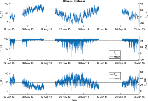
Fig. 8. Store 4 System A. Outdoor air temperature, condensing temperature, and condenser split over a 1-year period.
provides properties of 18 different refrigeration systems in these four stores.
Table 2. Refrigeration system properties.
A proposed feature for condenser fouling is the condensing temperature or difference between condensing temperature and ambient temperature (Tc − Tamb) or “condenser split.” The condenser split was calculated from Equation Equation10(10) .
(10) where Tcs is the condenser split, Tsat(Pdischarge) is the calculated condensing temperature, and Tamb is ambient temperature.
depicts a sample store outdoor air temperature, condensing and condenser split temperatures. The condensing temperature is controlled at a set-point (e.g., 95°F [35°C]) throughout the year. This causes the condenser split to vary significantly throughout the year. The raw datasets contained some periods of missing data, which are blank in and .
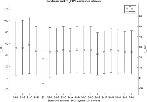
shows the 95% confidence intervals of the condenser split values for 18 different systems in four stores. They vary drastically between 0°F (0°C) to more than 100°F (56°C). Based on the previous analyses, it is concluded that condensing temperature and condenser split diagnostic features cannot be applied to supermarket air-cooled condensers without special consideration of the control strategies, such as low-ambient control.
Fig. 9. Ninety-five percent confidence intervals for condenser split for 18 different systems in four stores.
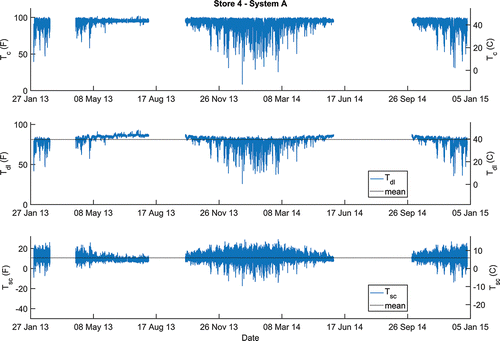
Subcooling in a typical Rooftop Unit (RTU) air-conditioning system is typically in the range of 10°F–20°F (6°C–12°C). A considerable change in the subcooling temperature can be an indication of a charge problem. However, in a commercial refrigeration system, the refrigerant pathway from the condenser outlet to the expansion valve experiences different conditions. Subcooling varies significantly depending on the location of the temperature measurements on the drop-leg pipe or liquid line. The drop-leg line is the connecting pipe between the condenser outlet and receiver inlet, and is a common temperature measurement for subcooling calculations. The subcooling values presented here are calculated by subtracting the condensing temperature from the drop-leg temperature.
(11)
In Equation Equation11(11) , Tsc is the subcooling temperature, Tsat(Pdischarge) is condensing temperature, and
is the drop-leg temperature.
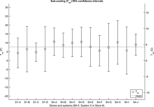
shows an example store's condensing temperature, drop-leg temperature, and subcooling amount measured over a 1-year period. shows the 95% confidence intervals of the subcooling values for 14 different systems in two stores. In the measurement data, the subcooling ranges from about −10°F (−6°C) to more than 30°F (17°C) when calculated with Equation Equation11(11) . In warmer seasons, the subcooling increases, and in colder seasons it decreases. Some of the systems show negative subcooling temperature, which is typically undefined (). The reason could be because of the hot gas bypass from the hot gas pipeline to the drop-leg pipe due to the condenser flooding control strategy. This allows the refrigerant in the drop-leg line to be at a higher temperature than the condensing temperature, which gives an apparent negative value for subcooling. In conclusion, subcooling cannot be used in the AFDD for such systems without a special consideration for low-ambient control strategies.
Fig. 10. Store 4 System A. Condensing temperature, drop-leg temperature, and sub-cooling for a 1-year period.
The evaporating temperature in supermarket equipment is controlled with the use of EPRs. These valves are installed downstream of the evaporators and open on the rise of the inlet pressure. EPRs are set to maintain a certain evaporator pressure. The combination of TXV and EPR ensures that the evaporator could respond to load variations while maintaining a constant evaporating temperature. Each different evaporator on the same suction manifold may have a different evaporating temperature from the others.
Although individual evaporating pressures and temperatures may be accessible from local display case controllers, they may not be available as logged data to trend in a normal supermarket equipment. Therefore, these features cannot be investigated without the availability of more sensor data. The only available suction pressure in our dataset is the main suction pressure of the suction manifold. The individual evaporating pressures are not available in the current dataset.
Concluding remarks
The AFDD literature was reviewed, and the relevant AFDD methods for supermarket application were collected and presented. Also, the adaptability of key performance indices in HVAC AFDD for application in supermarket refrigeration was investigated. The following conclusions and recommendations are made from the analyses:
| • | There are several existing AFDD methods for supermarket equipment at different levels, from whole building to component levels. | ||||||||||||||||||||||
| • | Supermarket AFDD is still in its early stages of development and there is a need to develop AFDD methods for supermarket refrigeration and AFDD methods that consider the interconnecting effects of the sub-systems on one another. | ||||||||||||||||||||||
| • | The authors recommend that new AFDD methods take advantage of the following sensor data in the refrigeration system, since many of them do not require adding sensors to the system:
| ||||||||||||||||||||||
| • | There is a need for additional data such as faulty data at known fault severity levels from refrigeration equipment to facilitate the development of supermarket-specific AFDD approaches. Without such data, it is very difficult for developers of AFDD to develop or test new methods for supermarket equipment. | ||||||||||||||||||||||
| • | The complexity of the supermarket refrigeration due to their size and the use of extra components, such as liquid-suction heat exchangers, subcoolers, receivers, pressure regulators, the existence of the secondary refrigeration circuit, and proprietary control logic makes it difficult to create a physics based model of the system for AFDD purposes. Most AFDD methods in the literature are based on data-driven models. | ||||||||||||||||||||||
| • | The performance indices used in the existing HVAC AFDD methods are not readily adaptable for supermarket refrigeration due to the use of control strategies such as low-ambient control and differences in the physical configurations of the systems. | ||||||||||||||||||||||
Nomenclature
| A | = | = area |
| C | = | = heat capacity |
| E | = | = energy consumption |
| EKF | = | = extended Kalman filter |
| h | = | = enthalpy |
| J | = | = residual evaluation function |
| KF | = | = Kalman filter |
| LH | = | = latent heat |
| = | = mass flow rate | |
| M | = | = mass |
| P | = | = pressure |
| = | = heat transfer rate | |
| r | = | = residual |
| SH | = | = sensible heat |
| t | = | = time |
| T | = | = temperature |
| U | = | = heat transfer coefficient |
| UA | = | = heat transfer conductance |
Greek
| ϵ | = | = error |
Subscripts
| air | = | = air |
| A | = | = actual |
| airload | = | = airload |
| amb | = | = ambient |
| c | = | = condensing |
| cs | = | = condenser split |
| discharge | = | = discharge |
| drop_leg | = | = drop-leg pipe that connects the condenser to the receiver |
| e | = | = evaporating |
| goods | = | = goods |
| i | = | = inlet |
| = | = mass flow rate | |
| o | = | = outlet |
| P | = | = predicted |
| r | = | = refrigerant |
| ra | = | = return air |
| sat | = | = saturation |
| sc | = | = subcooling |
| wall | = | = wall |
Funding
The research work is supported by ASHRAE 1615 RP, sponsored by TC 7.5 Smart Building Systems, and TC 10.07 Commercial Food and Beverage Refrigeration Equipment. The authors are thankful to ASHRAE for funding this project.
References
- Arias, J., and P. Lundqvist. 2006. Heat recovery and floating condensing in supermarkets. Energy and Buildings 38(2):73–81.
- ASHRAE. 2015. Advanced energy design guide for grocery stores—Achieving 50% energy savings toward a net zero energy building. Atlanta: ASHRAE.
- Assawamartbunlue, K., and M.J. Brandemuehl. 2006. Refrigerant leakage detection and diagnosis for a distributed refrigeration system. HVAC&R Research 12(3):389–405.
- Bahman, A., L. Rosario, and M.M. Rahman. 2012. Analysis of energy savings in a supermarket refrigeration/HVAC system. Applied Energy 98:11–21.
- Brambley, M.R., D. Hansen, P. Haves, D.R. Holmberg, S.C. McDonald, K.W. Roth, and P. Torcellini. 2005. Advanced sensors and controls for building applications: Market assessment and potential R&D pathways. Report PNNL-15149. Pacific Northwest National Laboratory, Washington, DC, USA.
- Breuker, M.S., and J.E. Braun. 1998. Common faults and their impacts for rooftop air conditioners. HVAC&R Research 4(3):303–18.
- CBECS. 2006. Table C3A. Consumption and Gross Energy Intensity for Sum of Major Fuels for All Buildings. Forms EIA-871A, C, and E of the 2003 Commercial. Washington, DC: Energy Information Administration, Office of Energy Markets and End Use.
- Chen, B., and J.E. Braun. 2001. Simple rule-based methods for fault detection and diagnostics applied to packaged air conditioners. ASHRAE Transactions 107:847–57.
- Cole, P. 2013. Balancing latent heat load between display cases and store comfort cooling. Report ASHRAE 1467-RP. ASHRAE.
- Datta, D., S. A. Tassou, and D. Marriott. 1997. Application of neural networks for the prediction of the energy consumption in a supermarket. Proceedings of the International Conference CLIMA 2000, 29 August to 2 September, 1997, Brussels, Belgium, 98–107.
- DOE. 2012. 2011 Building Energy Data Book. Washington, DC: United States Department of Energy.
- Dong, B., M. Gorbounov, S. Yuan, T. Wu, A. Srivastav, T. Bailey, and Z. O'Neill. 2013. Integrated energy performance modeling for a retail store building. Building Simulation—Tsinghua University Press 6(3):283–95.
- EnergyStar. 2008. Energy Star building manual-Facility Type: Supermarkets and Grocery Stores. Washington, DC: United States Environmental Protection Agency.
- Fisera, R., and M. Hrncar. 2012. System and method for performance monitoring of commercial refrigeration. U.S. Patent Application 12/976,088.
- Fisera, R., and P. Stluka. 2012. Performance monitoring of the refrigeration system with minimum set of sensors. World Academy of Science, Engineering and Technology 6(7):396–401.
- FMI. 2013. Grocery Store Chains Net Profit—Percent of Sales. Arlington, VA: Food Marketing Institute.
- Ge, Y.T., and S.A. Tassou. 2011. Performance evaluation and optimal design of supermarket refrigeration systems with supermarket model “SuperSim.” Part II: Model applications. International Journal of Refrigeration 34(2):540–9.
- Hamlett, J., A. Alexander, A. Bailey, and G. Shaw. 2008. Regulating UK supermarkets: An oral-history perspective. History & Policy. http://www.historyandpolicy.org/policy-papers/papers/regulating-uk-supermarkets-an-oral-history-perspective
- Isermann, R. 1984. Process fault detection based on modeling and estimation methods—A survey. Automatica 20(4):387–404.
- Isermann, R. 2011. Fault-diagnosis applications: Model-based condition monitoring: Actuators, drives, machinery, plants, sensors, and fault-tolerant systems. London: Springer.
- Katipamula, S., and M.R. Brambley. 2005. Review article: Methods for fault detection, diagnostics, and prognostics for building systems—A review. HVAC&R Research 11:3–25.
- Keres, S.L., A.D. Litch, and A.R. Gomes. 2013. Fault detection and diagnosis for refrigerator from compressor sensor. U.S. Patent Application No. 13/531, 707.
- Kim, M., and M.S. Kim. 2005. Performance investigation of a variable speed vapor compression system for fault detection and diagnosis. International Journal of Refrigeration 28(4):481–8.
- Larsen, L.F., R. Izadi-Zamanabadi, and R. Wisniewski. 2007. Supermarket refrigeration system-benchmark for hybrid system control. Proceedings of the European Control Conference, July 2-5, 2007, Kos, Greece, pp. 113–20.
- Li, H., and J. Braun. 2009. Development, evaluation, and demonstration of a virtual refrigerant charge sensor. HVAC&R Research 15(1):117–36.
- Mavromatidis, G., S. Acha, and N. Shah. 2013. Diagnostic tools of energy performance for supermarkets using artificial neural network algorithms. Energy and Buildings 62:304–14.
- O'Neill, Z., M. Shashanka, P. Haves, and T. Bailey. 2014. Model-based real-time whole building energy performance monitoring and diagnostics. Journal of Building Performance Simulation 7(2):83–99.
- Porter, M.R., J.J. Rozsnaki, and O. Ahmed. 2008. Refrigeration system fault detection and diagnosis using distributed microsystems. U.S. Patent Application No. 11/786,033.
- Reindl, D.T. 2013. Sequencing and control of compressors. ASHRAE Journal 55(11):14–29.
- Rossi, T.M., D. Rossi, J.D. Douglas, and T.P. Stockman. 2006. Apparatus and method for detecting faults and providing diagnostics in vapor compression cycle equipment. U.S. Patent No. 6,658,373.
- Srinivasan, S., A. Vasan, V. Sarangan, and A. Sivasubramaniam. 2015. Bugs in the freezer: Detecting faults in supermarket refrigeration systems using energy signals. Proceedings of the 2015 ACM Sixth International Conference on Future Energy Systems, July 14-17, Bangalore, India, pp. 101–10.
- Taylor, D., and D. Corne. 2002. Refrigerant leak prediction in supermarkets using evolved neural networks. Proceedings of the 4th Asia Pacific Conference on Simulated Evolution and Learning (SEAL), November 18-22, 2002, Orchid Country Club, Singapore.
- Taylor, D.W., D.W. Corne, D.L. Taylor, and J. Harkness. 2002. Predicting alarms in supermarket refrigeration systems using evolved neural networks and evolved rulesets. Congress on Evolutionary Computation, May 12-17, 2002, Honolulu, HI, 1988–1993.
- Thybo, C., and R. Izadi-Zamanabadi. 2004. Development of fault detection and diagnosis schemes for industrial refrigeration systems-Lessons learned. Control Applications, 2004. Proceedings of the 2004 IEEE International Conference, September 2-4, Taipei, Taiwan, 2:1248–53.
- Walker, D.H., and C. Awarded. 2001. Development and demonstration of an advanced supermarket refrigeration/HVAC system. Report ORL-970163, Oak Ridge, TN: Oak Ridge National Laboratory.
- Wichman, A., and J. Braun. 2009. Fault detection and diagnostics for commercial coolers and freezers. HVAC&R Research 15(1):77–99.
- Wirz, D. 2009. Commercial Refrigeration: For Air Conditioning Technicians. Clifton Park, NY: Delmar, Cengage Learning.
- Yang, Z., K. Rasmussen, A. Kieu, and R. Izadi-Zamanabadi. 2011b. Fault detection and isolation for a supermarket refrigeration system—Part two: Unknown-input-observer method and its extension. IFAC Proceedings Volumes 44(1):4238–43.
- Yang, Z., K.B. Rasmussen, A.T. Kieu, and R. Izadi-Zamanabadi. 2011a. Fault detection and isolation for a supermarket refrigeration system-part one: Kalman-filter-based methods. IFAC Proceedings Volumes 44(1):13233–8.
- Yuill, D.P., and J.E. Braun. 2013. Evaluating the performance of fault detection and diagnostics protocols applied to air-cooled unitary air-conditioning equipment. HVAC&R Research 19(7):882–91.
- Yuill, D.P., and J.E. Braun. 2016. Effect of the distribution of faults and operating conditions on AFDD performance evaluations. Applied Thermal Engineering 106:1329–36.
- Yuill, D.P., H. Cheung, and J.E. Braun. 2014. Validation of a fault-modeling equipped vapor compression system model using a fault detection and diagnostics evaluation tool. International Refrigeration and Air Conditioning Conference, July 14-17, 2014, West Lafayette, IN, 15:1–10.

