Abstract
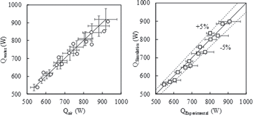
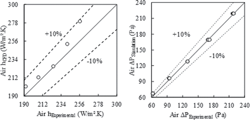
The airside thermal resistance of air-to-fluid heat exchangers dominates the overall thermal resistance. On conventional heat exchanger's, fins are required to address such challenges; but their benefits are not limitless and are bound mainly by the tube size and shape. The reduction of the tube characteristic length has favorable impact on compactness and heat transfer. Conventional tubes are typically limited to round, elliptical or flat shapes which result in particular thermal-hydraulic characteristics. The current article has three main objectives. First, discuss the importance of fins on typical air-to-fluid heat exchanger's and how they become unattractive at smaller characteristic lengths with numerical analyses to support this argument from different perspectives. Second, present a proof-of-concept design with small finless tubes and a novel shape that can outperform a microchannel heat exchanger. Third, present a comprehensive analysis with shape optimization leveraging automated computational fluid dynamics simulations and approximation assisted optimization techniques. Optimum designs can achieve more than 50% reduction in size, material, and pressure drop compared to the baseline microchannel heat exchanger. The method is validated with the experimental validation of a metal three-dimensional printed prototype of the NTHX-001. The numerical simulations agreed within less than 5% in capacity, 10% in air heat transfer coefficient, and 15% in air pressure drop.
Introduction
Compact heat exchangers (HXs; Dh < 6.0 mm [Shah and Sekulic Citation2003]) with high-performance (Jacobi and Shah Citation1998; Kays Citation1960; Kays and London Citation1984; Webb and Kim Citation2005) surfaces is a very common; however, broad topic that draws interests from all engineering applications. Most technologies contain at least one HX serving as a fundamental component for proper system functioning. The rapid population growth, demand for energy resources, environmental concerns, space race and economy are all good motivators for developing smaller, lighter, and more efficient HX's.
The typical solution for compactness and thermal resistance reduction is using extended secondary heat transfer surfaces (fins) which, in spite the obvious benefits, bring many drawbacks. Fins will naturally provide additional viscous resistance and have a lower heat transfer potential due to temperature gradient. Furthermore, on the gas side, fins reduce mixing; and the actual heat transfer coefficient on fins is smaller than the tubes. The resulting overall heat transfer coefficient can be as low as 40% (Webb and Kim Citation2005) less than finless surfaces. Such impact on the thermal resistance is compensated by the additional surface area the fins provide. Fins are also susceptible to performance degradation under fouling or frosting conditions, in particular for enhanced surface fins (Huang et al. Citation2014a). Finally, fins inevitably result in more material, and thus potentially heavier HX's and higher manufacturing costs. The reason fins are necessary is that typically the primary surfacescannot alone provide the required thermal resistance. Consequently, fin enhancement is a much more attractive research area compared to tube enhancement.
Fins are generally enhanced using discontinuous surfaces such as louvers (Atkinson et al. Citation1998; Cowell et al. Citation1995; DeJong and Jacobi Citation2003; Hsieh and Jang Citation2006; Kim and Bullard Citation2002; Leu et al. Citation2001; Perrotin and Clodic Citation2004; Tafti et al. Citation2000; T'Joen et al. Citation2011; Wang et al. Citation1998; Yun and Lee Citation1999), slits (Jacobi and Shah Citation1998; Kays Citation1960; Li et al. Citation2011; Tao et al. Citation2007; Yun and Lee Citation1999, Citation2000), and perforated fins (Fujii et al. Citation1988; Jacobi and Shah Citation1998; Kays Citation1960; Liu et al. Citation2016). The last differs from the other two on two matters. On one hand, it has reduced surface area due to material removal from perforation; while on the other hand, there are less stagnation points, resulting in reduced friction resistance (Kays Citation1960). Wavy fins (Kays Citation1960; Kays and London Citation1984; Lotfi et al. Citation2014; Wang et al. Citation1999) are not a discontinuous surface, but they provide additional surface area for the same volume and can promote chaotic flow (Mohammed et al. Citation2011; Sui et al. Citation2010), which result in enhanced heat transfer and are preferred in some applications (Huang et al. Citation2014a; Silva et al. Citation2011). Recent efforts on fin enhancement are winglets, or vortex generators (Arora et al. Citation2016; Gholami et al. Citation2014; Huisseune et al. Citation2013; Jacobi and Shah Citation1995, Citation1998; Lotfi et al. Citation2014; Salviano et al. Citation2016; Tiwari et al. Citation2003) which result in induced turbulence within the boundary layer, or even its disruption, thus enhancing the thermal performance.
From a primary surface (tube) perspective, heat transfer coefficients inversely proportional to diameter (Bacellar et al. Citation2014a; Bacellar et al. Citation2014b; Chen et al. Citation2016; Kasagi et al. Citation2003; Paitoonsurikarn et al. Citation2000; Saji et al. Citation2001), thus having very high values in particular for diameters below 1.0 mm. A major shortcoming of round tubes, however, is the friction resistance, which is also inversely proportional to the diameter. HX's with such tube dimensions have larger face area (Bacellar et al. Citation2014b), which is a consequence of reducing frontal velocity and thus the pressure drop.
The limitation on friction resistance for round tubes can be addressed by employing alternate shapes. Min and Webb (Citation2004) studied tube shapes (round, oval, and flat) with tube diameters above 6.0 mm. They showed that flat and oval could have as low as 50% of the pressure drop compared to round tube, while reducing thermal performance by 10%–20%. Other relevant studies on alternate tube shapes in crossflow include polymer tubes with three different teardrop shapes (Li et al. Citation2004) and cam-shaped tubes (Lavasani et al. Citation2014; Nouri-Borujerdi and Lavasani Citation2007; Zhang et al. Citation2014). Others have combined these alternate tubes with enhanced fins (Joardar and Jacobi Citation2005; Leu et al. Citation2001; Lotfi et al. Citation2014; Tiwari et al. Citation2003). Flat, multi-port tube HX's, or microchannel HX's (MCHX; Kandlikar Citation2007, Citation2010; Tuckerman and Pease Citation1981) are currently the state-of-the-art in performance and compactness. Huang et al. (Citation2014b) developed a variable geometry MCHX design approach to address flow mal-distributions while optimizing material usage and localized thermal-hydraulic performance. Another significant branch of research is the shape optimization, which has many applications in various engineering problems most commonly applied to wings and airfoils (Hajek Citation2007; Sobieczky Citation1998). High-performing aerodynamic airfoil profiles have been studied on gas-engines (Onishi et al. Citation2014) and intercooled gas turbines (Ito et al. Citation2014). Other shape optimization studies include convective periodic channels (Cavazzuti and Corticelli Citation2008; Foli et al. Citation2006; Nobile et al. Citation2006; Stalio and Piller Citation2006), internally enhanced tubes (Duplain and Baliga Citation2009; Fabbri Citation1997, Citation1998; Lee and Lee Citation2013) and, most relevant to this work, the periodic crossflow over a tube bundle (Hilbert et al. Citation2006; Ranut et al. Citation2014).
This work argues that conventional air-to-fluid HX's design concepts and agreed upon practices to improve performance are limited and should be re-thought and renovated in line with modern modeling and manufacturing capabilities. That argument is addressed by three main objectives. First, discuss the importance of fins on typical air-to-fluid HX's and how they become unattractive at smaller characteristic lengths; and further present numerical analyses to support such statement from different perspectives. Second, present a proof-of-concept design with small finless tubes with a novel shape that can outperform a MCHX, followed by experimental validation of a metal three-dimensional (3D) printed prototype. Third, present a comprehensive analysis and shape optimization approach in order to explore the potential improvements to the proof-of-concept HX, leveraging automated computational fluid dynamics (CFD) simulations and approximation assisted optimization (AAO) techniques.
Airside modeling
CFD modeling and simulation
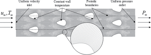
The stream-wise periodic flow numerical method for crossflow HX's proposed by (Patankar Citation1980) aims at reducing the computational cost by adequately reducing the computational domain without losing physical meaning. Typically, the end-effects can be neglected, and the thermal-hydraulic characteristics of a surface can be determined by a segment of the HX where the lower, upper, and longitudinal boundaries are assumed periodic or symmetric. In the literature, the numerical analysis on finless surfaces commonly employ two-dimensional computational domains (Bacellar et al. Citation2014b; Hilbert et al. Citation2006; Min and Webb Citation2004; Paitoonsurikarn et al. Citation2000; Ranut et al. Citation2014), which makes the simulations much lighter while still providing very reliable results.
Both thermal diffusion and viscous resistance within the boundary layer are function of the temperature and velocity gradient at the surface (Equations Equation1(1) and Equation2
(2) ) and require a much finer mesh near the wall in order to better capture the physics. Many CFD studies have no refinement near the tube wall (Hilbert et al. Citation2006; Ranut et al. Citation2014). It is considered a two-dimensional computational domain () with pave meshing scheme as well; however, the near wall region mesh is a fine map scheme with growing layers at a ratio of at most1.2.
(1)
(2)
Flow regime models are a very debatable issue, in particular for smaller diameter tubes when laminar flow model is typically used. This assumption may result in poor eddy flows prediction intrinsic to the flow separation given the nature of the flow across tubes. Although turbulence models are known to over predict heat transfer and friction for truly laminar flows, they can better solve a broader range of problems. This is preferable when one must simulate a large number of samples using common CFD settings. There are many turbulence models available in commercial CFD packages. The two-equation k-ϵ realizable (RKE; Shih and Zhu Citation1994) has proven to be a very robust model. The RKE ensures the solution obeys the non-negativity of turbulent normal stress (Schumann Citation1977), thus solutions are realistic (when converged) from the physical viewpoint. Additionally, the authors have observed a higher rate of convergence—i.e., fewer simulations fail or diverge solution—when using RKE for a large number of CFD simulations compared to other models, including laminar.
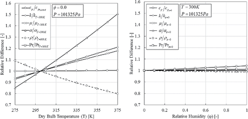
The thermophysical properties also have an impact on the outcomes of CFD simulations. In many heat transfer applications authors simplify the problem by using constant properties (Hilbert et al. Citation2006; Ranut et al. Citation2014). The temperature, however, may have a significant impact particularly on density, conductivity, and viscosity (). The constant properties may result in under-prediction, primarily of flow acceleration and thermal diffusion. One may argue that relative humidity would have also an impact on the thermophysical properties. The purpose of the CFD simulations is to evaluate the surface thermal-hydraulic performance and not the HX performance. In other words, the relevant properties would be conductivity (heat transfer coefficient—Equation Equation1(1) ), viscosity (friction—Equation Equation2
(2) ) and both momentum and thermal diffusivities (Prandtl number). The above properties, for a constant temperature, vary less than 0.5% when changing relative humidity (). For this reason, this study assumes dry air and uses ideal-gas model for density, whereas the other thermophysical properties are estimated with polynomial curve fits as function of temperature.
Finally, the simulation convergence criteria are set to a maximum residual of 10−5 for momentum and continuity, 10−6 for energy, and 10−3 (default) for turbulence. If the simulation does not meet the criteria, however, it stabilizes into a solution, it is assumed that if the standard deviation of the last 100 iterations is less than 0.5% of the average of those same 100 iterations, then it is converged.
CFD simulation data reduction
In this type of problem, it is convenient to define uniform wall temperature (), allowing one to easily calculate the heat transfer coefficient from the UA-Logarithmic Mean Temperature Difference method (Equations Equation3(3) and Equation4
(4) ).
(3)
(4)
For the pressure drop it is convenient to set the outlet boundary at uniform atmospheric pressure (0.0 gauge). Additionally, the dynamic pressure difference between inlet and outlet can be assumed insignificant compared to the static pressure difference. Finally, the buoyance term is also negligible for gases, therefore, the pressure drop is simply retrieved according toEquation Equation5(5) .
(5)
CFD grid uncertainty analysis
One standard approach to evaluating the CFD model uncertainty is the 5-step Grid Convergence Index (GCI; Equation Equation6(6) ) method (ASME Citation2009; Roach Citation1997; Roy and Oberkampf Citation2011), which quantifies the uncertainty of a metric of interest (ϕ) associated with the grid resolution for at least three mesh sizes. The procedure is simplified when using constant refinement ratio (r) since it eliminates the iterative calculations (Roy and Oberkampf Citation2011). Additionally, when the observed order of accuracy (p*) deviates in more than 10% from the formal (p) spatial discretization order of accuracy, then the effective value (p**) must be bounded by a minimum of 0.5 and the formal value (Oberkampf and Roy Citation2010). Moreover, if the last is the case, then the factor of safety (Fs) must be set to 3.0 (Roach Citation1997), otherwise a value of 1.25 (Roach Citation1997) is acceptable.
(6)
Tube shape parameterization
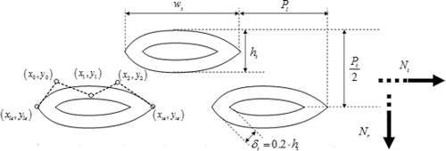
Nonuniform Rational B-Splines (NURBS; Tiller Citation1995) are very common in shape optimization problems (Cavazzuti and Corticelli Citation2008; Foli et al. Citation2006; Hilbert et al. Citation2006; Nobile et al. Citation2006; Ranut et al. Citation2014). In the present study, the authors consider a fourth-order NURBS curve (Equation Equation7(7) ) where the coordinates of the control points are normalized between 0 and 1. The leading edge (le) and trailing edge (te) points are fixed to (0,0) and (1,0), and the three mid-points are the shape design variables. The x-coordinate of the mid control points are bound by equally spaced slices in order to avoid self-intersecting curves ().
(7)
First- and second-order analyses
As previously stated, for conventional tube sizes, fins are an undesired necessity since they provide sufficient surface area to achieve the required thermal performance. However, first- and second-order analyses can show that while moving toward smaller diameters, the contribution from fins seem to have a limit.
The following analyses are undertaken assuming, for all surfaces: round tubes, flat fins, same refrigerant side cross-section area, constant tube pitch ratios, constant diameter-to-thickness ratio, constant number of tube banks, constant airflow rate, and velocities. Additionally, all results in the second-order analysis are based on numerical simulations using the airside modeling approach described in the previous section.
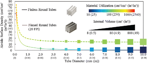
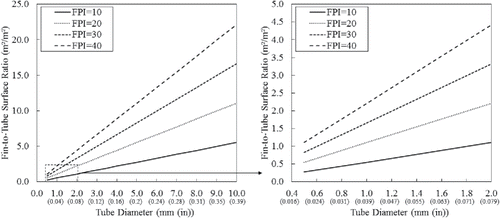
shows on the y-axis the compactness (surface-to-volume ratio), which regardless the surface type is inversely proportional to the tube diameter. Additionally, the compactness of finned tubes is approximately 20 times higher than finless tubes for larger diameters; however, the difference is reduced to 1 to 2 times at smaller diameters. At smaller tube diameters, the surface area contribution (Equations Equation8–10) reduces proportionally (), thus affecting the compactness as well. On the contour plot shows material utilization (surface-to-material volume ratio), which has the same trend as compactness, which means for smaller tubes there is an opportunity for reducing the amount of material. Last, but not the least, the symbol size in shows the internal volume as a function of diameter and behaves the same way as the previous metrics. The reduction of internal volume translates into less refrigerant charge which will consequently reduce the weight and potential environmental impact when using working fluids with global warming potential (GWP).
(8)
(9)
(10)
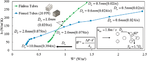
The reduction of the tube size has, most importantly, a significant impact on heat transfer coefficient (h). The relation between Nusselt and Reynolds numbers shows that as the characteristic length is reduced, the heat transfer coefficient is increased (Paitoonsurikarn et al. Citation2000; Equation Equation11(11) ). The most remarkable plots of these analyses are presented in , where it shows what is the cost (flow resistance—Equation Equation12
(12) ) of improving h when reducing tube diameter for both finned and finless tube surfaces. What these plots suggest is that there is a trade-off where at a certain diameter the finless tube surfaces achieve higher heat transfer coefficients at a lower cost compare to their finned counterparts. This finding reveals that adding (conventional) fins is not unconditionally needed; thus, fundamentally changing theHX designapproach.
(11)
(12)
Numerical investigation on standalone tube size and shape
This section demonstrates, based on numerical solutions, how the temperature and velocity gradient at the tube surface behave and consequently affect the thermal-hydraulic performance. The study comprises of parameterizing five tube hydraulic diameters, and five shapes (), both under same Reynolds number () and same frontal velocity (), respectively.
Fig. 7. Tube shapes: a. Round; b. Ellipse; c. Eye; d. Airfoil leading edge; e. Airfoil trailing edge.

Fig. 8. Local thermal-hydraulic characteristics for round tube at constant Reynolds: a. hydraulic boundary layer; b. temperature gradient at the wall; c. tangential velocity gradient at the wall.

Fig. 9. Local thermal-hydraulic characteristics for round tube at constant velocity: a. hydraulic boundary layer; b. temperature gradient at the wall; c. tangential velocity gradient at the wall.

The tube size analyses ( and ) show that, regardless whether the flows are dynamically equivalent or not, the thermal-hydraulic characteristics have the same trend with respect to the tube size. The intensity to which they change will be a function of the flow regime.
The following analysis () comprises investigating the different shapes' performance under a wide range of Reynolds numbers with fixed hydraulic diameter. The blunt shapes (round and ellipse) have better thermal performances (j-factor) but at a higher cost in friction (f-factor). The nonsymmetric (transverse axis) shapes (airfoil leading edge and airfoil trailing edge), though alone have lower thermal performance (j-factor), they have higher thermal-hydraulic ratio (j/f). Such characteristics are leveraged further in this manuscript.
Design problem formulation
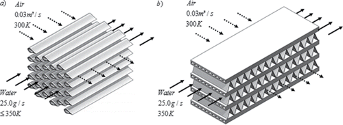
In the present study, the aim was to design a 1.0 kW air-to-water HX, for which a state-of-the-art MCHX (Private communications Citation2010) is used as a baseline ().
Proof-of-concept NTHX-001
A proof-of-concept(NTHX-001) was designed to deliver similar capacity as the baseline MCHX () while reducing the envelope volume by 20%, reducing the airside pressure drop by approximately 20%, maintaining the same approach temperature (50 K) and maintaining similar face area. The objective was to find a finless design that could leverage the small diameter and high-performing shapes to achieve the previously listed improvements.
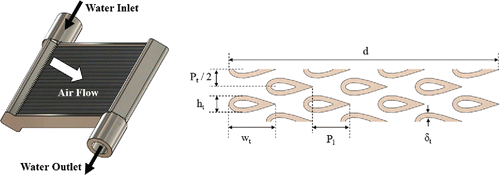
The tube shape is a version of the airfoil leading edge surface with minor adjustments to the NURBS control point coordinates. The available manufacturing option imposed a few design constraints to the wall thickness, tube height, and tube width. Several CFD simulations () were carried out on a trial and error basis with educated design parameters in order to find a potential candidate with sufficiently low thermal resistance while reducing the pressure drop of ∼20% (). The GCI for this CFD model is 0.1% for heat transfer and 0.397% for pressure drop.
The HX simulation including both fluids were performed within the CoilDesigner (Jiang et al. Citation2006) environment, an in-house code created to model any type of crossflow air-to-fluid HX. The CFD results were used to determine the airside performance, whereas the waterside was handled with existing correlations (Churchill Citation1977; Dittus and Boelter Citation1985; Gnielinski Citation1976) available in the literature for the equivalent inner hydraulic diameter for round channels. To account for differences in area and perimeter of the inner shape, the pressure drop on the waterside needs correction (ζ) according to Equations Equation13(13) and Equation14
(14) . The HX analysis and comparison results against the MCHX are shown in .
(13)
(14)
Table 1. NTHX-001 Numerical results compared to the baseline MCHX.
Analysis and shape optimization
Numerical optimization of HX's has been increasingly present in the literature with the rapid evolution of computational power and numerical methods. Heuristic optimization, such as genetic algorithms (GAs; Deb Citation2001), are a very popular optimization tool since they are more robust and overall less computationally expensive than traditional ones and can result in better designs (Gosselin et al. Citation2009; Huang et al. Citation2015).
Many studies are leveraging thecomputational power to couple numerical solvers such as CFD to GA's (Fabbri Citation1997; Foli et al. Citation2006; Nobile et al. Citation2006; Queipo et al. Citation1994) in order to investigate an otherwise impossible variety of new concepts. The cost of coupling, however, can be extremely high depending on the level of complexity of the geometry. More recently, some researchers have employed approximation techniques (Abdelaziz et al. Citation2010; Hilbert et al. Citation2006; Ranut et al. Citation2014) which reduce the number of numerical simulations required, thus saving a significant amount of computational time. Among these techniques is metamodeling, for example, a simplified version of an actual physical model, such as CFD, with reasonable prediction accuracy.
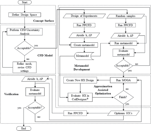
Abdelaziz and colleagues (Citation2010) introduced a highly cost-effective multi-scale analysis and optimization method for novel air-to-refrigerant HX's, which the framework () foundations are used in this work. Their method consisted of an AAO using parallel parameterized CFD (PPCFD; Abdelaziz et al. Citation2010), Kriging metamodeling (Cressie Citation1993) and multi-objective GA (MOGA). PPCFD () is an approach that automates the CFD simulations and allows for shape and topology change at run-time, which saves significant engineering time. The entire CFD modeling and simulation happen within ANSYS® platform, where geometry and meshing are built in Gambit 2.4.6 (ANSYS Citationn.d.) and the simulations are performed in Fluent 14.5 (ANSYS Citation2014). All other input/output and processed data occur within an external C# code tailored for the specific problem.
The optimizer in this framework evaluates the HX's within CoilDesigner® (Jiang et al. Citation2006) using the metamodels to calculate the airside thermal-hydraulic characteristics while using built-in correlations to evaluate the waterside with the appropriate correction factors. The optimization outputs contain all the HX models evaluated and a file containing the Pareto set (all designs that best satisfy the optimization objectives within the feasible domain; i.e., where all constraints are satisfied). For completeness, the designs in the Pareto set need to be simulated in CFD in order to verify the metamodel prediction accuracy.
Concept surface
This section entails the optimization a finless tube bundle with novel shapes, in staggered arrangement, as illustrated in . The optimization problem has four types of design variables (): “scaling variables,” which quantify absolute dimensions; “topology variables” quantifying relative dimensions independent of shape and size; “shape variables,” which in this work are the Cartesian coordinates of the three control points; and “fluid variables,” i.e., any quantity related to the flow operating conditions or physical state of the fluid.
Table 2. Design space.
The waterside tube shape is a function of the constant wall thickness. Preliminary structural analysis showed that a wall thickness equivalent to 20% of the tube height () is a safe assumption to ensure neither deformation nor mechanical collapse for an internal pressure at most of 6.0 MPa (NTHX-001 is 30%). Additionally, it was introduced the inlet approach temperature as a variable in order to achieve higher effectiveness since heat capacity is limited to a short range and the capacitance rates are fixed. A simple energy balance showed that reducing the inlet approach temperature up to 20% (40 K) of the baseline (50 K) ensures no Second Law violations thatcould undermine the numerical optimization.
CFD model
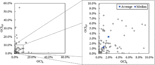
Bacellar and colleagues (Citation2015) have proposed a general way of estimating the CFD model uncertainty of the entire design space by employing the GCI method to all combinations of lower and upper bounds. The premise is that those designs have the most skewed computational domains, thus having a higher potential for poorer mesh elements and thus higher uncertainties. Such an approach results in employing the method to 2n designs, where n is the number of design variables. For each design, 3 grid resolutions are required for the GCI analysis. In this case, there are 12 design variables resulting in 4096 designs multiplied by three meshes each. Such analysis is computationally too expensive. In order to reduce the effort, the “shape variables” were not included in the total combinations, but were considered as a group of 0's or 1's. There are six “shape variables,” hence the number of designs is reduced to 64 for each of the two groups of “shape variables.” The CFD simulations were carried out using the PPCFD approach. For convenienceand safety purposes the analysis comprises of using constant resolution refinement ratio (1.3) and a factor of safety (Fs) of 3.0. The results are displayed in .
Metamodel development
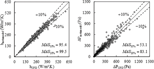
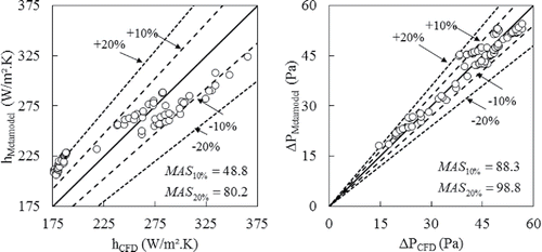
A design of experiments (DoE) containing 7096 samples generated using Latin hypercube sampling (LHS; McKay et al. Citation1979) was simulated using PPCFD. An effective 3286 samples were used to create the metamodels, which were tested against 961 random designs (). The accuracy of the metamodel is measured by the maximum acceptance score (MAS); if the percentage of the random predicted responses within eth is higher than the remainder of 1 – eth (Equation Equation14(14) ) then the metamodel is acceptable. Typically, the deviation threshold varies between 5% to 10%. However, such level of accuracy could not be obtained for pressure drop, for which the MAS is satisfied for a threshold of 20%. Additionally, the coefficients of determination for heat transfer and pressure drop are, respectively, 98.9% and 95.7%, thus showing a relative strong data correlation.
(15)
AAO and verification
A MO optimization problem with two objective functions is employed, including minimizing airside pressure drop and minimizing total envelope volume. Three optimization problems are investigated, each including additional constraints in a step-wise manner, bridging the gap between theoretical and real (i.e., NTHX-001). The last optimization problem entails finding optimum designs with similar manufacturing constraints imposed to the NTHX-001, yet with a thinner wall thickness.
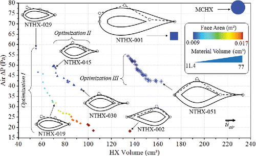
The results ofthe three optimization problems () show very interesting designs and insights. The addition of constraints from optimization I to III clearly shows the boundary of the feasible domain translating right and upward. The first optimization problem contains the best designs in the plot however at a cost of having larger face area. The discussion in the first and second order analysis pointed out that reducing tube diameter, although improves thermal performance, it also increases friction. One way to circumvent the high-pressure drop is by reducing air velocity which results in larger face area designs. However, in this case, the shape parameterization allowed the optimizer to find thermal-hydraulic compromises that resulted in designs with smaller face area, which could not have been done with round tubes. These results are in agreement with the shape parameterization study also in the first and second order analysis. The results from optimization II and III have minor differences between designs, mainly topology variables, but very similar shapes. All NTHX designs have more than 20% reduction in both pressure drop and envelope volume, while delivering similar capacity without fins, thus supporting the argument developed previously.
The CFD verification for the optimum designs () indicate that the metamodel prediction was not as accurate as estimated by the random verification; however, sufficiently accurate for the purposes of this study. The main reason for that are the heat transfer coefficient over-prediction, in between 10% and 20%, for the designs from optimization III. Since the designs from that Pareto set were very similar, the performances are also very similar compromising the optimizer heuristic search. The other optimization problems resulted in much more accurate prediction.
NTHX-001 testing and validation
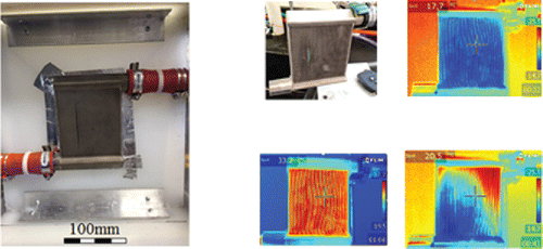
The prototype for the NTHX-001 () was fabricated using a metal additive manufacturing process on Titanium grade 5 for reliability purposes. Using infrared imaging it was assured there were no blockages () nor leakages.
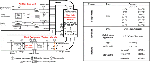
The prototype was tested in our wind tunnel facility () which follows the ASHRAE standards (ASHRAE Citation1987a, Citation1987b, Citation1987c, Citation2000, Citation2013). The test matrix comprised of 15 data points with 3 water flow rates and 5 airflow rates and a constant inlet approach temperature of 25 K (50% of the design inlet approach temperature). The average energy balance () deviation was 3.51%, while the average capacity uncertainty was of 4.57% and airside pressure drop was of 1.97%. The validation plots are shown in and .
Analysis of optimal designs
An important lesson from the optimization results is that the tube shape alone does not result in better performance; it is the combination of all design variables which results in better overall performance. As an example, the CFD simulations results for the NTHX-030 design () clearly show that the topology plays a major role in streamlining the flow (), thus minimizing the flow separation effects ().
Fig. 25. CFD results for the NTHX-030 design: a. magnitude velocity; b. velocity angle; c. turbulence intensity.
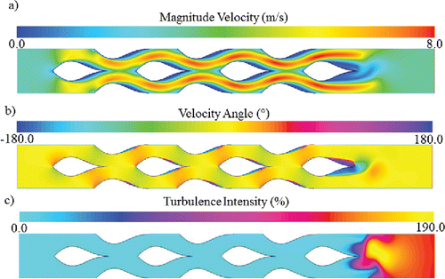
The addition of the shape variables adds another order of magnitude to the thermal-hydraulic trade-offs for every combination of tube size, number and configuration. Such level of flexibility gives more freedom to indirectly control flow regimes and attend any potential design constraint such as face area in many cases.
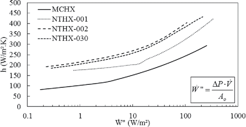
Two designs from Optimizations I and II were selected, respectively, and with support from the metamodels evaluated the overall performance for a wide range of Reynolds numbers. On the heat transfer coefficient versus friction power per unit area plot () one can conclude that these novel surfaces maintain their superior performance over the MCHX and NTHX-001 regardless the operating condition. Such behavior indicates the robustness of these designs which are not particularly better at the one design point.
Conclusions
The current article argued that conventional air-to-fluid HX's design concepts, and agreed upon practices to improve performance, are limited and should be re-thought and renovated in the light of modern modeling and manufacturing capabilities. In addition, an alternative approach was proposed suggesting that the focus of heat transfer enhancement should be devoted to tubes and potentially eliminating the use of conventional fin concepts. High level first- and second-order analyses shows how conventional fin concepts become unattractive at smaller characteristic lengths—in particular for tube diameters below 1.0 mm. An additional shape analysis was carried out to show how to overcome the challenges posed by small diameter tubes, i.e., high friction resistance. Next, a design problem was presented for a 1.0 kW air-to-water HX design, for which we have a state-of-the-art MCHX as a baseline. By employing small characteristic lengths with novel shapes, the authors designed a proof-of-concept (NTHX-001) that satisfies imposed manufacturing constraints while also achieving ∼20% reduction in size, ∼20% reduction in air pressure drop, ∼40% reduction in material volume, and ∼2% reduction in face area compared to the baseline. The NTHX-001 was fabricated using metal additive manufacturing techniques and tested in the wind tunnel facility. The predictions agreed with experimental data within 5% for overall capacity, 10% for airside heat transfer coefficient, and 15% for airside pressure drop. Finally, the authors presented a cost-effective and comprehensive design framework that allowed for the exploration of the potential of the proposed design methodology. Three design optimizations were carried out, each with small additions to the constraints bridging the theoretical to the feasible (i.e., NTHX-001). Optimum designs were very promising by showing potential size reduction of more than 50% with a 70% reduction in material while allowing for high flexibility in terms of face area, a condition that is very restrictive when using round tubes. From a performance viewpoint these designs are fundamentally sound; however, potential operation issues may occur. It is recommended that future studies investigate the impact of fouling and/or water bridging/frosting between tubes due to the small distances. Other physics to consider include vibration and noise, static/dynamic and thermal stresses.
Additional CFD results in the last section illustrate how the combination of shape and topology variables streamlines the flow, giving great control over flow regimes and the boundary layer attachment-disruption mechanism. Finally, it was demonstrated that these novel designs are very robust and they maintain higher performance over the baseline over a wide range of operating conditions.
Nomenclature
| Acs | = | cross section area m2 |
| Afin | = | fin surface area m2 |
| Afr | = | frontal face area m2 |
| Ao | = | total surface area m2 |
| At | = | tube syrface area m2 |
| C | = | heat capacitance rate W/K |
| Cf | = | skin friction coefficient - |
| cp | = | specific heat J/kg.K |
| D | = | depth mm |
| Dh | = | tube hydraulic diameter m |
| Dhin | = | in-tube hydraulic diameter mm |
| Dhs | = | surface hydraulic diameter mm |
| Do | = | outer diameter mm |
| e | = | absolute relative difference - |
| f | = | friction factor - |
| FPI | = | fins per inch 1/in |
| Fs | = | grid factor of safety - |
| GCI | = | grid convergence index - |
| h | = | heat transfer coefficient W/m2.K |
| ht | = | tube height mm |
| hx | = | local heat transfer coefficient W/m2.K |
| k | = | thermal conductivity W/m.K |
| k | = | turbulent kinetic energy m2/s |
| L | = | tube length mm |
| Lc | = | characteristic length mm |
| ṁ | = | mass flow rate g/s |
| Nf | = | number of fins - |
| Nr | = | number of tube rows (transverse) - |
| Nt | = | number of tube rows (longitudinal) - |
| Nu | = | Nusselt number - |
| p | = | spatial order of accuracy - |
| p* | = | observed order of accuracy - |
| p** | = | effective order of accuracy - |
| P | = | pressure Pa |
| P | = | curve length (tube perimeter) mm |
| Pl | = | tube longitudinal pitch mm |
| Pr | = | Prandtl number - |
| Pt | = | tube transversepitch mm |
| Q | = | heat transfer rate W |
| r | = | grid refinement ratio - |
| Re | = | Reynolds number - |
| rPl | = | longitudinal pitch ratio (Pl/Do) - |
| rPt | = | transverse pitch ratio (Pt/Do) - |
| T | = | temperature K |
| U | = | velocity m/s |
| UA | = | thermal conductance W/K |
| uc | = | mean velocity at minimum free flow area m/s |
| uoo | = | uniform velocity m/s |
| Ẇ′ | = | friction power per unit area W/m2 |
| wt | = | tube width mm |
| xcp | = | x-coordinate control point mm |
| ycp | = | y-coordinate control point mm |
| ΔP | = | pressure drop Pa ΔP |
Greek letters
| δt | = | tube thickness mm |
| ϵM | = | eddy diffusivity m2/s |
| μ | = | dynamic viscosity Pa.s |
| ρ | = | density kg/m3 |
| σ | = | contraction ratio (u/umax) - |
| α | = | thermal diffusivity m2/s |
Funding
The current study had support from the United States Department of Energy Grant Number DE-EE0006114 and the Modeling and Optimization Consortium of the Center for Environmental Energy Engineering at the University of Maryland.
References
- Abdelaziz, O., S. Azarm, V. Aute, and R. Radermacher. 2010. Approximation-assisted optimization for novel compact heat exchanger designs. HVAC&R Research 16(5):707–28.
- ANSYS. 2014. ANSYS Fluent 14.6. s.l.:s.n.
- ANSYS. n.d. Gambit 2.4.6. s.l.:s.n.
- Arora, A., P. Subbarao, and R. Agarwal. 2016. Development of parametric space for the vortex generator location for improving thermal compactness of an existing inline fin and tube heat exchanger. Applied Thermal Engineering 98:727–42.
- ASHRAE. 1987a. ANSI/ASHRAE Standard 41.2–1987, Standard Methods for Laboratory Airflow Measurement., s.l. Atlanta: ASHRAE.
- ASHRAE. 1987b. ANSI/ASHRAE Standard 41.3–1987, Standard Method for pressure Measurement., s.l. Atlanta: ASHRAE.
- ASHRAE. 1987c. ANSI/ASHRAE Standard 41.6–1987, Method for Measurement of Moist Air PropertiesANSI/ASHRAE Standard 41.6–1987, Method for Measurement of Moist Air Properties, s.l. Atlanta: ASHRAE.
- ASHRAE. 2000. ANSI/ASHRAE Standard 33–2000, Method of Testing Forced Circulation Air Cooling and Air Heating Coil, s.l. Atlanta: ASHRAE.
- ASHRAE. 2013. ANSI/ASHRAE Standard 41.1–2013, Standard Method for Temperature Measurement., s.l. Atlanta: ASHARE.
- ASME. 2009. Standard for Verification and Validation in Computational Fluid Dynamics and Heat Transfer—ASME V&V 20–2009. New York, NY: ASME.
- Atkinson, K., R. Drakulic, M. Heikal, and T. Cowell. 1998. Two! and three!dimensional numerical models of fow and heat transfer over louvred fin arrays in compact heat exchangers. International Journal of Heat and Mass Trasfer 41:4063–80.
- Bacellar, D., O. Abdelaziz, V. Aute, and T. Radermacher. 2015. Novel heat exchanger design using Computational Fluid Dynamics and Approximation Assisted Optimization. Chicago, ASHRAE Winter Conference, pp. 1–8.
- Bacellar, D., V. Aute, O. Abdelaziz, and R. Radermacher, 2014a. Design of Novel Air-to-Refrigerant Heat Exchangers Using Approximation Assisted Optimization. Las Vegas, NV, ASME Verification and Validation Symposium.
- Bacellar, D., J. Ling, O. Abdelaziz, V. Aute, and R. Radermacher. 2014b. Multi-scale modeling and Approximation Assisted Optimization of bare tube heat exchangers. Kyoto, Japan, IHTC, pp. 1–15.
- Cavazzuti, M., and M. Corticelli. 2008. Optimization of heat exchanger enhanced surfaces thorugh multiobjective genetic algorithms. Numerical Heat Transfer 54:603–24.
- Chen, H.-T., Y.-S. Lin, P.-C. Chen, and J.-R. Chang. 2016. Numerical and experimental study of natural convection heat transfer characteristics for vertical plate fin heat exchangers with various diameters. International Journal of Heat and Mass Transfer 100:320–31.
- Churchill, S. 1977. Frictional equation spans all fluid flow regimes. Chemical Engineering 84:91–2.
- Cowell, T., M. Heikal, and A. Achaichia. 1995. Flow and heat transfer in compact louvered fin surfaces. Experimental Thermal and Fluid Science 10:192–9.
- Cressie, N. 1993. Statistics for Spatial Data. New York, NY: John Wiley & Sons.
- Deb, K. 2001. Genetic algorithms for optimization. Kanpur, India: KanGAL Report No. 2001002.
- DeJong, N., and A. Jacobi. 2003. Localized flow and heat transfer interactions in louvered-fin arrays. International Journal of Heat and Mass Transfer 46:443–55.
- Dittus, F., and L. Boelter. 1985. Heat transfer in automobile radiators of the tubular type. International Communications in Heat and Mass Transfer 12(1):3–22.
- Duplain, E., and B.R. Baliga. 2009. Computational optimization of the thermal performance of internally finned ducts. International Journal of Heat and Mass Transfer 52:3929–42.
- Fabbri, G. 1997. A genetic algorithm for fin profile optimization. International Journal of Heat and Mass Transfer 40(9):2165–72.
- Fabbri, G. 1998. Heat transfer optimization in internally finned tubes under laminar flow conditions. International Journal of Heat and Mass Transfer 41(10):1243–53.
- Foli, K., T. Okabe, M. Olhofer, Y. Jin, and B. Sendhoff. 2006. Optimization of micro heat exchanger: CFD, analytical approach and multi-objective evolutionary algorithms. International Journal of Heat and Mass Transfer 49:1090–9.
- Fujii, M., Y. Seshimo, and G. Yamanaka. 1988. Heat transfer and pressure drop of perforated surface heat exchanger with passage enlargement and contraction. International Journal of Heat and Mass Transfer 31:135–42.
- Gholami, A., M.A. Wahid, and H.A. Mohammed. 2014. Heat transfer enhancement and pressure drop for fin-and-tube compact heat exchangers with wavy rectangular winglet-type vortex generators. International Communications in Heat and Mass Transfer 54:132–40.
- Gnielinski, V. 1976. New equations for heat and mass transfer in turbulent pipe and channel flow. International Chemical Engineering 16(2):359–68.
- Gosselin, L., M. Tye-Gingras, and F. Mathieu-Potvin. 2009. Review of utilization of genetic algorithms in heat transfer problems. International Journal of Heat and Mass Transfer 52:2169–88.
- Hajek, J. 2007. Parameterization of airfoils and its application in aerodynamic optimization. Republic, WDS'07 Proceedings of Contributed Papers, Prague, Czech.
- Hilbert, R., G. Janiga, R. Baron, and D. Thevenin. 2006. Multi-objective shape optimization of a heat exchanger using parallel genetic algorithms. International Journal of Heat and Mass Transfer 49:2567–77.
- Hsieh, C.-T., and J.-Y. Jang. 2006. 3-D thermal-hydraulic analysis for louver fin heat exchangers with variable louver angle. Applied Thermal Engineering 26:1629–39.
- Huang, D., R.-J. Zhao, Y. Liu, and D.-B. Yi. 2014a. Effect of fin types of outdoor fan-supplied finned-tube heat exchanger on periodic frosting and defrosting performance of a residential air-source heat pump. Applied Thermal Engineering 251–60.
- Huang, L., V. Aute, and R. Radermacher. 2014b. A model for air-to-refrigerant microchannel condensers with variable tube and fin geometries. International Journal of Refrigeration 40:269–81.
- Huang, L., V. Aute, and R. Radermacher. 2015. A survey of optimization formulations and techniques for the design of heat exchangers using lower GWP refrigerants. ASHRAE Winter Conference. Chicago, IL.
- Huisseune, H., C. T'Joen, P. De Jaeger, B. Ameel, S. De Schampheleire, and M. De Paepe. 2013. Performance enhancement of a louvered fin heat exchanger by using delta winglet vortex generators. International Journal of Heat and Mass Transfer 56:475–87.
- Ito, Y., N. Inokura, and T. Nagasaki. 2014. Conjugate heat transfer in air-torefrigerant airfoil heat exchangers. Journal of Heat Transfer 136:08170301–12.
- Jacobi, A., and R. Shah. 1995. Heat transfer surface enhancement through the use of longitudinal vortices. Experimental Thermal and Fluid Sciences 11(3):295–309.
- Jacobi, A.M., and R.K. Shah. 1998. Air-side flow and heat transfer in compact heat exchangers: a discussion of enhancement mechanisms. Heat Transfer Engineering 19(4):29–41.
- Jiang, H., V. Aute, and R. Radermacher. 2006. CoilDesigner: A general purpose simulation and design tool for air-to-refrigerant heat exchangers. International Journal of Refrigeration 29:601–10.
- Joardar, A., and A. Jacobi. 2005. Impact of leading edge delta-wing vortex generators on the thermal performance of a flat tube, louvered-fin compact heat exchanger. International Journal of Heat and Mass Transfer 48:1480–93.
- Kandlikar, S. 2007. A roadmap for implementing microchannels in refrigeration and air-conditioning systems-current status and future directions. Heat Transfer Engineering 28(12):973–85.
- Kandlikar, S. 2010. History, advances, and challenges in liquid flow and flow boiling heat transfer in microchannels: A critical review. Proceedings of the 14th International Heat Transfer Conference, Washington, DC.
- Kasagi, N., Y. Suzuki, N. Shikazono, and T. Oku. 2003. Optimal design and assessment of high performance micro bare-tube heat exchangers. Proc. 4th Int. Conf. on Compact Heat Exchangers and Enhancement Technologies for the Process Industries, Crete, Greece.
- Kays, W.M. 1960. The basic heat transfer an flow friction characteristics of six compact high-performance heat transfer surfaces. Journal of Engineering for Power 82(1):27–34.
- Kays, W., and A. London. 1984. Compact Heat Exchangers, 3rd Ed. New York, NY: McGraw-Hill.
- Kim, M., and C. Bullard. 2002. Air-side thermal hydraulic performance of multi-louvered fin aluminum heat exchangers. International Journal of Refrigeration 25:390–400.
- Lavasani, A.M., H. Bayat, and T. Maarefdoost. 2014. Experimental study of convective heat transfer from in-line cam shaped tube bank in crossflow. Applied Thermal Engineering 65:85–93.
- Lee, J., and K.S. Lee. 2013. Correlations and shape optimization in a channel with aligned dimples and protrusions. International Journal of Heat and Mass Transfer 64:444–51.
- Leu, J., M. Liu, J.-S. Liaw, and C.C. Wang. 2001. A numerical investigation of louvered fin-and-tube heat exchangers having circular and oval tube configurations. International Journal of Heat and Mass Transfer 44:4235–43.
- Li, J., S. Wang, J. Chen, and Y.-G. Lei. 2011. Numerical study on a slit fin-and-tube heat exchanger with longitudinal vortex generators. International Journal of Heat and Mass Transfer 54:1743–51.
- Li, Z., J.H. Davidson, and S. Mantell. 2004. Heat transfer enhancement using shaped polymer tubes: Fin analysis. Journal of Heat Transfer 126:211–8.
- Liu, X., J. Yu, and G. Yan. 2016. A numerical study on the air-side heat transfer of perforated finned-tube heat exchangers with large fin pitches. International Journal of Heat and Mass Transfer 100:199–207.
- Lotfi, B., M. Zeng, B. Sunden, and Q. Wang. 2014. 3D numerical investigation of flow and heat transfer characteristics in smooth wavy fin-and-elliptical tube heat exchangers using new type vortex generators. Energy 73:233–57.
- McKay, M., R. Beckman, and W. Conover. 1979. A comparison of three methods for selecting values of input variables in the analysis of output from a computer code. Technometrics 21:239–45.
- Min, J., and R.L. Webb. 2004. Numerical analyses of effects of tube shape on performance of a finned tube heat exchanger. Journal of Enhanced Heat Transfer 11(1):61–73.
- Mohammed, H., P. Gunnasegaran, and N. Shuaib. 2011. Influence of channel shape on the thermal and hydraulic performance of microchannel heat sink. International Communications in Heat and Mass Transfer 38:474–80.
- Nobile, E., F. Pinto, and G. Rizzetto. 2006. Geometric parameterization and multiobjective shape optimization of convective periodic channels. Numerical Heat Transfer, Part B: Fundamentals 50:425–53.
- Nouri-Borujerdi, A., and A.M. Lavasani. 2007. Experimental study of forced convection heat transfer from cam shaped tube in cross flows. International Journal of Heat and Mass Transfer 50:2605–11.
- Oberkampf, W., and C. Roy. 2010. Verification and Validation in Scientific Computing. Cambridge, UK: Cambridge University Press.
- Onishi, H., A. Yamamoto, Y. Tada, and A. Takimoto. 2014. Heat Transfer Performance of Finless Heat Exchanger Using Airfoil-Shaped Tubes with Extended Leading Or Trailing Edge Section. Kyoto, Japan: IHTC-15, pp. 1–12.
- Paitoonsurikarn, S., N. Kasagi, and Y. Suzuki. 2000. Optimal design of micro bare-tube heat exchanger. Proceedings of Symposium on Energy Engineering, Hong Kong, China, pp. 972–979.
- Patankar, S. 1980. Numerical heat transfer and fluid flow. First ed. Washington, DC: McGraw-Hill.
- Perrotin, T., and D. Clodic. 2004. Thermal-hydraulic CFD study in louvered fin-and-flat-tube heat exchangers. International Journal of Refrigeration 27:422–32.
- Private communications. 2010.
- Queipo, N., R. Devarakonda, and J. Humphrey. 1994. Genetic algorithms for thermosciences research: Application to the optimized cooling of electronic components. International Journal of Heat and Mass Transfer 37(6):893–908.
- Ranut, P., G. Janiga, E. Nobile, and D. Thevenin. 2014. Multi-objective shape optimization of a tube bundle in cross-flow. International Journal of Heat and Mass Transfer 68:585–98.
- Roach, P.J. 1997. Quantification of uncertainty in computational fluid dynamics. Annual Review of Fluid Mechanics 29:123–60.
- Roy, C.J., and W.L. Oberkampf. 2011. A comprehensive framework for verification, validation, and uncertainty quantification in scientific computing. Computational Methods Applied to Mechanical Engineering 200:2131–44.
- Saji, N., S. Nagai, K. Tsuchiya, H. Asakura, and M. Obata. 2001. Development of a compact laminar flow heat exchanger with stainless stell micro-tubes. Physica C 354:148–51.
- Salviano, L., D. Dezan, and J. Yanaghiara. 2016. Thermal-hydraulic performance optimization of inline and staggered fin-tube compact heat exchangers applying longitudinal vortex generators. Applied Thermal Engineering 95:311–29.
- Schumann, U. 1977. Realizability of Reynolds‐stress turbulence models. Physics of Fluids 20(5):721–5.
- Shah, R., and D. Sekulic. 2003. Fundamentals of Heat Exchanger Design. Hoboken, NJ: John Wiley & Sons.
- Shih, T., and J. Zhu. 1994. A New Reynolds Stress Algebraic Equation Model. Cleveland, OH: NASA Lewis Research Center.
- Silva, D., C. Hermes, and C. Melo. 2011. Experimental study of frost accumulation on fan-supplied tube-fin evaporators. Applied Thermal Engineering 1013–20.
- Sobieczky, H. 1998. Parametric airfoils and wings. Notes on Numerical Fluid Mechanics 68:71–88.
- Stalio, E., and M. Piller. 2006. Direct numerical simulation of heat transfer in converging-diverging wavy channels. Journal of Heat Transfer 129:769–77.
- Sui, Y., C.J. Teo, P.S. Lee, Y.T. Chew, and C. Shu. 2010. Fluid flow and heat transfer in wavy microchannels. International Journal of Heat and Mass Transfer 53:2760–72.
- Tafti, D., G. Wang, and W. Lin. 2000. Flow transition in a multilouvered fin array. International Journal of Heat and Mass Transfer 43:901–19.
- Tao, W., Y. Cheng, and T. Lee. 2007. 3D numerical simulation on fluid flow and heat transfer characteristics in multistage heat exchanger with slit fins. Heat and Mass Transfer 44:125–36.
- T'Joen, C., H. Huisseune, H.J., Caniere, H.J. Steeman, A. Willockx, and M. De Paepe. 2011. Interaction between mean flow and thermo-hydraulic behaviour in inclined louvered fins. International Journal of Heat and Mass Transfer 54:826–37.
- Tiller, P.L. 1995. The NURBS book. New York, NY: Springer.
- Tiwari, S., D. Maurya, G. Biwas, and V. Eswaran. 2003. Heat transfer enhancement in cross-flow heat exchangers using oval tubes and multiple delta winglets. International Journal of Heat and Mass Transfer 46:2841–56.
- Tuckerman, D., and R. Pease. 1981. High-performance heat sinking for VLSI. IEEE Electron Device Letters 2(5):126–9.
- Wang, C., J. Chang, and N. Chiou. 1999. Effects of waffle height on the air-side performance of wavy fin-and-tube heat exchangers. Heat Transfer Engineering 20(3):45–56.
- Wang, C.-C., Y.-M. Tsai, and D.-C. Lu. 1998. Comprehensive study of convex-louverand wavy fin-and-tube heat exchangers. Journal of Thermophysiscs and Heat Transfer 12(3):423–30.
- Webb, R., and N. Kim. 2005. Principles of Enhanced Heat Transfer. New York, NY: Taylor & Francis.
- Yun, J., and K. Lee. 1999. Investigation of heat transfer characteristics on various kinds of fin-and-tube heat exchangers with interrupted surfaces. International Journal of Heat and Mass Transfer 42:2375–85.
- Yun, J.-Y., and K.-S. Lee. 2000. Influence of design parameters on the heat transfer and flow friction characteristics of the heat exchanger with slit fins. International Journal of Heat and Mass Transfer 43:2529–39.
- Zhang, G.-M., et al. 2014. Analysis of flow and heat transfer characteristics around an oval-shaped cylinder. Journal of Heat Transfer 136.

