Abstract
Wet cooling coil surfaces can provide opportunities for microorganism growth. This biological fouling (biofouling) increases airside pressure drop and decreases airside heat transfer coefficient. Ultraviolet germicidal irradiation is one method to eliminate biofouling. The current article reports field measurements of changes in pressure drop and heat-transfer characteristics of fouled coils treated with ultraviolet germicidal irradiation designed for surface disinfection. Ultraviolet germicidal irradiation systems were installed in operating air-handling units with visibly fouled cooling coils at sites in Tampa, Florida and University Park, Pennsylvania. Pressure drop data were controlled for airflow and latent load, and overall heat-transfer coefficient data were controlled for heat exchanger entering conditions. Analysis of Tampa site data showed an initial mean 22.70% to 22.72% decrease (µ ± 2σ) in airside pressure drop and a mean 13.2% to 13.6% (µ ± 2σ) increase in overall heat-transfer coefficient. Longer-term improvement was 14.6% for the airside pressure drop and 15.7% for overall heat-transfer coefficient, though the decrease in pressure drop improvement was not able to be explained. The University Park, Pennsylvania site, cleaned by unaware maintenance personnel before data collection, had an initial mean 10.3% pressure drop improvement and 57.7% overall heat-transfer coefficient improvement, followed by a long-term 0% pressure drop improvement and 36.7% overall heat-transfer coefficient improvement.
Introduction
Cooling coils are heat exchangers in air-conditioning systems typically responsible for cooling and dehumidifying air to maintain space conditions. Dehumidification occurs when moisture condenses out of the air onto cold coil surfaces, which may often be wet in humid climates or when serving spaces with high latent loads. Microbes captured on the coil surface can grow there, resulting in biological fouling (biofouling). This impedes airflow and heat transfer, thereby increasing cooling system energy consumption. Common methods of controlling biofouling include mechanical cleaning, chemical cleaning, and ultraviolet germicidal irradiation (UVGI). The present investigation focuses on experimental assessment of the impact of coil UVGI on energy use, which, to date, has received little attention.
Cooling coils
A cooling coil is a fluid-to-air heat exchanger used to cool and dehumidify air. The air passes over rows of tubes through which a fluid flows, typically chilled water or refrigerant. The tubes pass through closely spaced fin sheets, typically 8–15 fins per inch (3.15–5.9 fins per cm), that enhance airside heat transfer. Coil face velocities are typically limited to 500 fpm (2.54 m/s) due to moisture carryover concerns, and design pressure drops typically fall between 0.50 and 1.00 in. wg (125 and 249 Pa).
Effects of coil fouling and biofouling
Cooling coil fouling is the build-up of organic and/or inorganic matter on heat-transfer surfaces. The current research focuses on fouling on the airside of the coil, which can increase flow resistance, thereby increasing fan energy use and/or reducing airflow rate. Reduced airside heat-transfer coefficients may increase waterside flow rates, decrease waterside ΔT, and reduce chiller coefficient of performance (COP). Biofouling can have additional adverse consequences for occupants, including odor (Kowalski Citation2006), spread of infection, and reduced work performance (Menzies et al. Citation2003).
Several studies report the effects of cleaning a fouled cooling coil, though the majority deal with lab experiments rather than field studies, and deposition-based fouling rather than growth-based biofouling. A case study of two air-handling units (AHUs) serving part of a 34-story office building in New York City reported a 14% decrease in pressure drop across the coils, a 25% increase in efficiency of sensible heat transfer, and a 10% increase in efficiency of latent heat transfer (Montgomery and Baker Citation2006). Coil cleaning was estimated to have the potential to reduce HVAC system energy use by 10% to 15%.
A laboratory study reported a 6% to 30% increase in pressure drop and –4% to 14% decrease in heat-transfer coefficient (Yang et al. Citation2007b) due to fouling, which resulted in an estimated 1% to 10% decrease in energy efficiency ratio (EER; Yang et al. Citation2007a). The heat-transfer coefficient increased at low levels of fouling due to the increase in local velocity, but this was balanced by increased thermal resistance as fouling accumulated.
Siegel and colleagues (Citation2002) estimated a doubling of evaporator pressure drop in 7.5 years due to particulate fouling, resulting in an overall system efficiency reduction of less than 5%, but note that the value may be larger. Waring and Siegel (Citation2008) reported up to a 200% increase in pressure drop. Both studies note the influence of filter minimum efficiency reporting value (MERV) rating on deposition-based fouling accumulation.
Ali and Ismail (Citation2008) used fouling material collected from room air conditioners to simulate a year of particulate deposition fouling on a direct expansion (DX) cooling coil installed in a laboratory apparatus. The COP of the unit dropped from an initial clean value of 2.82 to 1.89, 1.73, and 1.23 after the injection of 100, 200, and 300 g of fouling material, respectively.
A laboratory study seeded a cooling coil with Aspergillus, encouraged “accelerated” growth for 28 days, and then recorded the airside pressure drop and heat-transfer coefficient resulting from different levels of fouling from that point forward (Pu et al. Citation2010). Measurements at different levels of fouling showed an increase in airside pressure drop ranging from 19.8% to 43.1%, and a change in heat-transfer coefficient ranging from an initial increase of 13.1% to a decrease of 15.6% as fouling accumulated.
UVGI disinfection theory
The ultraviolet spectrum is divided into several wavelength bands, and the wavelength of 265 nm in the UVC band is the most effective for inactivation of microorganisms (ASHRAE Citation2016b). Low-pressure mercury vapor lamps primarily produce 254 nm UVC. This wavelength is near-optimal in its germicidal characteristics (approximately 90% as effective as 265 nm), and so these lamps are the preferred source of germicidal radiation. UVGI “inactivates” microbes: damaging their DNA to prevent reproduction. Inactivated microbes may still be air or surface contaminants to the extent that they function as allergens.
To a first approximation, UVGI disinfection has an exponential dose-response (ASHRAE Citation2016b):
(1) where S is the surviving fraction of the initial population, Nt is the number of organisms after exposure time t [s], N0 is the initial number of organisms, k [cm2/μW-s] is the microorganism specific rate constant, and I [μW/cm2] is the average germicidal irradiance received by microorganisms.
The rate constant k represents the susceptibility of a microorganism to UVC, and is typically determined experimentally. The value of k varies widely between microbe type, and reported k-values for a single species can also vary due to differences in measurement protocol (Kowalski Citation2009).
UVGI for coil cleaning
The principles of UVGI coil cleaning technology are described in detail by ASHRAE (Citation2015, Citation2016b) and Kowalski (Citation2009), which review numerous sources on the subject. UVGI devices may be installed upstream, downstream, or on both sides of the coil to inactivate microbes, although downstream installation tends to be preferred because it also irradiates the condensate pan. Operation of UVC lamps may be continuous or intermittent. Coil irradiation systems treat stationary surfaces, and so typically deliver less power (10% or less) than systems designed for air disinfection, which disinfects air moving past at relatively high speeds.
Studies cited by Kowalski (Citation2009) reported impacts on surface microbial concentrations but did not address energy use. Bahnfleth (Citation2011) provided a more recent review that included a summary of published reports of effectiveness. At the time, no peer reviewed studies of energy impacts of coil UVGI had been published. Subsequently studies are reviewed in the following text.
A brief trade magazine article (Steril-Aire Citation2000 a, Citation2000b) reported that a facility installed UVGI in twenty AHUs, experienced a 28% reduction in HVAC energy use, and was then able to meet its peak cooling load with three chillers instead of four due to a better waterside ΔT. Unfortunately, the reporting of energy savings was missing many details, including explanation of the calculation procedures.
The installation of UVGI installations in two Florida hospital system AHUs resulted in a 61% and 42% decrease in airside pressure drop according to Keikavousi (Citation2004). Increases in coil face air velocity and decrease in leaving wet-bulb temperature were also noted.
A California Energy Commission study (Arent Citation2006) found a 1% to 2% airflow improvement in constant air volume (CAV) systems at schools due to the installation of coil cleaning UVC. No energy benefit was observed. Importantly, they note that little fouling was on the coils to begin with, so the results are not surprising.
A recent laboratory study reported a minimal difference between coil performance with and without UVGI: negligible pressure drop change and 3% to 6.4% improvement in heat transfer (Luongo et al. Citation2017). The low-impact in this case may be due in part to the dry climate (Denver, Colorado) and the use of new, clean coils. A field study in the hotter and more humid environment of Singapore noted 13% decrease in pressure drop and 10% increase in heat transfer resulting from the use of UVGI on a fouled coil (Wang et al. Citation2016).
In summary, a limited body of existing literature suggests that coil UVGI can have a significant impact on HVAC energy consumption, but many are trade journal case studies that are not well-documented, and others report only modest impact. The recent studies support these claims to the extent that they have demonstrated reductions in pressure drop and increases in heat-transfer coefficient, but do not provide verification of overall HVAC energy savings claims and estimates of cost effectiveness.
The current research aimed to quantify the energy use benefit of UVGI coil irradiation by measuring its effects on airside pressure drop and overall heat-transfer coefficient through a field study.
Experimental methods
Field experimental setup
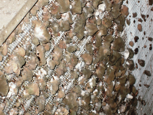
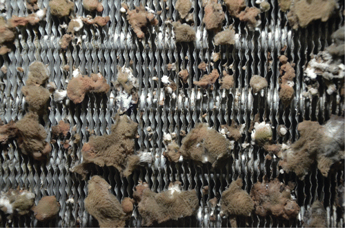
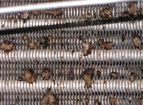
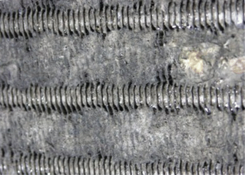
Data were collected at two field sites: one in Tampa, Florida and the other in University Park, Pennsylvania (PSU). Both were chosen based on a combination of factors: visibly fouled cooling coil, owner interest, researcher access, and climate. Climate influences the range of airflows, sensible loads, and latent loads. Tampa is a hotter and more humid climate that could require cooling year-round, influencing the potential for biological growth. The PSU site experiences hot and humid summer periods, but it is cold in the winter and does not require use of the cooling coil year-round. summarizes the buildings and their HVAC systems. The PSU site AHU had two staggered coils, and so characteristics for both are listed when applicable. Coils at both sites had visible fouling ( and ).
Table 1. Site and HVAC system characteristics.
Fig. 2. Close-up of fouling at PSU site, upstream side of coil. Note the accumulation of fouling at the space between the tubes.
lists the UVGI lamp characteristics. Lamps for both sites were selected by the manufacturer to provide a minimum average coil surface intensity of 200 μW/cm2 with a minimum point surface intensity of 50 μW/cm2, including a derating factor of 80% for end-of-life lamp output. UVGI system placement was based on location of visible fouling. Both sides of the Tampa coil were fouled, but fungal growth was most apparent on the downstream side, while the upstream side appeared to consist mostly of impacted material (e.g., insect wings). The PSU coil was fouled primarily on the upstream side.
Table 2. Field site UV lamp information.
Coil irradiance for both sites was measured using an ILT-1700 research radiometer with SED240 sensor heads, diffusers, and filters for the 254 nm UVC wavelength. Radiometer, sensor heads, and accessories were National Institute of Standards and Technology (NIST)-traceable calibrated (as a single unit) to an accuracy of 6.5% of reading. The sensor heads and accessories are not zero-thickness, so irradiance measurements are taken at a plane parallel to the coil, and the irradiance at the coil face is estimated using the inverse square law applied to a line source.
At the Tampa site, after 6 months of operation, the irradiance on the face of the coil averaged 325 μW/cm2 and with a minimum of 41 μW/cm2 in one corner. At PSU, irradiance on the upper coil after 26 months averaged 799 μW/cm2 with a minimum of 101 μW/cm2, while irradiance on the lower coil averaged 477 μW/cm2 with a minimum of 253 μW/cm2. These measurements confirmed proper sizing of the UVGI systems.
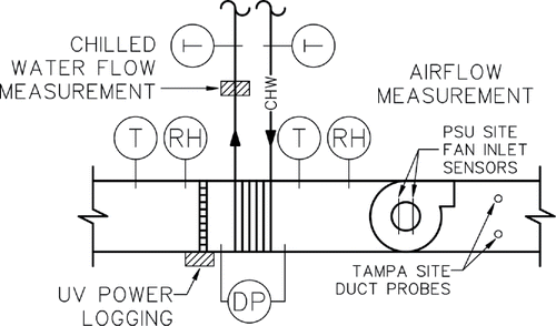
lists measurement points and associated instrumentation accuracies. shows a schematic of the measurement point locations. All points were used in the comparison of pressure drop and/or heat-transfer coefficient.
Table 3. Measurement instrumentation.
Test procedures
Data were collected passively during normal AHU operation. Other than brief periods of on-site testing during instrumentation testing, all data collection occurred when the AHUs were operating normally to heat, cool, and ventilate the spaces served in accordance with their existing control sequences. Data from all instrumentation points were continuously collected and logged to a custom data acquisition enclosure at simultaneous 1-minute intervals.
Due to coil operation conditions relying upon the actual cooling load on the AHUs, pre- and post-UVGI data collection periods each included at least 1.5 summer months. That is, pre-UVGI data collection could start at the beginning of a summer at the latest, and the UVGI system would then be activated mid-summer. This was adopted to capture pre- and post-UVGI coil operation at high sensible and latent loading.
After installation of monitoring equipment, but before collection of pre-UVGI data, the PSU site was cleaned by maintenance personnel unaware of its role in the research project. The cleaning consisted of application of a chemical spray foam. It did not remove all visible fouling from the cooling coil. Despite deviation from the planned protocol, data was collected to determine whether UVGI would have a measurable impact on a recently cleaned coil.
Data analysis procedures
Pressure drop
Pressure drop is a function of both airflow and latent load, with as much as a 33% decrease in pressure drop across a coil that changes from fully wet to fully dry (ASHRAE Citation2016 a). A direct comparison of all pressure drop data from the pre-UVGI period to the post-UVGI period would be valid only if near-identical distributions of airflow and latent load occurred during both. This was not the case, so methods that control for airflow and latent load were necessary.
A three-step binning method was developed to compare pre- and post-UVGI pressure drop while controlling for airflow and latent load:
| 1. | Establish the range of airflow and latent load based on extremes of collected data. | ||||
| 2. | Divide the range into several bins of airflow and latent load. | ||||
| 3. | Compare pre- and post-UVGI pressure drop data that are in the same bins. | ||||
Comparing all pre-UVGI data to all post-UVGI data also neglects the likelihood that there is a transitional period during which the condition of the coil changes from a relatively stable pre-UVGI state to another stable post-UVGI state. Comparison of post-UVGI monthly mean pressure drops with the mean of pre-UVGI data was used to determine when the transition ends.
Heat transfer
An enthalpy-based, overall heat-transfer coefficient (UA) was used to quantify changes in heat-transfer performance between pre-UVGI and post-UVGI values. Its calculation and use are described in detail by Wang et al. (Citation2016, Citation2017). It is based on an inverse application of chilled water-based cooling coil design and simulation models used in public domain yearly energy simulation software EnergyPlus (US DOE Citation2012, Citation2015) and developed by others (Brandemuehl Citation1993; Kuehn et al. Citation1998; Wetter Citation1998).
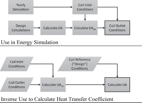
illustrates the forward use of the model in simulation of energy use and the inverse application to determine coil UA. The simulation software establishes the UA of the coil at design conditions using design load conditions and calculations. During forward modeling actual coil inlet conditions are used to adjust design coil UA to an operational UAop. UAop is then used to calculate the coil outlet conditions. The inverse application starts from data collected on operational inlet and outlet conditions, and calculates UAop. This value is then adjusted “back” to a UA at a set of reference conditions.
lists the variables used by the coil model in the energy simulation software. The variables in the “Coil Design” column define UA using an NTU-ϵ method. During yearly simulation (coil operation), there are different inlet variables at each timestep, and therefore, are also different outlet conditions. Airflow rate, waterflow rate, air inlet temperature, and water inlet temperature are used to modify UA to UAop. Again, this is process is inverted to calculate UA for data analysis.
Table 4. UA model use of input variables in simulation software.
UAop tends to be less than UA, indicating a reduction in heat-transfer ability at off-design, part load conditions. In the case of this research, the middle 90% of values of the ratio UAop/UA tended to be between 0.55 and 0.95.
lists the reference values used for the calculation of UA using the inverse method. These were chosen to match EnergyPlus software functionality that enables the user to directly specify coil UA at these nominal conditions to simulate coil fouling.
Table 5. Conditions for design UA value calculation.
Uncertainty analysis
Uncertainty propagation analysis followed the procedure outlined by ASHRAE (Citation2004). The uncertainty in a quantity that depends on other parameters that are themselves subject to uncertainty is given by Equation 2.
(2) where sf is the standard deviation of the calculated value, f is the calculated value, xi is an independent variable used in the calculation of f, and sxi is the standard deviation of variable xi. In EquationEquation 2
(2) , it is assumed that uncertainties of independent variables are normally distributed and uncorrelated.
The standard deviations of all measured data were based on the instrumentation accuracies listed in . If the instrumentation listed a constant accuracy, that was used. If the instrumentation listed accuracy as a percentage of reading, then the standard deviation was calculated for each data point.
For pressure drop, uncertainty was carried manually through calculation of averages of pre- and post-UVGI values, as well as the calculation of differences between the two. Due to the large number of data points collected, and the relatively small uncertainty of the pressure drop measurement equipment (standard deviation of ±0.14% of full scale, as shown in ), the standard deviation of average pressure drop for a bin rapidly decreases in size as the number of points increases:
(3) where smean is the standard deviation of a calculated mean, n is the number of points, and si is the standard deviation of a single measurement.
UA is calculated using all seven parameters listed in , and so requires the uncertainty associated with each. Due to the number of intermediary equations and the use of psychrometric functions, equation solving software Engineering Equation Solver (EES; Klein Citation2016) with uncertainty propagation functionality was used to calculate the uncertainty of UA at each timestep.
Results
Visual evidence of coil cleaning
Photos of the Tampa site show dramatic differences between the highly fouled pre-UVGI () and post-UVGI conditions (). Though the fouling had not been eliminated, it visibly changed, appearing desiccated and different in color. Typical UVGI industry practice is to mechanically clean an existing coil at the time of installation and rely on UVGI to keep the coil clean after. These results confirm the need for that practice. Photos of the PSU coil are not included, as they did not give a visual indication of fouling reduction.
Data pre-processing
Pre-processing of data was necessary to remove data that should not be included in analysis, including measurements during shutdown periods, physically unrealistic or impossible values, known periods of instrument malfunction, and values outside the limit of detection of instrumentation.
Other data was removed due to instrumentation readings that appeared to violate thermodynamic law and heat exchanger theory when used. This included issues such as cooling coil apparatus dew point temperatures lower than entering chilled water temperatures, or leaving chilled water temperatures higher than entering air temperatures.
Finally, a 15-minute centered moving average was applied to all data to smooth out higher-frequency transients and clarify trends.
At the Tampa site, data were collected for about 91,000 time steps before the UVGI lamps were turned on and for about 530,000 time steps after. This corresponds to about 63 days before and 368 days after. Pre-UVGI data were collected June 11, 2013 to July 8, 2013 and September 18, 2013 to November 1, 2013. Post-UVGI data were collected November 1, 2013 to December 19, 2014. Tampa data pre-processing removed approximately 20% of pre-UVGI data and 31% of post-UVGI, leaving 72,000 time steps (about 50 days) before the lamps were turned on and 364,000 (about 350 days) after.
At the PSU site, data were collected for about 117,000 time steps before the lamps were turned on, and about 473,000 time steps after. This corresponds to about 81 days pre-UVGI and 328 days post-UVGI. Pre-UVGI data were collected April 14, 2014 to July 17, 2014. Post-UVGI data were collected July 17, 2014 to October 1, 2015, with a 4-month gap during December 2014 and January through March 2015. PSU data pre-processing removed about 70% of pre-UVGI values and 82% of post-UVGI values, leaving about 36,000 time steps (about 24 days) before the lamps were turned on, and 96,000 (about 66 days) after the lamps were turned on. The majority of pre-processing data removal for the PSU site was due to limitations in the cooling coil model rendering timesteps unfit for comparison for both pressure drop and heat transfer. Without this limitation, the pre-UVGI data set would have been near 90,000 time steps, and the post-UVGI data set would have been near 440,000 time steps. This limitation of the cooling coil model is addressed more comprehensively in the Discussion section.
Pressure drop results
Tampa site
lists binning ranges and intervals used to compare pre- and post-UVGI pressure drop using the procedures noted in the Experimental Methods section.
Table 6. Binning range and interval for analysis of Tampa ΔP data.
shows example plots of pressure drop versus time. The initial point denotes the mean of all pre-UVGI data in the designated bin, while subsequent points are after the activation of UVGI. In bin (A) the change between pre- and post-UVGI pressure drop levels occurred in the first month, a pattern typical of other bins. This was consistent with anecdotal reports from manufacturers regarding the time frame in which UVGI will achieve maximum fouling reduction. After the first month there was variation of pressure drop, but it stayed well below the initial pre-UVGI value. Bin (B) has a higher airflow rate and latent load, and does not show a clear difference between pre- and post-UVGI performance. The value of ΔP decreased in the first month, but was lower than the values in later months. There is also the suggestion of a season-length cyclical element, though the reason for this was unable to be determined.
Fig. 7. Tampa mean airside pressure drop versus time for example bins; a. 3800–4000 cfm and 44.4–47.8 kBTU/h (1.79–1.89 m3/s and 13–14 kW latent load); b. 4000–4200 cfm and 51.2–54.6 kBTU/h (1.89–1.98 m3/s and 15–16 kW). Error bars are ±2% of full scale for illustration, as the calculated standard deviations using the point measurement error of 0.14% full scale were too small to be visible.
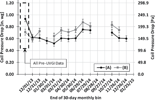
Gaps indata and unexpected patterns in post-UVGI behavior (i.e., the increase of pressure drop) made the data analysis challenging. Change occurring during the period of a month fits anecdotal engineering experience, and theoretically lessens the chance of confounding factors influencing later results. However, it is obvious that the behavior during the remaining months is unexpected, and unfortunately unexplained. UV, a well-established anti-germicidal technology, is not going to cause growth and increase pressure drop, but that does not change the fact that pressure drop increased. Given these limitations, results will be examined in both short- and long-term, and avoiding these limitations will be further addressed in the Discussion section.
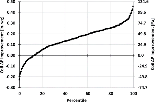
Between the pre-UVGI period and the end of the first month of UVGI operation (48 bin-to-bin comparisons), the mean ±2 standard deviations of pressure drop improved 0.2308 to 0.2311 in. wg (57.49–57.56 Pa), or 22.70% to 22.72% (an approximately 95% confidence interval). Median improvement was 0.243 in. wg (60.6 Pa), or about 24%. Comparing every post-UVGI bin with data to the pre-UVGI baseline (445 bin-to-bin comparisons) yielded a mean ±2 standard deviation improvement of 0.1484 to 0.1485 in. wg (36.96–36.98 Pa), or 14.59% to 14.60%. Median improvement was 0.158 in. wg (39.4 Pa), or 15.5%. is a percentile plot showing the improvement for all bins in all months. A net positive improvement was shown in 86.3%.
Though a clear reason for the discrepancy between short-term and long-term results was not found, the situation highlights the necessity of proper coil maintenance to deal with unexpected issues.
PSU site
lists the binning ranges and intervals used to compare pre- and post-UVGI pressure drop using the procedures noted in the Experimental Methods section.
Table 7. Binning range and interval for analysis of PSU ΔP data.
is a typical graph of pressure drop versus time. As before, month 0 denotes the mean of all pre-UVGI data, while later months are monthly means following the activation of UVGI. The data display a slight initial increase in the pressure drop and slow rate of subsequent increase. It is speculated that increasing pressure drop post-UVGI at the PSU site may have been due to accumulation of material after the initial cleaning rather than biofouling, but that cannot be confirmed by the collected data.
Fig. 9. PSU mean air side pressure drop versus time for example bins; a. 14,200–14,400 cfm and 57.9–68.2 kBTU/h (6.61–6.70 m3/s and 17.5–20.0 kW); b. 14,200–14,400 cfm and 68.2–76.8 kBTU/h (6.61–6.70 m3/s and 20.0–22.5 kW). Error bars are ±2% of full scale for illustration, as the calculated standard deviations using the point measurement error of 0.14% full scale were too small to be visible.
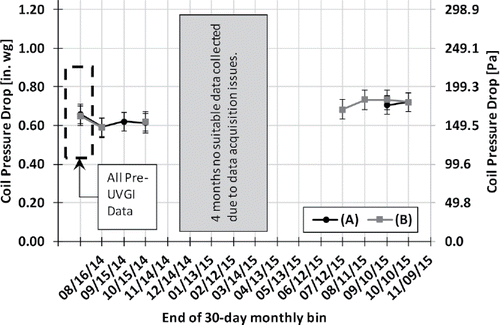
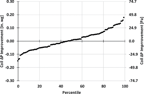
After the first month of UVGI operation (26 bin-to-bin comparisons), mean improvement ±2 standard deviations was 0.0688 to 0.0692 in. wg (17.15–17.23 Pa), or 10.31% to 10.36%, with a median improvement of 0.072 in. wg. (18.0 Pa), or 10.8%. However, the entire period of data collection (127 bin-to-bin comparisons) showed a very small degradation versus pre-UVGI conditions: a mean increase of 0.007 in. wg (1.7 Pa), or a 1% increase. The median was 0.001 in. wg (0.22 Pa), or a 0.13% increase. In practical terms, no significant difference was established over the data collection period. shows the spread of this data around a median of essentially zero.
Heat-transfer results
As noted previously, cooling coils typically transfer both sensible and latent heat, therefore, an enthalpy-based conductance is used to describe their performance, resulting in units of heat flow per unit enthalpy difference. Calculation details are given in the references cited at the beginning of the Heat Transfer subheading in the Methodology section (Wang et al. Citation2016, Citation2017). Nominal UA values were calculated for the inlet conditions tabulated in . Boxplot limits of 1.5 times the interquartile range were used to eliminate outliers, as calculated reference UA values should be the same (excluding the effects of measurement uncertainty and model approximations).
Tampa site
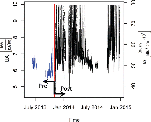
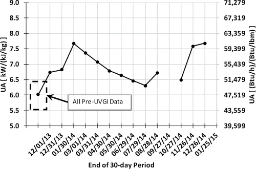
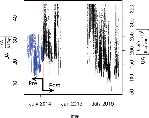
clearly shows an increase in post-UVGI UA values. However, there is also a seasonal variation in post-UVGI UA that made it impossible to conclude based on visual evidence alone that UVGI caused an increase in UA. UA was highest in mid-winter, declined in summer, and then increased again. Variation in UA correlated with variation in sensible heat ratio (SHR), total load, and latent load. This result was unexpected because, as noted previously, the value of UA was referenced to a single set of conditions, and therefore, should have had nearly the same value. Variation in the reference UA value is likely to be the result of limitations in cooling coil model assumptions. Several approaches to account for variation in UA in terms of the correlated parameters were made, but without success.
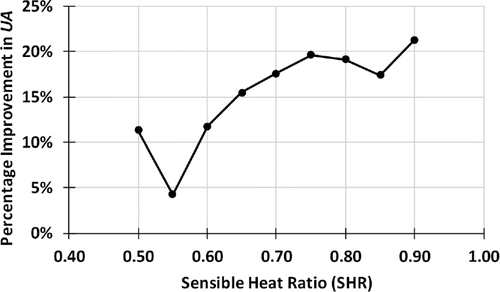
SHR is not accounted for in the procedure for calculating UA at a reference condition, so results were analyzed by SHR bin (similar to dividing up pressure drop data by airflow and latent load). Bins started at an SHR of 0.5 and ended at 0.90 with an increment of 0.05. A typical graph of UA improvement over time () shows that a significant amount of change happens after the first month of UVGI (similar to the time frame for the change in pressure drop), but there is an increase after, as well. Much like the pressure drop results, some periodicity was still apparent.
Based on the difference between the pre-UVGI period and the first month for all SHR bins, UA ±2 standard deviations (approximately a 95% confidence interval) improves 0.830 to 0.854 kW/(kJ/kg), or 13.2% to 13.6%, with a median of 0.875 kW/(kJ/kg). For all data bins collected post-UVGI, the mean of the difference in UA ±2 standard deviations was 0.980 to 0.990 kW/(kJ/kg), or an improvement of 15.6% to 15.8%, with a median of 1.02 kW/(kJ/kg). shows that more improvement occurs at higher values of SHR. This specific result will be addressed comprehensively in the Discussion section.
PSU site
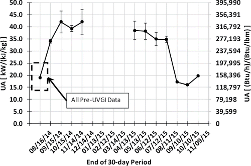
displays UA versus time. Like the Tampa site, there was an initial improvement in UA, followed by significant variation in post-UVGI values. Again, this variation was correlated with trends in SHR, total load, and latent load.
Results were again analyzed by binning via intervals of SHR: 0.5 to 0.95 in an increment of 0.05. Like the Tampa results, there was typically an increase in UA after the first month of UVGI. shows results for the 0.80 to 0.85 SHR bin, which is representative of others. Note that the values of UA are higher for the PSU site because airflow capacity is roughly three times that of the AHU at the Tampa site.
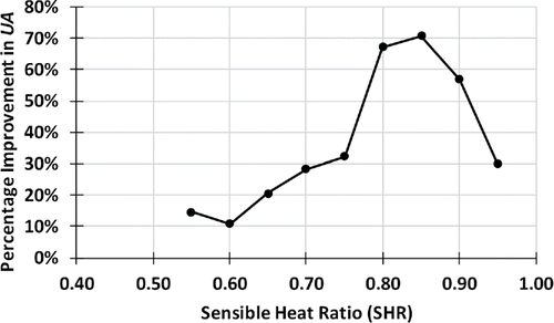
The mean improvement of UA ±2 standard deviations during the first month was 10.6 to 11.7 kW/(kJ/kg), or 54.8% to 60.2%, for all SHR bins with a median of 12.5 kW/(kJ/kg). The mean improvement ±2 standard deviations for the entire collection period was 6.5 to 7.7 kW/(kJ/kg), an improvement of 33.6% to 39.7% with a median of 5.2 kW/(kJ/kg). The relative improvement in pressure drop at PSU was essentially zero and improvement in UA was large, unlike the Tampa site, which showed similar magnitude in the improvement of both pressure drop and UA. Like the Tampa site, generally shows an increase in UA improvement as SHR increases, but then starts to decrease after an SHR of about 0.85. This specific result will be addressed comprehensively in the Discussion section.
Discussion
Field measurements were chosen in preference to laboratory studies so that naturally fouled coils could be observed in realistic operating conditions. The consequences of choosing a purely passive monitoring of natural conditions included additional data noise, remote access issues, the inability to employ a rigorous experimental design for the data collection, and unforeseen confounding factors. The existing literature spans laboratory and field studies, each with their own benefits and limitations. In the case of this field study, the passive data collection would have been aided significantly by regular on-site airflow measurements at a pre-determined set of airflow rates, similar to the methodology employed by Wang et al (Citation2016, Citation2017).
The results reflect the performance of two buildings in two different climates, and cannot be assumed to generalize well. The degree of improvement resulting from UVGI coil irradiation may vary significantly from installation to installation depending on application conditions. For example, coils located in temperate or dry climates with long periods of dry coil operation could be expected to benefit less than those in hot, humid climates with year-round wet coil operation.
The implications of the Tampa site results are clear. The application of UVGI reduced the pressure drop and increased the heat-transfer coefficient, mitigating issues caused by the biofouling. The appearance of the biological growth was markedly different after irradiation. Both absolute and percentage change in UA and ΔP are similar to that described by Wang et al. (Citation2016, Citation2017), which examined a system of roughly 8200 cfm (3.9 m3/s) versus the 6000 cfm (2.8 m3/s) of the Tampa AHU. Time period for changes to occur are consistent with Wang et al. (Citation2016, Citation2017) and manufacturer experience.
The Penn State results were more difficult to interpret for several reasons. Cleaning of the coil prior to collection of baseline data was clearly a factor in the small observed changes in pressure drop, although other factors such as the less humid climate and nonviable fouling material (i.e., biological or nonbiological impacted material) also may have played a role.
Reasons for the large concurrent increase in heat-transfer coefficient can only be conjectured. Previous studies have observed increases in heat transfer after coil loading that were attributed to increased velocity through the coil with low levels of fouling (Pu et al. Citation2010; Yang et al. Citation2007b), but the improvement was 5% to 15%, rather than the 36.7% to 57.5% observed at the PSU site. It was speculated that UVGI resulted in removal of biological fouling that affected heat transfer, while nonbiological fouling was the controlling factor with respect to pressure drop. However, there were no data available to test this hypothesis. Though the magnitude of UA improvement at the PSU site looks promising, the concurrent small to zero improvement of pressure drop characteristics suggests caution.
Both sites showed a higher percentage improvement at a higher SHR. This was determined to be primarily a result of the cooling coil model. The model, when used as intended in simulation software, produces air outlet conditions near saturation. However, when the model is applied inversely to data where the cooling coil air outlet conditions are not near saturation, it will produce unrealistically large values of UA or an error (e.g., natural log of zero). Cooling coil outlet conditions not near saturation are indicative of conditions with a high SHR, with fully sensible cooling (SHR) being the simplest example.
Conclusion
In two field studies, UVGI coil irradiation reduced airside pressure drop and increased UA of cooling coils with degraded performance due to biofouling, though the magnitude of the improvement varies. Analysis of field measurements in an HVAC system in Tampa, Florida indicated a mean pressure drop reduction of 22.7%/14.6% (short-term/long-term) and an increase in UA of 13.4%/15.7% (short-term/long-term). Analysis of field measurements in an HVAC system in University Park, Pennsylvania indicated a small decrease in pressure drop initially (10.3%), but a mean change of zero long-term. Conversely, heat-transfer coefficient increased 57.5%/36.7% (short-term/long-term). However, the coil at this site was inadvertently cleaned just prior to the start of baseline data collection and cannot be directly compared with the Tampa site.
Changes from coil irradiation occurred over a relatively short period of time, 1 month or less. This is consistent with what is claimed by industry professionals.
There is clearly a relationship between variation in heat-transfer coefficient and the SHR of the cooling load, but a quantitative physical model of it could not be derived. The extent to which this trend is a physical difference or one related to limitations of the cooling coil model used is not clear.
Results of this study support longstanding industry claims that UVGI cooling coil treatment can decrease pressure drop and increase heat-transfer coefficient. However, there remain many aspects of this technology that should be investigated for both scientific and practical reasons. The number of studies of the energy use impact of coil UVGI is very small and needs to be expanded, both to test the findings of this study and to further explore the impact of climate and occupancy type. A simple cooling coil model applicable to all conditions would enable more collected data to be included in analyses. Studies of the effect of fouling mitigation on chilled water plant energy use and on direct expansion systems are needed. Furthermore, the literature contains little applicable data on biofouling that would allow prediction of fouling rates. Studies of the process of biofouling that would parameterize it in a way that could be used to predict performance impacts would be of general value.
Funding
The authors acknowledge with gratitude financial support for completion of this work by ASHRAE under RP-1738, initial funding by the Consortium for Building Energy Innovation (CBEI), donation of UV equipment and design services by UVDI, Inc., engineering services by Ross Montgomery of Quality Systems and Technology, Inc., and to the owners for access to the sites.
References
- Ali, A.H.H., and I.M. Ismail. 2008. Evaporator air-side fouling: Effect on performance of room air conditioners and impact on indoor air quality. HVAC&R Research 14(2):209–19.
- Arent, J. 2006. Advanced HVAC Systems for Improving Indoor Environmental Quality and Energy Performance of California K-12 Schools: Attachment IV Final Report, Effectiveness of UVC Technology for Improving School Performance. Sacramento, CA: California Energy Commission.
- ASHRAE. 2004. ASHRAE Guideline 2–1986 (RA 96): Engineering Analysis of Experimental Data. Atlanta: ASHRAE.
- ASHRAE. 2015. Ultraviolet Air and Surface Treatment. In ASHRAE Handbook-HVAC Applications. Atlanta: ASHRAE.
- ASHRAE. 2016a. Air-Cooling and Dehumidifying Coils. In ASHRAE Handbook-HVAC Systems and Equipment. Atlanta: ASHRAE.
- ASHRAE. 2016b. Ultraviolet Lamp Systems. In ASHRAE Handbook-HVAC Systems and Equipment. Atlanta: ASHRAE.
- Bahnfleth, W. 2011. UVGI in air handlers. ASHRAE Journal 53(4):71–2.
- Brandemuehl, M.J. 1993. HVAC2 Toolkit: Algorithms and Subroutines for Secondary HVAC Systems Energy Calculations. Atlanta: ASHRAE.
- Keikavousi, F. 2004. UVC: Florida Hospital Puts HVAC Maintenance Under a New Light. Engineered Systems 21:60–3.
- Klein, S.A. 2016. Engineering Equation Solver (EES) software (version 9.950-3D). f-Chart Software.
- Kowalski, W. 2006. Aerobiological Engineering Handbook. New York, NY: McGraw-Hill.
- Kowalski, W. 2009. Ultraviolet Germicidal Irradiation Handbook: UVGI for Air and Surface Disinfection. Berlin Heidelberg: Springer-Verlag.
- Kuehn, T., J. Ramsey, and J. Threlkeld. 1998. Thermal Environmental Engineering, 3rd Ed. Upper Saddle River, NJ: Prentice Hall.
- Luongo, J.C., J. Brownstein, and S.L. Miller. 2017. Ultraviolet germicidal coil cleaning: Impact on heat transfer effectiveness and static pressure drop. Building and Environment 112(2017):159–65.
- Menzies, D., J. Popa, J.A. Hanley, T. Rand, and D.K. Milton. 2003. Effect of ultraviolet germicidal lights installed in office ventilation systems on workers’ health and wellbeing. Lancet 362(9398):1785–91.
- Montgomery, R.D., and R. Baker. 2006. Study verifies coil cleaning saves energy. ASHRAE Journal 48(November):34–6.
- Pu, H., G. Ding, X. Ma, H. Hu, and Y.-F. Gao. 2010. Air-side heat transfer and friction characteristics of biofouled evaporator under wet conditions. Frontiers of Energy and Power Engineering in China 4(3):306–12.
- Siegel, J.A., I. Walker, and M.H. Sherman. 2002. Dirty Air Conditioners: Energy Implications of Coil Fouling (LBNL-49757). Berkeley, CA: Lawrence Berkeley National Laboratory.
- Steril-Aire. 2000a. UVC lights beat heat and save energy in Dallas. Electric Light and Power 78(2).
- Steril-Aire. 2000b. UVC lights save on energy while cleaning coils. Heating, Piping, and Air Conditioning Engineering 72(1):131–2.
- U.S. DOE. 2012. EnergyPlus, Version 8.2. Washington, D.C.: U.S. Department of Energy.
- U.S. DOE. 2015. EnergyPlus v8.3 Code. Washington, D.C.: U.S. Department of Energy.
- Wang, Y., C. Sekhar, W. Bahnfleth, K.W. Cheong, and J. Firrantello. 2016. Effectiveness of an ultraviolet germicidal irradiation system in enhancing cooling coil energy performance in a hot and humid climate. Energy and Buildings 130(2016):321–9.
- Wang, Y., C. Sekhar, W. Bahnfleth, K.W. Cheong, and J. Firrantello. 2017. Effects of an ultraviolet coil irradiation system on the airside heat transfer coefficient and low ΔT syndrome in a hot and humid climate. Science and Technology for the Built Environment 23(4):582–93.
- Waring, M.S., and J.A. Siegel. 2008. Particle loading rates for HVAC filters, heat exchangers, and ducts. Indoor Air 18(3):209–24.
- Wetter, M. 1998. Simulation Model Finned Water-to-Air Coil Without Condensation (LBNL-42355). Berkeley, CA: Lawrence Berkeley National Laboratory.
- Yang, L., J.E. Braun, and E.A. Groll. 2007a. The impact of evaporator fouling and filtration on the performance of packaged air conditioners. International Journal of Refrigeration 30(3):506–14.
- Yang, L., J.E. Braun, and E.A. Groll. 2007b. The impact of fouling on the performance of filter-evaporator combinations. International Journal of Refrigeration 30(3):489–98.

