
 ?Mathematical formulae have been encoded as MathML and are displayed in this HTML version using MathJax in order to improve their display. Uncheck the box to turn MathJax off. This feature requires Javascript. Click on a formula to zoom.
Abstract
Desiccant-coated heat exchangers (DCHEs) allow the simultaneous removal of adsorption heat and moisture from the incoming process air and support the cause of sustainability through energy recovery and energy efficiency. This study investigated the performance of a solid desiccant material namely, metal-organic framework (MOF-A520), by means of static and dynamic experimental processes. The static experiment revealed that under the same environmental conditions, the adsorption capacity of MOF-A520 is at least 12% better than the adsorption capacity of the traditional Sorbead R desiccant. Additional dynamic experiments were conducted by coating MOF-A520 on an industrial type heat exchanger within a controlled air-tunnel environment. Under the process air temperature of 30 °C, 80% RH and regeneration temperature of 80 °C, the maximum total vapor adsorption amounts (Gvap), vapor adsorption amounts per unit contact area of fins (GA), and vapor adsorption per unit mass of MOF-A520 (GD) attain maximum values of 239.96 g, 0.052469 g/cm2 and 0.67596 g/g, respectively. Overall, with a lower regeneration temperature of 60 °C and shorter desorption time of 20 minutes, MOF-A520 demonstrates its potential as a suitable desiccant material for air conditioning applications.
Introduction
Globally, the world is moving toward renewable and clean energy sources due to the depletion of fossil fuels and their harmful impact on the environment (Arif et al. Citation2022; Elavarasan et al. Citation2020). Currently, due to the extensive usage of conventional energy sources, carbon emissions and environmental degradation are matters of serious concern (Mostafavi, Tahsildoost, and Zomorodian Citation2021; Scheffran, Felkers, and Froese Citation2020). The increasing energy demand will adversely affect the environment and create serious health problems due to the increase in greenhouse gas emissions (Gao, Koch, and Wu Citation2019; Yoro and Daramola Citation2020). Cooling energy demand in buildings has also been increasing over the last few years. Air conditioning shares 10% of the total electricity consumed, harming the ozone layer (Yu et al. Citation2021). Currently, air-conditioning systems depend on vapor compression technologies in which refrigerants such as HFC or HCFC are used in air conditioning systems that harm the environment (Elsaid and Ahmed Citation2021). In tropical climate areas, the cooling and dehumidification processes of vapor compression air conditioning systems have very low thermodynamic efficiency due to the intrinsic coupling between sensible and latent cooling loads. The latent cooling load is approximately 40% of the total cooling load, and the latent cooling load can be increased in areas where humidity is high (Fong et al. Citation2011). Currently, researchers and scientists are working to handle the latent and sensible cooling loads separately to increase the performance of the air conditioning system. Therefore, clean and efficient air-conditioning technologies are urgently needed for sustainable development.
Control of humidity has always been a challenge in the energy sector. The humidity conditions of production must be controlled within a reasonable range through dehumidification technology. The most commonly used dehumidification technology in the early days was condensation dehumidification (Zhang et al. Citation2019). In this approach, a low-temperature cooler, process air is cooled down, and vapor in the process air condenses into liquid to reduce the humidity. In the dehumidification process, the temperature of the cooler must be less than the dew point temperature of the process air, and reheating the dehumidified air is necessary, which would result in unnecessary energy consumption (Moitra et al. Citation2021; Okati, Farsad, and Behzadmehr Citation2018). On top of that if the condensed water is not drained from the system, it ends up back in the processed air stream further increasing the overall latent load. Two types of dehumidifiers have been developed to overcome the energy consumption issue of the conventional dehumidifiers, known as liquid dehumidifiers and solid dehumidifiers (Li et al. Citation2020; Liu, Yang, and Qi Citation2020; Panigrahi et al. Citation2020). In past studies, many researchers found that the use of a nonvapor compression dehumidifier can reduce energy consumption and increase the overall efficiency of the system (Shah et al. Citation2022). One of the suggested configurations is the solid desiccant-based dehumidification (SDBD) system (Chang et al. Citation2017; Kannan, Arjunan, and Vijayan Citation2021; Li et al. Citation2020; Luo et al. Citation2019; Panigrahi et al. Citation2020). SDBD uses a solid desiccant to remove the moisture from the air. The dehumidification process with a desiccant can reduce the high electric energy consumption and inefficient energy use resulting from the overcooling of the dew point temperature (Chaudhary et al. Citation2019). SDBD systems are categorized into two types: rotary and fixed-bed systems (Vivekh et al. Citation2020). The fixed-bed types are further divided into solid desiccant heat-coated exchangers (DCHEs) and granular packed heat exchangers (GPHEs) (Karmakar et al. Citation2020). Due to better contact between desiccant powder and metal fins, DCHEs have better efficiency than GPHEs (Oh et al. Citation2017). In addition, GPHEs require numerous desiccant granules, which cause poor heat transfer efficiency due to the vacant space between the granules (Golubovic, Hettiarachchi, and Worek Citation2007). In Ref. (Golubovic, Hettiarachchi, and Worek Citation2007), researchers compared the performance of DCHEs and GPHEs with RD (regular density)-type silica gel as a solid desiccant and found that DCHEs have a better output result in terms of lower exit humidity ratio and low processed air temperature. Researchers also found that a desiccant with a lower regeneration temperature has a higher coefficient of performance (COP) (Fekadu, Subudhi, and Reviews Citation2018; Oladosu, Baheta, and Oumer Citation2021). Some research work has been carried out on the coating of solid desiccants with metallic fins. After critically examining different types of SDBDs, novel desiccants such as desiccant-based metallic organic frameworks (MOFs) have been developed (Li et al. Citation2016).
MOFs have emerged as an exclusive porous materials that have unique properties, e.g. great chemical tunability, tailorable architectures, large internal surface area, low regeneration temperature and strong thermal stability (De Lange et al. Citation2015; Hou et al. Citation2021; Lee, Bae, and Kwon Citation2021). The diverse properties of MOFs make them excellent candidates for gas/water adsorption, storage, and separation applications, such as dehumidification, heat transformation, industrial drying, energy storage, molecule sensing and waste gas/water purification (Cui, Hu, and Bu Citation2020; Zhang et al. Citation2020). The precursors including metal ions and organic ligands control the MOFs crystallization and structure that significantly determine its adsorption capacity (Chen et al. Citation2019). The water uptake capacities of aluminum, copper and chromium based MOFs (Al-MOFs, HKUST-1 and MIL-101), were 410, 310 and 177 mg·g−1, respectively, for experiments conducted under 50% relative humidity (RH) (Chen, He, and Materials Citation2020; Xu et al. Citation2019). The superior water adsorption and low regeneration temperature of MOFs potentially promotes the dehumidification performance and COP of a DCHE to achieve a more energy-efficient air-conditioning system (Ge, Ge, and Wang Citation2022; Mohseni et al. Citation2022; Xu et al. Citation2019). A heat exchanger coating Al-MOFs represented 2–3 times dehumidification capacity as compared to silica gel coated heat exchanger (Ge, Ge, and Wang Citation2022). The dehumidification capacity of a solar powered cooling system based on HKUST-1 coated heat exchanger was 1.28 times as much as that of silica gel coating system in a real environmental condition (64.78%RH, Shanghai August) (Xu et al. Citation2019). Tatlier compared the performances of DCHEs coating zeolite and MOF and revealed the optimum coating thickness and operating conditions for enhancing the power of the adsorption cooling system. The thicker adsorbent coatings generated higher power and the power of MOF coated DCHEs was 4–5-fold higher than that of zeolite coated system under the desorption temperature of 110 °C (Tatlier Citation2017). Albaik et al. demonstrated the performance of a scaled-up adsorption cooling/desalination system using 23.2 kg Al-MOFs. The system produced 201 L desalinated water per day and 5.25 kW cooling power, revealing that the Al-MOFs was a good adsorbent for desalination applications for a wide range of water salinity (90 to 100,000 ppm) (Albaik et al. Citation2022). Gökpinar et al. (Citation2019) further examined the water uptake and long-term hydrothermal stability of Zr-based MOFs (UiO-66 and MOF-801) and Al-based MOFs (A520 and MIL-160). Both Zr-MOFs showed decayed water uptake after adsorption/desorption cycles due to the loss of surface area and porosity caused by the hydrolysis between metal and linker. No significant performance loss after 1000 water sorption cycles for the A520 was observed, implying that A520 was a promising candidate for adsorption-based cycling heat applications (Gökpinar et al. Citation2019).
Few recent studies have highlighted the efficacies of MOFs coated heat exchanger over traditional desiccant coated heat exchanger through employment of rotary wheels (Aziz et al. Citation2022; Liu et al. Citation2022) or prototype microchannel heat exchanger (Ge, Ge, and Wang Citation2022; Karmakar et al. Citation2020). However, a compressive experimental evaluation of the dehumidification capability of a MOF-coated industrial type heat exchanger has not yet been extensively investigated. In this aspect, the study intend to investigate the dehumidification efficacy of the aluminum based MOFs desiccants (MOF-A520) and compared it to contemporary Sorbead R type desiccant on the dehumidification capacity of an industrial type heat exchanger for air conditioning applications. In this study, the experimental parts are divided into two parts: static and dynamic. In the first part, both MOF materials were coated on a copper sheet, and their adsorption and desorption properties were examined under different environmental conditions. After analyzing the performance of both materials, the material with better dehumidification properties was selected for the dynamic experiments. In the dynamic experiments, the desiccant with better performance was coated on the fin-tube heat exchanger to evaluate the thermal coefficient, cooling capacity, sorbent regeneration power, and the total power consumption of the DCHEs.
Methodology
This study investigated the dehumidification capacity and thermal performance of a desiccant-coated fin-tube heat exchanger under different environmental conditions. To avoid confusion, desiccant-coated heat exchanger modules were abbreviated as DCHEs, and this acronym was utilized thereafter. The performance of the DCHEs was investigated under different environmental conditions of process air.
Fabrication of MOF-A520
The MOF-A520 preparation procedure was configured according to reference [34]. For a typical synthesis, 23.0 g of A12(SO4)3·18H2O was dissolved in 100 ml of distilled water at 60 °C using a glass vessel, while in another beaker, a mixture of 5.9 g of NaOH and 8.0 g of fumaric acid was dissolved in 120 ml of distilled water at 60 °C. Next, stirring was performed for approximately 2 hours, and the solution was added to the primary solution. A white suspension was formed and heated at 60 °C for 2 hours, and the synthesized Al-MOF was filtered and washed with a large amount of water. After drying at 100 °C for 5 hours and finally drying at 150 °C overnight in a vacuum oven, MOF-A520 was obtained.
Static experiment
To determine the impact of the desiccant coating on the net improvement in the adsorption and desorption capacity, experiments were conducted under various steady state environmental conditions. For this study, two solid desiccants, namely, Sorbead R (spheres of 0.2–0.5 mm diameter) and MOF-A520 (0.25–0.5 mm diameter crystal spheres), provided by Industrial Technology Research Institute (ITRI) of Taiwan were utilized. A specific surface area and porosimetry analyzer (Brunauer-Emmett-Teller) was used to measure the surface area and porosity of the desiccant materials. The desiccant materials were coated on copper and aluminum sheets by adopting a spray-coating process. The copper sheet was 1 mm thick, and the aluminum fins were 0.25 mm thick, analogous to the design of contemporary heat exchangers. To uniformly coat the desiccant material on the surface of the aluminum and copper sheets, the MOFs suspensions underwent ultrasonication at a temperature setting of 50 °C for a time period of 1 hour. Subsequently, the desiccants were dispersed within the adhesive (a mixture of vinyl acetate and distilled water in an equal weight ratio) and were sprayed using a pneumatic gun. To test the adsorption and desorption capacity, eight individual sheets coated with desiccant solution were placed within a commercially available programmable temperature and humidity chamber (Model MHD-1, Terchy Environmental Technology, Taiwan). The moisture adsorption and desorption capacity for both materials were tested by measuring the overall increase/decrease in the weight of the desiccant-coated sheets at 5-minute intervals for 120 minutes. The adsorption performances were checked under various operating conditions (temperature of 25 °C, 30 °C and relative humidity of 60% RH, 70% RH, 80% RH). To check the regeneration capacity of these desiccant-coated sheets, they were subjected to an adsorption process within the programmable environmental chamber for a period of 3 hours. Subsequently, temperature settings of 40 °C, 50 °C, 60 °C, 70 °C, and 80 °C were tuned to check the regeneration capacity of these desiccant-coated sheets.
In static experiments, the adsorption ability ( of the desiccant in the study is defined as:
(1)
(1)
where
denotes the weight of the desiccant and adsorption water in the nth time interval and
denotes the initial desiccant weight in the drying state.
The moisture adsorption capacity ( g/g.s) in every time interval can be used to present the adsorption capacity of the desiccant in the adsorption process, which is defined as:
(2)
(2)
where
and
are the adsorption abilities of the desiccant in the (n + 1)th and nth time intervals, respectively.
is the time step in the static adsorption experiment.
To present the desorption ability of the desiccant under different regeneration temperatures, in the static desorption experiments, the final desorption residual amount per unit mass of desiccant (RESM, ) is defined as:
(3)
(3)
where Mw,res denotes the residual water amount after 2 hours of desorption time. To reveal the water removal capacity of the desiccant in every desorption time interval, the water removal capacity (WRCA) is defined as follows:
(4)
(4)
where
and
denote the residual amounts at the end of the nth and (n + 1)th time interval, and Δt denotes the time step of a time interval.
The water removal percentage (WRP) is defined as the percentage of water removal amount to the initial saturated water content in the desiccant material before the desorption process:
(5)
(5)
where Mw,sat denotes the initial saturated water content inside the desiccants before the desorption process.
Dynamic experiment
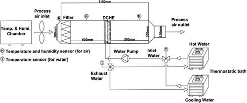
For the dynamic experiments, the desiccant material that illustrates superior performance in the static experiments was coated on a fin-and-tube heat exchanger. The desiccant coating was further applied on the aluminum fins and copper tubes by means of spray coating as described earlier in the static experiment section. The aluminum fins and copper tubes were further assembled and fitted within the air tunnel for the subsequent experimentation process (). The overall dimensions of the DCHE are 340 × 260 × 50 (W × H × D) mm3. The copper tube has a diameter of 9.5 mm and a spacing of 25.4 mm between consecutive copper tubes. The aluminum fins have a thickness of 0.25 mm and a space of 5 mm between them. The test bellows that hold the heat exchanger are made up of acrylic and have dimensions of 1800 × 400 × 300 (L × W × H) mm3. The air was supplied to the air tunnel through a customized environmental chamber. The supplied air has a constant temperature, humidity and flow rate. Two individual thermostatic baths were utilized to supply cold water and hot water of constant temperature for the process of adsorption and desorption. The airflow to the air tunnel and water flow to the DCHE were maintained at 1.8 m3/min and 2.7 L/min, respectively. Meanwhile the temperature of the cold water flow was maintained at a temperature of 25° C. The performance of the DCHE was evaluated under various operating conditions.
Fig. 1. Schematic illustration of the experimental setup for performance evaluation of the desiccant-coated heat exchanger under dynamic testing conditions.
In the adsorption and desorption processes, the dehumidification capacity ( g/s) of the solid desiccant-coated heat exchanger can be obtained from the mass flow rate of the process air and the humidity ratio difference between the inlet and outlet of the heat exchanger:
(6)
(6)
where
(g/s) is the dehumidification capacity,
and
(kgvap/kgda) are the humidity ratios at the inlet and outlet of the heat exchanger, respectively, and
is the mass flow rate of the process air. The vapor dehumidification or regeneration amounts (
) can be calculated through EquationEquation (7)
(7)
(7) by taking the integral of the dehumidification and regeneration capacity with respect to time (τ):
(7)
(7)
where τ is the time period in the vapor adsorption or desorption process. The vapor sorption or desorption amount of desiccant material per unit area (GA, g/cm2) can be further quantified by dividing the vapor sorption or desorption amounts (Gvap) by the area of fin (Afin):
(8)
(8)
The vapor sorption or desorption ability per unit mass of the desiccant (GD, g/g) can be further determined by dividing vapor sorption or desorption amounts (Gvap) by the mass of the desiccant (Mdes) coated on DCHE,
(9)
(9)
To determine the overall energy efficiency of the DCHE in terms of cooling capacity, the average thermal performance COPth was quantified, which is defined as the ratio of the cooling capacity of process air (Qcool) to the heat exchange of water during an effective dehumidification (Qdeh) and regeneration process (Qreg):
(10)
(10)
where
and
are the mass flow rate of the process air and mass flow rate of the water supplied to the DCHE in the dehumidification and regeneration processes, respectively, in kg/s, ΔH represents the difference in enthalpies of the process before and after the DCHE, respectively, in kJ/kg, and Cp is the specific heat of the supplied water at a constant pressure in kJ/kg K.
and
are the temperature differences between the supplied water and exhausted water from the DCHE in the dehumidification and regeneration processes, respectively.
and
are the time periods for the dehumidification and regeneration process. The specific moisture extraction rate (SMER) is used to evaluate the overall energy efficiency of the DCHE in terms of the vapor adsorption amount, which is quantified by the ratio of the total vapor adsorption amount to the total power consumption in the dehumidification process:
(11)
(11)
System uncertainties
Taking into account the uncertainties of the instruments, the system uncertainties for this study were quantified (Li et al. Citation2020; Panigrahi et al. Citation2020). Based on the percentage of error for each individual instrument listed in , the individual uncertainties for mass flow rate of the process air ( vapor adsorption or desorption amounts (Gvap), moisture adsorption or desorption capacity (
), cooling capacity of air (Qcool), specific moisture extraction rate (SMER), average thermal performance (COPth) were quantified within the range of ±0.21%, ±1.16%, ±2.57%, ±1.16%, ±2.68% and ±2.41% respectively.
Table 1. Major equipment lists for the experimental setup.
Results and discussions
Surface area properties of MOF-A520 and Sorbead R
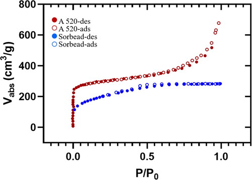
In this study, the surface area and porosity of desiccant material MOF-A520 was quantified using Brunauer-Emmett-Teller (BET) analysis through surface characterization analyzer (3Flex, Micromeritics Instrument corp., Norcross, USA). The nitrogen adsorption amount and the specific surface area of the materials were measured under different relative pressures. After BET analysis of MOF-A520, the results show that when the relative pressure reaches a saturated pressure of one, the adsorption capacity reaches the maximum value of approximately 677 cm3/g, and its specific surface area reaches 884.28 m2/g. The adsorption and desorption curves are quite similar, and the hysteresis loop is not apparent (). This finding corroborates earlier findings that MOFs exhibit a high surface area (Thomas-Hillman et al. Citation2018). Due to the presence of metal ions in MOF molecules, nodes are formed, which facilitate the binding of the arms of the linkers, thereby creating cage-like structures and hollow structures of extremely large internal surfaces (Lu et al. Citation2014; Yao et al. Citation2022).Compared to MOF-A520, the adsorption capacity of Sorbead R only reaches a maximum value of 282.7 cm3/g. Considering the similarity in the particle size, similar weight of coating (see ESI Figure S1) between both the tested desiccants, the overall performance of the desiccant can be directly correlated to its material characteristics.
Fig. 2. BET analysis of MOF (A520) and Sorbead R to quantify the surface area and porosity of the desiccant materials.
Adsorption capacity in static experiments under different environmental conditions
The static adsorption capacities () of the two desiccants, Sorbead R and MOF-A520, were investigated at temperatures of 25 °C and 30 °C and relative humidities of 60% RH, 70% RH and 80% RH, respectively. The moisture adsorption capacities of the two materials were analyzed after completing the heating process of the desiccants for one hour to remove all water content inside the desiccants. shows the static adsorption ability (
) curves of Sorbead R and MOF-A520 under various environmental conditions. The adsorption ability (
) and moisture adsorption capacity (
) were further quantified. The physical adsorption mechanisms of the two desiccant materials both utilize the van der Waals force of the pore inner walls to capture moisture molecules in the air to achieve dehumidification effects. From the moisture adsorption curves in , it was observed that the adsorption abilities of the two materials gradually increase with respect to adsorption time and almost approach saturated values after two hours of adsorption time under the operated environmental conditions. However, for MOF-A520 under environmental relative humidities of 70% and 80% at a temperature of 30 °C, the adsorption abilities do not yet attain saturated states. With increasing relative humidity from 60% RH to 80% RH under the same environmental temperature, the final adsorption abilities of the two desiccants increase as well due to higher vapor pressure in the air at higher relative humidity environmental conditions.
Fig. 3. Adsorption ability curves under environmental temperatures of 25 °C and 30 °C and relative humidity varying from 60% RH to 80% RH for (A) Sorbead R and (B) MOF-A520.
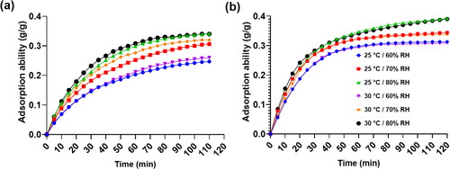
shows the comparison of final adsorption ability using Sorbead R and MOF-A520 as desiccant. It can be seen that after 2-hour water adsorption, the final adsorption ability of MOF-A520 (0.390 g/g) was higher than that of Sorbead R (0.340 g/g) under the environmental temperature of 30 °C and relative humidity of 80% RH. This is because MOF-A520 possesses higher porosity and surface area of 884.28 m2/g that tends to capture more moisture molecules from air. For the final adsorption ability at environmental temperature of 30 °C, with increasing relative humidity from 60% RH to 80% RH, Sorbead R and MOF-A520 increased from 0.260 g/g to 0.340 g/g and 0.309 g/g to 0.390 g/g, respectively. The final adsorption ability of the two desiccants is mainly affected by changes in environmental relative humidity, while the influence of environmental temperature on adsorption ability is comparatively less. From the adsorption ability curve for MOF-A520, when the ambient temperature is 25 °C/30 °C and the relative humidity is 80%RH, the adsorption ability did not reach saturation state in 2 hours adsorption. The adsorption ability can be greater than 0.4 g/g in 3 hours. Elsaid et al. reported that the maximum adsorption ability of silica gel B, silica gel 3 A and silica gel RD were 0.4 g/g, 0.35 g/g and 0.37 g/g, respectively, under the environmental temperature and pressure respectively ranging from 55 °C to 85 °C and 1 kPa to 3.5 kPa (Elsaid and Ahmed Citation2021). Even with the comparison with the adsorption ability of the improved silica gels (i.e. silica gel B, silica gel 3 A, and silica gel RD), MOF-A520 presents relatively better performance in adsorption ability.
Table 2. Static adsorption ability of Sorbead R and MOF-A520 after 2 hours of adsorption under different environmental conditions.
illustrates the adsorption capacity curves of MOF-A520 and Sorbead R under different environmental temperatures and relative humidity conditions. For the two desiccant materials, the maximum adsorption capacities both occur at the beginning adsorption time interval of 5 minutes. With the elapsing adsorption time, the adsorption capacity gradually declines, and the adsorption capacities of the two materials almost approach small values after 2 hours of absorption time. indicates the maximum adsorption capacities of the two desiccants under different environmental conditions. Similarly, with the increase in the environmental humidity and environmental temperature, the maximum adsorption capacities of the two materials also rise due to greater adsorption abilities under higher environmental temperature and relative humidity conditions. Considering the environmental temperature and humidity effects on the maximum adsorption capacity of the two materials, the relative humidity effect on the adsorption capacity is more apparent in comparison to the environmental temperature effect. It was further observed that MOF-A520 has a larger adsorption capability compared to Sorbead R for all the operating conditions. This improvement in the adsorption capacity attributed due to the superior material morphology of MOF-A520 materials. The findings of this study are in agreement with earlier findings (Zhou, Long, and Yaghi Citation2012; Zu, Cui, and Qin Citation2019) showing MOF desiccants outperform traditional desiccants due to their large surface areas, tunable internal surface properties, and small pores. Having a higher sorption rate means that cooling systems can be smaller, more efficient, and economically viable.
Fig. 4. Adsorption capacities under environmental temperatures of 25 °C and 30 °C and relative humidity varying from 60% RH to 80% RH for (A) Sorbead R and (B) MOF-A520.
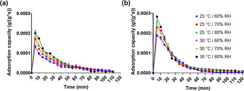
Table 3. Maximum static adsorption capacities () of the two desiccants under different environmental conditions.
Regeneration temperature effect on static desorption capacity
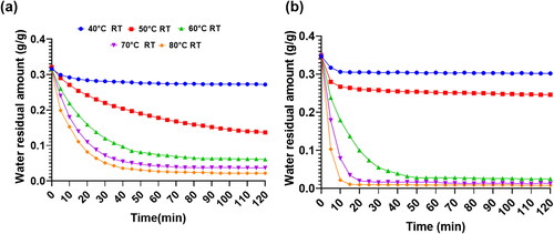
The saturated desiccant materials of MOF-A520 and Sorbead R were placed in heaters with different heating temperatures to conduct desorption experiments in order to understand the desorption characteristics of the two materials under different environmental conditions and different heating regeneration temperatures. illustrates the total residual masses inside the desiccants in the desorption process at an environmental temperature of 30 °C and a relative humidity of 70% RH. The total residual mass consists of the masses of the desiccant and the water content inside the desiccants. From the total residual mass curves, the residual mass inside the materials gradually declines with increasing desorption time from similar initial mass states due to desorption of water content inside the desiccants. Moreover, the higher the regeneration temperature is, the lower the water residual mass contained inside the materials and the lower the total residual mass. For Sorbead R, only when the regeneration temperatures are greater than 70 °C and desorption times are longer than 60 minutes, then only the final total residual amount could be less than 0.05 g/g. However, for MOF-A520, when the regeneration temperatures are greater than 60 °C, the final total residual amount can be less than 0.05 g/g. In particular, when the regeneration temperatures are greater than 70 °C, the required desorption time to attain steady state can be within 20 minutes. The MOF-A520 was completely regenerated at a temperature higher than 60 °C and the dehumidification performance for experiments conducted at the regeneration temperature of 70–80 °C are similar. Due to the lower elapsed time of regeneration temperatures of 70 °C, it can be considered suitable for optimization of heat exchanger performance.
Fig. 5. Total residual mass inside desiccants during the desorption process at an environmental temperature of 30 °C and a relative humidity of 70% RH for (A) Sorbead R and (B) MOF-A520 at different regeneration temperature (RT) settings.
shows the final desorption residual amount per unit mass of Sorbead R and MOF-A520 under different environmental conditions. For both desiccants, with the increase in the regeneration temperature and under the same environmental conditions, the final residual amount per unit mass (RESM) after 2 hours of desorption time gradually decreases due to a greater vapor pressure difference between the surface of the desiccants and the environmental air. Moreover, with the increase in the relative humidity and under the same environmental temperature and regeneration temperature, the RESM gradually increases due to the greater initial saturated absorption vapor amount inside the desiccants under high environmental relative humidity conditions before the desorption process. Similarly, with the increase in the environmental temperature and under the same environmental relative humidity and regeneration temperature, RESM gradually rises due to the greater initial saturated vapor absorption amount under high environmental temperature conditions. Comparing the desorption abilities of the two desiccants under the same operating conditions, the RESM of MOF-A520 is always less than the RESM of Sorbead R because of the greater initial saturated vapor absorption amount inside MOF-A520 and less required regeneration energy for MOF-A520. In particular, when Sorbead R is at an environmental temperature of 30 °C and relative humidity of 60% RH, 70% RH and 80% RH, after a 2-hour desorption time with a regeneration temperature of 80 °C, the RESM values are 0.018 g/g, 0.022 g/g and 0.021 g/g, respectively. However, the RESM values of MOF-A520 can attain lower values of 0.008 g/g, 0.008 g/g and 0.011 g/g under the same environmental conditions and regeneration temperatures.
Table 4. Final residual amount per unit mass of MOF-A520 and Sorbead R with different regeneration temperatures under different environmental conditions.
indicates the water removal percentage (WRP) of MOF A520 and Sorbead R in the desorption process under different environmental conditions and regeneration temperatures. From the tables, it was observed that the WRP values of the two desiccants increase with corresponding to the increase in the regeneration temperature. For Sorbead R, when the regeneration temperature is greater than 60 °C, the WRP can be greater than 80% for all environmental conditions. Further increment of regeneration temperature to 80 °C, the WRP can be further boosted to above 90% for all environmental conditions. However, for MOF-A520, when the regeneration temperature is above 60 °C, the WRP is significantly boosted and can reach above 90%, indicating that the required lowest regeneration temperature of MOF-A520 is less than that of Sorbead R by a margin of 20 °C. In particular, the condensation temperature of the general commercial heat pump is approximately 60 °C, which means that MOF-520A is a suitable desiccant candidate for a desiccant-coated heat exchanger (DCHE) system integrated with a general heat pump for regeneration.
Table 5. Water removal percentage of MOF-A520 and Sorbead R with different regeneration temperatures under different environmental conditions.
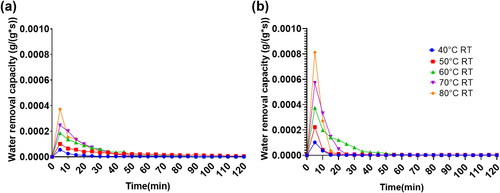
illustrates the water removal capacity curves of MOF-A520 and Sorbead R in the desorption process with elapsed desorption time. The water removal capacity (WRCA) and maximum desorption capacity per unit gram of desiccant were quantified and depicted in and . The whole desorption time is composed of several time steps, and the time step of each time interval is 5 minutes in this study. From the WRCA curves of MOF-A520 and Sorbead R in , for the two desiccant materials, the maximum WRCA value occurs at the beginning desorption time step. With the elapse in desorption time, the WRCA gradually declines, and WRCA values of the two materials almost approach a small value after 2 hours of desorption time. With a greater regeneration temperature, the initial greater WRCA value can be attained. Under the same environmental conditions and regeneration temperature, the initial WRCA value of MOF-A520 is greater than the initial WRCA value of Sorbead R, and the required time to attain the final steady state for MOF-A520 is shorter than the required time to attain the final steady state of Sorbead R. In this study, the steady state is determined when the WRCA value is less than This improved moisture release kinetics of MOF materials might be possible due to its unique molecular arrangement (Kalmutzki, Diercks, and Yaghi Citation2018).
Fig. 6. Water removal capacity under an environmental temperature of 30 °C and a relative humidity of 70% RH for (A) Sorbead R and (B) MOF-A520.
The required desorption time to attain steady state for MOF-A520 and Sorbead R under different environmental conditions and regenerations were quantified (ESI Table S1). For the two desiccants, while the regeneration temperature is less than 60 °C, the vapor pressures on the surface of the desiccants are unable to maintain a stable vapor pressure difference between the environmental air and the surface of the desiccants, causing the unreachable desorption steady state for the two desiccants when the regeneration is below 60 °C. It was observed that the required desorption time for steady state gradually decreases with the rise in regeneration temperature. The environmental temperature and relative humidity effects on the required desorption time are inconspicuous. With a regeneration temperature of 80 °C, the required desorption time for the steady state of Sorbead R is approximately 45 min to 60 min, which is twofold longer than the required desorption time for MOF-A520, which is approximately 20 min to 25 min. For requirements of WRP above 90% and attaining desorption steady state, the lowest regeneration temperature of 60 °C and desorption time of 45 min to 60 min are required for MOF-A520. However, for the same requirements, the lowest regeneration temperature of 80 °C and desorption time of 50 min to 60 min are necessary for Sorbead R. Therefore, in the desorption process, the water content in MOF-A520 can be effectively removed with a relatively low regeneration temperature and shorter required desorption time. This result indicates that MOF-A520 is an excellent desiccant material in practical applications for process air dehumidification ().
Table 6. Maximum desorption capacity per unit gram of MOF-A520 and Sorbead R under different environmental conditions and regeneration temperatures.
Dynamic performance of desiccant coated heat exchanger with MOF-A520
In this study, dynamic operational experiments were carried out by coating MOF-A520 desiccant onto a contemporary fin-and-tube heat exchanger (DCHE) to investigate the performance and corresponding characteristics of the unit under specific operating condition. The dehumidification and regeneration processes were carried out by a 1.8 m3/min process air with the temperature of 25 °C and 30 °C, and the relative humidity of 60%RH, 70%RH, and 80%RH, respectively. Before the dynamic operational experiments, the stability of the temperature and relative humidity of process air was verified. A data logger was used to record and confirm the temperature and humidity values of the process air before the DCHE and after DCHE. A water tank provided supply water with constant temperature of 25 °C to remove the adsorption heat from DCHE during the dehumidification process. The time for dehumidification process was 30 minutes. High temperature water at 40 °C, 50 °C, 60 °C, 70 °C and 80 °C, respectively, was then supplied to DCHE for regeneration process. The time for dehumidification and regeneration processes was 30 minutes individually. The flow rates of cold water and hot water provided from the water tank used in the experiments were both 2.7 L/min.
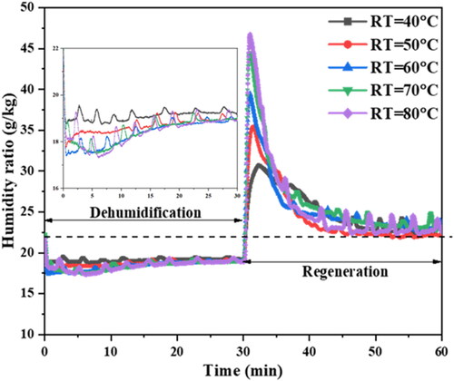
shows the dynamic curves of the humidity ratio of the process air behind the DCHE during the dehumidification process and the regeneration process under the process air supply temperature of 30 °C and the relative humidity of 80% RH. At the beginning of the dehumidification process, the humidity ratio of the process air behind the DCHE is approximately 22.4 g/kg. With the progress of the dehumidification time, the humidity ratio of the process air decreases rapidly and then remains at a certain humidity ratio until the whole dehumidification process is completed. After the 30-minute dehumidification process, hot water with different temperatures was introduced into the DCHE to switch to the regeneration process. In the initial stage of the regeneration process, because the desiccant on the DCHE is heated by the introduction of hot water, the partial vapor pressure on the surface of the desiccant is greater than the partial vapor pressure in the process air, causing a sudden rise in the humidity ratio behind the DCHE. As the regeneration time progresses, the humidity ratio of the process air gradually decreases until the entire regeneration process is completed. At the end of the regeneration process, the humidity ratio of the process air almost returns to the initial humidity ratio of 22.4 g/kg in the dehumidification process. With the rise in the regeneration temperature, the maximum humidity ratio at the initial stage of the regeneration process is greater due to the greater vapor difference between the desiccant surface and the process air.
Fig. 7. Humidity ratio of the process air behind the DCHE in dynamic operation under the process air supply temperature and the relative humidity of 30 °C and 80%RH with different regeneration temperatures. The inset picture highlights the dehumidification curve for each tested regeneration temperature.
indicates the corresponding characteristics of the DCHE with MOF-A520 in dynamic operations under different process air conditions and regeneration temperatures. The vapor absorption amount in the dehumidification process and water desorption amount by the MOF-A520-coated DCHE increases with the increase in the relative humidity of the process air and regeneration temperature. Gvap, GA, and GD denote the total absorption vapor amounts, ratio of absorption vapor amounts per unit contact area of fins and vapor absorption amounts per unit mass of MOF-A520. Under a process air temperature of 30 °C, a relative humidity of 80% RH and a regeneration temperature of 80 °C, Gvap, GA and GD attained maximum values of 239.96 g, 0.0525 g/cm2 and 0.676 g/g during the regeneration process, respectively. The deviation percentages between the vapor adsorption amount and water desorption amount are less than 11%. further illustrates the corresponding specific moisture extraction ratio (SMER) values of the DCHE with MOF-A520 in dynamic operation under different process air environmental conditions and regeneration temperatures. The SMER value increases with the process air relative humidity under the same process air temperature and regeneration temperature due to the greater vapor adsorption amount under higher process air relative humidity conditions. Similarly, the SMER values increase with the process air temperature under the same process air relative humidity and regeneration temperature. However, under the same process air environmental conditions and with the rise in the regeneration temperature, the SMER value gradually decreases. Although a greater vapor adsorption amount can be obtained in the dehumidification process with a higher regeneration temperature, the required energy consumption rises proportionally. However, with the rise in regeneration temperature, the increase in vapor adsorption amount is less than the rise in required energy consumption, resulting the reduction in SMER value corresponding to the increase in the regeneration temperature. For MOF-A520, with a regeneration temperature of 60 °C, the water removal percentage can reach 90%, and the required desorption time is approximately 20 minutes to attain the final steady state. Considering the above characteristics and thermal coefficient of performance in dynamic operation, a regeneration temperature of 60 °C for MOF-A520 is suggested for further operations.
Table 7. Corresponding characteristics of the DCHE with MOF-A520 in dynamic operations under different process air humidity conditions and regeneration temperatures with a process air temperature of 25 °C and 30 °C. Gvap, GA, and GD denote the total vapor absorption vapor amounts, ratio of absorption vapor amounts per unit contact area of fins and vapor absorption amounts per unit mass of MOF-A520. The DEH and REG processes denote the dehumidification and regeneration processes, respectively.
Table 8. The corresponding specific moisture extraction ratio (SMER) values and thermal coefficient of performance (COPth) of the DCHE with MOF-A520 in dynamic operation under different process air environmental conditions and regeneration temperatures.
illustrates the corresponding average cooling capacity, required average regeneration power and average total power in a dehumidification process and a regeneration process under the supply process air temperature of 30 °C and relative humidity of 80%. The average cooling capacity ( indicates the average energy transfer rate in the dehumidification process between the process air and the cooling water inside the copper tube of the DCHE, including sensible and latent heat transfer. The required average regeneration power in the regeneration process (
indicates the average required power consumption in the regeneration process between the process air and the hot water inside the copper tube of the DCHE. Similarly, the required average dehumidification power (
indicates the average heat transfer rate in the dehumidification process between the process air and the cooling water inside the copper tube of the DCHE. The required average total power consumption (
includes the heat transfer gain of the cooling water in the dehumidification process and the required power in the regeneration process.
Fig. 8. Average cooling capacity in the dehumidification process, the required average regeneration power in the regeneration process and the total power consumption in dehumidification and regeneration processes with different regeneration temperatures under the (A) process air temperature of 25 °C and relative humidity of 80%. (B) Process air temperature of 30 °C and relative humidity 80%.
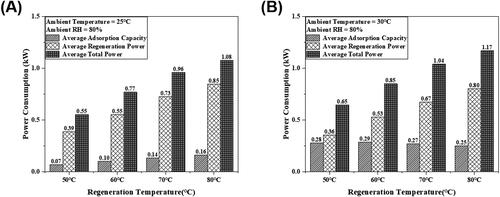
As illustrated in , the average cooling capacity, average regeneration power and total average power consumption of the DCHE gradually increase with the increase in the regeneration temperature. The maximum power consumption of the DCHE within an operational cycle comes from the average regeneration power during the regeneration process, which accounts for approximately 75% of the total average power consumption in a whole operational cycle. In particular, with the increase in the regeneration temperature, the percentage of the average generation power increases due to a greater heat transfer rate from the hot water to the process air with higher regeneration temperatures. Moreover, with the increase in the regeneration temperature, the average cooling capacity of the DCHE gradually increases. In the dehumidification process, the adsorption of vapor in the process air by the desiccant (MOF-A520) led to the decrease of humidity ratio of DCHE and the increase in the adsorption heat to the process air. The humidity ratio reduction of the process air causes the latent heat loss of the process air after passing through the DCHE. However, the adsorption heat released to the process air leads to the sensitive heat gain of the process air after passing through the DCHE. The latent heat loss of the process air is greater than the sensible heat gain of the process air in the dehumidification process and gradually increases with increasing regeneration temperature, resulting in an increase in the average cooling capacity with a rise in the regeneration temperature. In that case, with the rise in the regeneration temperature, the increment in the cooling capacity (7.6%) is greater than the increment in the total average power (5.9%). As illustrated in , the thermal COPth gradually increases with increasing regeneration temperature.
illustrates the DCHE performance under the 30 °C and 80%RH process air with various regeneration temperatures. The required regeneration power and the total consuming power both gradually increases corresponding to the increase in the regeneration temperature. The maximum consuming power came from the regeneration power, which is about 62% of the total consumed power in one operational cycle. At a process air temperature of 30 °C, more vapor is absorbed by the MOF-A520 desiccant in comparison with the vapor absorbed at a process air temperature of 25 °C, leading to greater heat gain from the cooling water. Thus, the proportion of the regeneration power under 30 °C process air temperature was less than that under 25 °C process air. The average cooling capacity of the DCHE declined with the rise in the regeneration temperature, inducing more vapor adsorbed by MOF-A520 and greater heat released to the process air under higher relative humidity condition. This phenomenon resulted in the cooling capacity of DCHE during the dehumidification process declined slightly with increase in relative humidity. As illustrated in , the greater increment in the total consuming power causes the gradual reduction of thermal COPth with the rise in regeneration temperature at the process air temperature of 30 °C.
Conclusions
This study investigates the performance of a solid desiccant material, namely, MOF-A520, under various operational conditions. The efficacy of the material was tested and compared with the efficacy of a traditional Sorbead R-type solid desiccant by means of static experimentation. Desiccants with better dehumidification were then selected and coated on a fin-tube heat exchanger (DCHE), and their thermal and dehumidification performances were evaluated within the controlled environment of an air tunnel.
The following conclusions are derived from the study:
With a temperature of 30 °C and a relative humidity of 80% RH, the final adsorption capacities of MOF(A520) and Sorbead R after 2 hours were 0.392 g/g and 0.341 g/g, respectively, highlighting a 15% higher adsorption capacity for the MOF(A520)-type desiccant. A similar trend in the maximum adsorption rate was also noticed. The superior adsorption capacity and adsorption rate are due to the small particle size, high specific surface area and high porosity of the MOF (A520)-type desiccant.
With an ambient temperature of 30 °C and a relative humidity of 80% RH, the initial maximum desorption rates of MOF-A520 and Sorbead R are 9.89 × 10⁻⁴ g/(g*s) and 3.74 × 10⁻⁴ g/(g*s), respectively, highlighting the superior desorption ability of MOF-A520 over Sorbead R. We inferred that the high specific surface area and high porosity allow MOF-A520 to have a greater initial desorption rate in a short time span. With a regeneration temperature setting of 60 °C, MOF-A520 can remove approximately 90% of the water, which is at least 10% more than Sorbead R.
In dynamic operations, the vapor adsorption amount in the dehumidification process and water desorption amount by the MOF-A520-coated DCHE increases with the increase in the relative humidity of the process air and regeneration temperature under the same process air temperature. Under the process air temperature of 30 °C, relative humidity of 80% RH and regeneration temperature of 80 °C, Gvap, GA and GD attained maximum values of 239.96 g, 0.052 g/cm2 and 0.676 g/g, respectively, during the regeneration process.
The SMER value increases with the increase in the process air relative humidity and the process air temperature under the same regeneration temperature due to a greater amount of vapor adsorption. However, under the same process air environmental conditions and with the rise in the regeneration temperature, the SMER value gradually decreases because the increase in vapor absorption amount is comparatively less than the rise in required energy consumption.
Considering the sorbent characteristics in static test and thermal coefficient of performance in dynamic operation, MOF-520A desiccant possessed characteristics of excellent adsorption ability, lower regeneration temperature (60 °C) and shorter desorption time (20 minutes), indicating that MOF-A520 is an excellent desiccant material for air dehumidification in air conditioning applications.
| Abbreviation | ||
| COPth | = | Average thermal coefficient of performance |
| DCHEs | = | Desiccant coated Heat Exchanger |
| GPHEs | = | Granular packed heat exchangers |
| MOF | = | Metal organic frame work |
| RESM | = | Residual amount per unit mass of desiccant |
| RT | = | Regeneration temperature |
| WRCA | = | Water removal capacity |
| WRP | = | Water removal percentage |
| SDBD | = | Solid desiccant-based dehumidification |
| SMERth | = | Average thermal performance |
| Nomenclature | ||
| = | Adsorption ability of the desiccant, g/g | |
| = | Adsorption abilities of the desiccant in the (n + 1)th interval, g/g | |
| = | Adsorption abilities of the desiccant in the nth interval, g/g | |
| Afin | = | Area of fin, mm2 |
| Cp | = | Specific heat of the supplied water at a constant pressure, kJ/kg K |
| = | Dehumidification capacity of the DCHE, g/s | |
| = | Vapor dehumidification or regeneration amounts, g | |
| GA | = | Vapor sorption or desorption amount of desiccant material per unit area, g/cm2 |
| GD | = | The vapor sorption or desorption ability per unit mass of the desiccant, g/g |
| = | Weight of desiccant and adsorption water in the nth time interval, g | |
| = | Initial desiccant weight in drying state, g | |
| = | Static moisture adsorption capacity, g/g.s | |
| Mw,res | = | Residual water amount after 2 hours desorption time, g |
| = | Residual amounts at the end of the nth time interval, g | |
| = | Residual amounts at the end of the (n + 1)th time interval, g | |
| Mdes | = | Mass of the desiccant coated on DCHE, g |
| Mw,sat | = | Initial saturated water content inside the desiccants before desorption process, g |
| = | Mass flow rate of the process air, kg | |
| = | Mass flow rate of the supplied water to DCHE, kg | |
| Qcool | = |
|
| Qdeh | = |
|
| Qreg | = | Heat exchange of water during an regeneration process, |
| = | Average regeneration power during regeneration process, | |
| = | Average dehumidification power, | |
| = | Average total power consumption, | |
| = | Average regeneration power during regeneration process, | |
| Greek symbols | ||
| ΔH | = | The difference in enthalpies of the process before and after DCHE, kJ/kg |
| = | Time step | |
| = | The temperature differences between the supplied water and exhausted water from the DCHE in the dehumidification process | |
| = | The temperature differences between the supplied water and exhausted water from the DCHE in the regeneration process | |
| = | The humidity ratios at inlet of DCHE, | |
| = | The humidity ratios at outlet of DCHE, | |
| = | The time periods for the dehumidification process | |
| = |
| |
| τ | = | Time |
Disclosure statement
No potential conflict of interest was reported by the author(s).
Additional information
Funding
References
- Albaik, I., M. B. Elsheniti, R. Al-Dadah, S. Mahmoud, and İ. Solmaz. 2022. Numerical and experimental investigation of multiple heat exchanger modules in cooling and desalination adsorption system using metal organic framework. Energy Conversion and Management 251:114934.
- Arif, M. N., A. Waqas, F. A. Butt, M. Mahmood, A. H. Khoja, M. Ali, K. Ullah, M. Mujtaba, and M. J. A. E. J. Kalam. 2022. Techno-economic assessment of solar water heating systems for sustainable tourism in northern Pakistan. Alexandria Engineering Journal 61 (7):5485–99.
- Aziz, A. N., S. Mahmoud, R. Al-Dadah, M. A. A. Ismail, and M. K. Mesfer. 2022. Numerical and experimental investigation of desiccant cooling system using metal organic framework materials. Applied Thermal Engineering 215:118940.
- Chang, C.-C., W.-J. Luo, C.-W. Lu, Y.-S. ChenG, B.-Y. Tsai, and Z.-H. Lin. 2017. Effects of process air conditions and switching cycle period on dehumidification performance of desiccant-coated heat exchangers. Science and Technology for the Built Environment 23 (1):81–90.
- Chaudhary, G. Q., M. Ali, M. Ashiq, H. M. Ali, and K. P. J. T. S. Amber. 2019. Experimental and model based performance investigation of a solid desiccant wheel dehumidifier in subtropical climate. Part B 23 (2):975–88. ),
- Chen, L., C. J. M. He, and M. Materials. 2020. Experimental investigation of the dehumidification performance of a metal-organic framework MIL-101 (Cr)/ceramic fibre paper for use as a desiccant wheel. Microporous and Mesoporous Materials 305:110378.
- Chen, Z., P. Li, X. Zhang, P. Li, M. C. Wasson, T. Islamoglu, J. F. Stoddart, and O. K. Farha. 2019. Reticular access to highly porous acs-MOFs with rigid trigonal prismatic linkers for water sorption. Journal of the American Chemical Society 141 (7):2900–5. 10.1021/jacs.8b13710
- Cui, W. G., T. L. Hu, and X. H. J. A. M. Bu. 2020. Metal–organic framework materials for the separation and purification of light hydrocarbons. Advanced Materials 32 (3):1806445.
- De Lange, M. F., K. J. Verouden, T. J. Vlugt, J. Gascon, and F. J. C. r. Kapteijn. 2015. Adsorption-driven heat pumps: The potential of metal-organic frameworks. Chemical Reviews 115 (22):12205–50.
- Elavarasan, R. M., G. Shafiullah, S. Padmanaban, N. M. Kumar, A. Annam, A. M. Vetrichelvan, L. Mihet-Popa, and J. B. J. I. A. Holm-Nielsen. 2020. A comprehensive review on renewable energy development, challenges, and policies of leading Indian states with an international perspective. IEEE Access 8:74432–57.
- Elsaid, A. M., and M. S. Ahmed. 2021. Indoor air quality strategies for air-conditioning and ventilation systems with the spread of the global coronavirus (COVID-19) epidemic: Improvements and recommendations. Environmental Research 199:111314. 10.1016/j.envres.2021.111314
- Fekadu, G., S. J. R. Subudhi, and S. E. Reviews. 2018. Renewable energy for liquid desiccants air conditioning system: A review. Renewable and Sustainable Energy Reviews 93:364–79.
- Fong, K., C. K. Lee, T. T. Chow, and A. J. A. T. E. Fong. 2011. Investigation on solar hybrid desiccant cooling system for commercial premises with high latent cooling load in subtropical Hong Kong. Applied Thermal Engineering 31 (16):3393–401.
- Gao, H., C. Koch, and Y. J. A. e. Wu. 2019. Building information modelling based building energy modelling: A review. Applied Energy 238:320–43.
- Ge, L., T. Ge, and R. Wang. 2022. Facile synthesis of Al-based MOF and its applications in desiccant coated heat exchangers. Renewable and Sustainable Energy Reviews 157:112015.
- Gökpinar, S., S.-J. Ernst, E. Hastürk, M. Möllers, I. El Aita, R. Wiedey, N. Tannert, S. Nießing, S. Abdpour, and A. Schmitz. 2019. Air-con metal–organic frameworks in binder composites for water adsorption heat transformation systems. Industrial & Engineering Chemistry Research 58 (47):21493–503.
- Golubovic, M. N., H. M. Hettiarachchi, and W. M. Worek. 2007. Evaluation of rotary dehumidifier performance with and without heated purge. International Communications in Heat and Mass Transfer 34 (7):785–95.
- Hou, P., K. Zu, M. Qin, and S. J. B. Cui. 2021. A novel metal-organic frameworks based humidity pump for indoor moisture control. Building and Environment 187:107396.
- Kalmutzki, M. J., C. S. Diercks, and O. M. Yaghi. 2018. Metal–organic frameworks for water harvesting from air. Advanced Materials 30 (37):1704304.
- Kannan, V. S., T. Arjunan, and S. Vijayan. 2021. Drying characteristics of mint leaves (Mentha arvensis) dried in a solid desiccant dehumidifier system. Journal of Food Science and Technology 58 (2):777–86.
- Karmakar, A., V. Prabakaran, D. Zhao, and K. J. Chua. 2020. A review of metal-organic frameworks (MOFs) as energy-efficient desiccants for adsorption driven heat-transformation applications. Applied Energy 269:115070.
- Lee, J.-G., K. J. Bae, and O. K. Kwon. 2021. Experimental investigation of the solid desiccant dehumidification system with metal organic frameworks. International Journal of Refrigeration 130:179–86.
- Li, A., K. Thu, A. B. Ismail, M. W. Shahzad, and K. C. Ng. 2016. Performance of adsorbent-embedded heat exchangers using binder-coating method. International Journal of Heat and Mass Transfer 92:149–57.
- Li, K.-Y., W.-J. Luo, B.-Y. Tsai, and Y.-D. Kuan. 2020. Performance analysis of two-stage solid desiccant densely coated heat exchangers. Sustainability 12 (18):7357.
- Liu, H., H. Yang, and R. J. A. E. Qi. 2020. A review of electrically driven dehumidification technology for air-conditioning systems. Applied Energy 279:115863.
- Liu, Z., C. Cheng, J. Han, Z. Zhao, and X. Qi. 2022. Experimental evaluation of the dehumidification performance of a metal organic framework desiccant wheel. International Journal of Refrigeration 133:157–64.
- Lu, W., Z. Wei, Z.-Y. Gu, T.-F. Liu, J. Park, J. Park, J. Tian, M. Zhang, Q. Zhang, T. Gentle, et al. 2014. Tuning the structure and function of metal–organic frameworks via linker design. Chemical Society Reviews 43 (16):5561–93.
- Luo, W.-J., D. Faridah, F. R. Fasya, Y.-S. Chen, F. H. Mulki, and U. N. Adilah. 2019. Performance enhancement of hybrid solid desiccant cooling systems by integrating solar water collectors in Taiwan. Energies 12 (18):3470.
- Mohseni, M. M., M. Jouyandeh, S. M. Sajadi, A. Hejna, S. Habibzadeh, A. Mohaddespour, N. Rabiee, H. Daneshgar, O. Akhavan, and M. Asadnia. 2022. Metal-organic frameworks (MOF) based heat transfer: A comprehensive review. Chemical Engineering Journal 449:137700.
- Moitra, P., M. Alafeef, K. Dighe, P. Ray, J. Chang, A. Thole, B. Punshon-Smith, M. Tolosa, S. S. Ramamurthy, X. Ge, et al. 2021. Rapid and low-cost sampling for detection of airborne SARS-CoV-2 in dehumidifier condensate. Biotechnology and Bioengineering 118 (8):3029–36. &. )
- Mostafavi, F., M. Tahsildoost, and Z. J. B. Zomorodian. 2021. Energy efficiency and carbon emission in high-rise buildings: A review (2005–2020). Building and Environment 206:108329.
- Oh, S. J., K. C. Ng, W. Chun, and K. J. E. J. E. Chua. 2017. Evaluation of a dehumidifier with adsorbent coated heat exchangers for tropical climate operations. Energy 137:441–8.
- Okati, V., S. Farsad, and A. J. D. Behzadmehr. 2018. Numerican analysis of an integrated desalination unit using humidification-dehumidification and subsurface condensation processes. Desalination 433:172–85.
- Oladosu, T. L., A. T. Baheta, and A. N. Oumer. 2021. Desiccant solutions, membrane technologies, and regeneration techniques in liquid desiccant air conditioning system. International Journal of Energy Research 45 (6):8420–47.
- Panigrahi, B., Y. S. Chen, W. J. Luo, and H. W. Wang. 2020. Dehumidification effect of polymeric superabsorbent SAP-LiCl composite desiccant-coated heat exchanger with different cyclic switching time. Sustainability 12 (22):9673.
- Scheffran, J., M. Felkers, and R. J. G. E. t S. S. f G. I. Froese. 2020. Economic growth and the global energy demand. In Green energy to sustainability: Strategies for global industries, chapter 1, 1–44. Wiley Online Library.
- Shah, A., H. S. Sankhe, Y. K. Sharma, S. Sankhe, and R. Kale. 2022. Comparative study and analysis of HVAC systems using solid and liquid desiccant dehumidification technology. Proceedings of Fourth International Conference on Inventive Material Science Applications.
- Tatlier, M. 2017. Performances of MOF vs. zeolite coatings in adsorption cooling applications. Applied Thermal Engineering 113:290–7.
- Thomas-Hillman, I., A. Laybourn, C. Dodds, and S. W. Kingman. 2018. Realising the environmental benefits of metal–organic frameworks: Recent advances in microwave synthesis. Journal of Materials Chemistry A 6 (25):11564–81.
- Vivekh, P., D. Bui, M. Islam, K. Zaw, and K. J. A. E. Chua. 2020. Experimental performance and energy efficiency investigation of composite superabsorbent polymer and potassium formate coated heat exchangers. Applied Energy 275:115428.
- Xu, F., Z. Bian, T. Ge, Y. Dai, C. Wang, and S. Kawi. 2019. Analysis on solar energy powered cooling system based on desiccant coated heat exchanger using metal-organic framework. Energy 177:211–21.
- Yao, Y., X. Zhao, G. Chang, X. Yang, and B. Chen. 2022. Hierarchically porous metal–organic frameworks: Synthetic strategies and applications. Small Structures 4 (1):2200187.
- Yoro, K. O., and M. O. Daramola. 2020. CO2 emission sources, greenhouse gases, and the global warming effect. In Advances in carbon capture, chapter 1, 3–28. Woodhead Publishing.
- Yu, Y., S. You, H. Zhang, T. Ye, Y. Wang, S. J. R. Wei, and S. E. Reviews. 2021. A review on available energy saving strategies for heating, ventilation and air conditioning in underground metro stations. Renewable and Sustainable Energy Reviews 141:110788.
- Zhang, J., P. Li, X. Zhang, X. Ma, and B. J. Wang. 2020. Aluminum metal–organic frameworks with photocatalytic antibacterial activity for autonomous indoor humidity control. ACS Applied Materials & Interfaces 12 (41):46057–64.
- Zhang, L., X. Zha, X. Song, and X. J. E. C. Zhang. 2019. Optimization analysis of a hybrid fresh air handling system based on evaporative cooling and condensation dehumidification. Energy Conversion and Management 180:83–93.
- Zhou, H.-C., J. R. Long, and O. M. Yaghi. 2012. Introduction to metal–organic frameworks. Chemical Reviews 112:673–4.
- Zu, K., S. Cui, and M. Qin. 2019. Performance comparison between metal-organic framework (MOFs) and conventional desiccants (silica gel, zeolite) for a novel high temperature cooling system. IOP Conference Series: Materials Science and Engineering 609 (5):052013.