
 ?Mathematical formulae have been encoded as MathML and are displayed in this HTML version using MathJax in order to improve their display. Uncheck the box to turn MathJax off. This feature requires Javascript. Click on a formula to zoom.
Abstract
There have historically been, and still are, problems with water intrusion into new external walls of prefabricated concrete sandwich elements in Sweden to a varying extent. The aim of this study was to obtain documented knowledge and data on driving rain resistance, to provide a basis for improvements and calculations in a common kind of concrete sandwich system with façade components and sealing products. The study included inspections and air pressure difference measurement of façades in the field and driving rain resistance testing of experimental set-ups in a laboratory. Inspection showed that vertical joints between the concrete elements were often significantly too narrow and, at the same time, adhesion loosening of building mastic in these joints was common. TDV-tubes were often incorrectly placed or had a bad incline. Field measurements indicate no pressure equalization, which is also confirmed by lab measurements. Lab results indicated inward leakage at window-wall interface, even without wind pressure, through the TDV-tubes despite a sharp incline, in element joints with a new kind of application of pre-compressed joint sealing tape. The largest leakage flows were of 0.4% of the vertical water flow across a unit width of the façade at the given height.
Introduction
Water penetration in walls with concrete sandwich elements has historically been an issue (Hasselblad & Andersson, Citation1972; Brycke & Svensson Tengberg, Citation2019; Jerling & Schechinger, Citation1983) and there are still problems in new exterior walls in Sweden (Brycke & Svensson Tengberg, Citation2019). In an investigation from 1977, of 56000 apartments, 11% had problems with water leakage through walls with concrete elements (Jerling & Schechinger, Citation1983). The issues described above have caused and increased the risk of moisture-related damages, indoor environmental matters, increased needs for repair and an increased risk of not obtaining energy efficiency.
It has not previously been possible to provide an unambiguous picture of the scope, but the existence of problems is clear (Jerling et al., Citation1988). Leakage areas that generally have been pointed out are joints in concrete elements, cracks in concrete, window connections and balcony connections, according to a recent survey and interviews (Brycke & Svensson Tengberg, Citation2019). However, the exact causes in Sweden have been unclear. Examples of articles on similar topics have been published internationally (Lacasse et al., Citation2009; Kudder & Erdly, Citation1998). In addition, it appears as if there is an application of single line of defense in concrete sandwich walls, which are known to be problematic. Although two-stage sealing is recommended in the literature (Jerling & Schechinger, Citation1983; Straube, Citation2013), the method is uncommon in Sweden. Moreover, it has previously been found that common types of façades with component connections in Sweden are susceptible to water intrusion from wind driven rain (Olsson, Citation2017b). Altogether, the survey and interview study by Brycke & Svensson Tengberg mentioned above led to the initiation of the current study presented in this article.
The aim of this study is to find out the exact causes of water intrusion in precast concrete walls, to provide input to improve solutions and to investigate how façades with sealed joints of concrete elements are made and work. In addition this study aims to produce documented results of deterioration; knowledge and data of wind driven rain resistance of common concrete constructions including new and existing sealing products; and rank the various sealing principles.
Material and methods
The study includes inspections and pressure difference measurements of concrete sandwich walls in the field and driving rain resistance testing of experimental set-ups in a laboratory.
Field study
Inspections
The field study consists of 11 property inspections with multiple buildings. Inspections of façades in the field were conducted through visual inspection and measurement of element length and vertical joint widths that were accessible from ground level. The investigated building sites are located in the southwest of Sweden, in Helsingborg, Lund, Kristianstad, Gothenburg, Borås and Ulricehamn. These building sites were selected due to good geographical location in terms of traveling. They were chosen randomly from a list of two concrete sandwich element manufacturers and more than 60 construction projects.
Concrete sandwich elements consist of two concrete panels, the outer panel is often 70 mm thick and the inner panel is 100 mm thick, with 200 mm thick intermediate insulation, see example in . The insulation is made up of various cellular insulation boards of polyisocyanurate (PIR), phenolic foam (PF), expanded polystyrene (EPS) and mineral wool boards, as shown in .
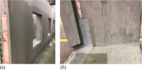
Fig. 1. a) Newly manufactured concrete sandwich element in factory, b) Installed flashing of butyl tape that covers the insulation at the wall below a window opening, as well as external pre-compressed sealing tape on concrete edges.
The inner concrete panel is load bearing and the outer concrete panel is suspended on the inner one with stainless steel/acid-proof connections. The elements are prefabricated in a factory and windows are often installed. In the assembly at the construction site, the elements need to be given a degree of movement, in both the vertical and horizontal axes, mainly due to subsequent and future temperature and moisture fluctuations in the outer concrete panel. The joints on the inside are poured shut with concrete.
Façade joints are made with seals of building mastic as shown in , known as face-sealed joints (FIB, 2014). Behind the building mastic and the backer rod, there is a 15 mm air channel. Neither backer rod nor air channel could be visually inspected in the field due to visual inspection. The common type of sealant (F 25 LM) in Sweden, building mastic, has an applicable movement capability of 25% according to the International Standard (ISO 11600). If this movement is exceeded, there is a risk of cracks and adhesion loosening in the building mastic. There is a “rule of thumb” for inspections of the joint width, B, which can be calculated according to the formula Equation(1)(1)
(1) where l1 and l2 are the lengths of the two adjacent elements, specified in millimeters (Svensk-Byggtjänst, Citation2021b). This formula was used during field inspection.
(1)
(1)
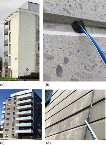
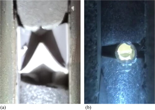
Fig. 2. a) Five-story building in Kungälv, b) Measurement of pressure difference across façade/joint sealing at floor two, c) Eight-story building in Borås, d) Measurement of pressure difference across joint sealing. The measurement hose is mounted via TDV-tube at floor seven.
Joints are to be provided with openings in each joint intersection, and can be made as overlapping joints that are 100 mm vertically or with TDV tubes (T = pressure equalization, D = drainage, V = ventilating opening) as shown in and , which was the only type of opening found in the field study, in order for the air channel to be in contact with outdoor air (Svensk-Byggtjänst, Citation2021a). The tubes should be installed with a 45-degree incline outwards/downwards and so that they protrude at least 3 mm outside the joint/building mastic as shown in and . Openings should also contribute to pressure equalization. TDV tubes are also known as ventilation pipe with drainage (FIB, Citation2017)
Recently, a relatively new kind of joint seal (Farrington et al. 2019), made of pre-compressed joint sealing tape without formal evaluation has begun to be used in Sweden (Svensson Tengberg et al., Citation2021). However, this was not found in the field study apart from window connections.
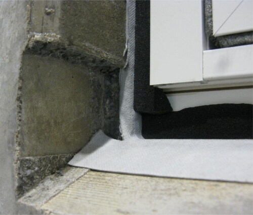
For windows, pre-compressed joint sealing tape is often used in the caulking space between window frame and wall as shown in together with external pre-compressed tape as shown in , between, for example, the aluminum-clad part of wooden windows and concrete edges (at the sides of the window and upper edge). However, this sealing method could not be inspected in the field. Below windows in concrete elements, a second line of defense, flashing with butyl tape is often installed with skirting on the sides by a few decimeters as shown in . In addition, few buildings were found with external sealing of building mastic, sheet metal covering at reveals or sealing strip between windows and concrete edges. In the lab tests, one of the windows had a sheet metal clad reveal as shown in .
Measurements of pressure difference
Pressure equalization has been measured in three buildings, see examples in , over the façade (between outside and back façade, behind joint sealing, as shown in ) that had wind direction more or less toward the façade (to façade normal). Continuous measurements were taken for 1-2 h with a measurement interval of 1 sec (mean of 20 readings). The measurements were carried out with pressure gauges from the manufacturer TEC DG-1000 and DG-700. A mobile weather station was rigged up at a distance between 50 and 80 meters from the buildings and at a height of 2 meters above the ground (Borås and Kungälv) or approximately 2 meters above the building’s roof (Gothenburg). Wind speed and wind direction were measured with a cup anemometer (make/model: Davis Instruments Vantage Pro2). The highest wind speed for 60 s and its direction were recorded as well as average wind speed and wind direction. These measurements were based on measurement every three seconds but only average speed (during 60 s) and the highest value (max wind speed during 60 s) were recorded.
Test walls in lab
Laboratory tests of walls were carried out through driving rain tightness testing according to standard EN 12865 where driving rain was created with water spray and pulsating air pressure (pulse takes 15 s) with five steps and one step last 60 min, 0 Pa, 0-150, 0-300, 0-450 and 0-600 Pa. The wind pressure may be of significance to leakage, which is why pressure differences were also measured over façade and joint sealing. It is estimated that an 40-180 Pa pressure difference corresponds to a wind speed of approximately 8-16 m/s for optimal conditions.
By scaling down (reducing to one third of actual size) the concrete elements in the set-up, multi-story façades with element joints were able to be studied in test rigs of 3 × 3 meters. Sealing of joints between the concrete elements and window and balcony connections was done by experienced manufacturers and joint contractors. Driving rain resistance was studied in two test rounds where the first leakage control was done visually and, prior to the second round, systems for water collection were installed to quantify the leakage flows more precisely. Prior to the third round, some faults were created, based on the adhesion loosening found in the inspections in the field, etc., and leakage flow was measured.
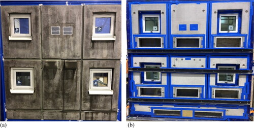
The laboratory experiments consist of two objects/walls from two concrete sandwich element manufacturers. Both test objects (object 1 and object 2) were manufactured from the same drawing and consisted of six scaled-down concrete sandwich elements with a length and height of 1.3 × 1.0 meters. Four of these elements were fitted with a window (the windows were installed at the factory), and one concrete element was fitted with two balconies as shown in . The upper windows were installed against concrete edges and with pre-compressed joint sealing tape in between, as shown in , , and the lower windows without concrete edges as shown in , , and .
Fig. 3. Test object 2, a) external side of concrete sandwich wall directly after the driving rain exposure in rain chamber, b) Internal side of wall with inspection hatches of plexiglass and three horizontal steel beams to keep the elements in place.
When it comes to the balconies, they were not completely through the wall because they were attached to the inner concrete panel as shown in . The vertical element joints and the horizontal element joints in the middle were of the parallel joint type (not fold or tongue and groove) as shown in and cross-section A-A. In addition, there was a seventh concrete element placed at the bottom with a height and width of 0.4 × 3 meters and the joint was of the tongue and groove type. Half the façade, to the left, of the test objects were made with joints of building mastic and TDV tubes as well as an opening of the overlapping joint type with channel dimensions of width 25 x height 15 x length 100 mm as shown in . This overlapping joint was not found in the field study. In object 2, the TDV tubes had a diameter of 10 mm and, in object 1, the tubes had a diameter of 8 mm as well as TUDV tubes with a diameter of 6 mm. TUDV tubes have collecting flanges (U = collecting) as shown in . The second half of the façade was made with joints of pre-compressed sealing tape without openings as shown in and . This type of new sealing was not found in the field study.
Fig. 4. Elevation of test wall (applies to both objects 1 and 2). Vertical wall cross-section at window is shown in A-A and at balcony in B-B.
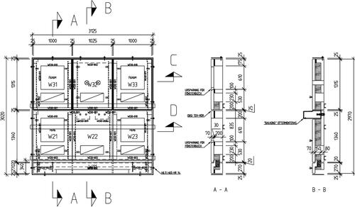
Fig. 5. a) Joint of building mastic at joint intersections and at balcony connection, as well as TDV tubes and TDV opening of overlapping type. b) Pre-compressed joint sealing tape in joint intersections.
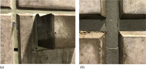
Fig. 6. Object 1. a) TUDV tube seen from the inside. b) new TDV tube without incline seen from the inside during ongoing test 3.
Prior to the second test round, water collection systems were installed to quantify leakage flows more precisely. Channels and hoses were connected together with a collecting tank and were designed as a “closed” system. The collecting tanks were weighed after each pressure step. For example, based on observations in the field, adhesion loosening/slits in vertical joints, hole in pre-compressed joint sealing tape; and tape that was not fully compressed and misaligned with the joint were installed. The size of slits and holes appear in the results chapter, shown in and .
Field results
Inspections
During inspections of façades, adhesion loosening was found in element joints in eight out of 11 buildings even though most of the buildings were relatively newly built as shown in and . Several types of non-conformities were also found as shown in . In general, TDV tubes were misplaced, often above joint intersections and lacked sufficient incline. Cracks were also found in building mastic around TDV tubes as shown in . In some façades, all or part of the TDV tubes or openings were missing. Defects at window-wall interfaces and gaps in pre-compressed sealing tape were found. There were recognizable leaks at exterior metal flashing connections to façades with the risk that water could at least penetrate behind them. In addition, 25 concrete elements with cracks were found across eight buildings as shown in and .
Table 1. Non-conformities upon inspection.
Measured joint width showed that in all buildings, joints were often too narrow as shown in . The average difference from the rule of thumb was that the joint width between the elements was 37% too narrow on average for vertical joints at the time of inspection. This indicates that it is common that the joint width is incorrectly dimensioned.
In addition, adhesion loosening was common as shown in and , in joints of building mastic consistent with the observation that the joints were too narrow as defined by Equationequation (1)(1)
(1) ”.
Table 2. Number of narrow joints of total measured joints and the joint width difference (mean) from the rule of thumb in percent. The longest combination of two panels jointed together.
Measurements of pressure difference
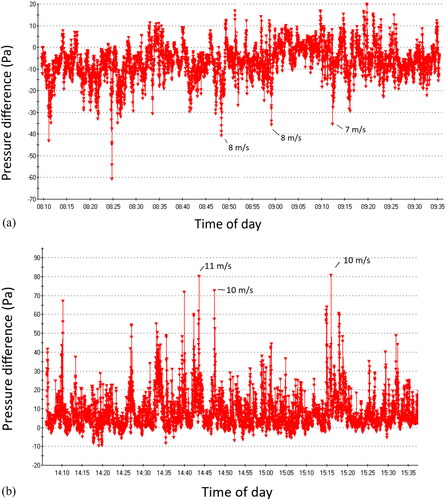
The measurements show pressure differences of 25-40 Pa negative pressure (the reference is outside) in the wall behind the façade/joint sealing at approximate wind gusts speed of 7-8 m/s, as shown in and . The wind direction was more or less perpendicular to the façade in these cases. If the wind direction had been exactly perpendicular to the façades, a slightly larger pressure difference would probably have been measured. A pressure difference of 70-80 Pa, positive pressure in the wall, occurred with a wind gust speed of approximately 10-11 m/s, as shown in . The wind direction was more or less perpendicular to the opposite façade due to wind direction change, which is why a positive pressure difference was measured. In this building, a clear over-pressure inside to the outside could also be noted due to the indoor air ventilation system. These measurements show that the walls behind the façade do not have a pressure-equalizing function (pressure equilibrium).
The measurements show that the wind creates pulsating pressure in the wall and a pulse often lasts about 15 s but sometimes less and sometimes more. The change itself often takes place relatively quickly within one or a few seconds. The pulses in the test method in the laboratory experiments according to EN 12865 last for 15 s and change within a few seconds, which corresponds roughly to what the measurements show in , for example. The laboratory test method appears to be relatively realistic based on these observations.
Laboratory results
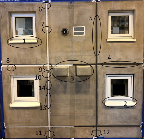
The water load or run-off flow, 189 l/h,m per running meter of façade length on the façade, was quantified. shows where the leakage occurred for test object 2 and for test object 1. The same leakage also appeared in the first round of the tests. Measurement points 1-10 are areas where the leakage occurred and was able to be measured as shown in and . Measurement points 11-12 are leakages of more imprecise origin that may have partly come in from leakage points higher up in the wall. However, leakage was found in TDV tubes at joint intersections just above measurement point 11, which is a minor contribution to the leakage flow at measurement point 11.
The points in the façade in object 2 with the largest leakage flows were at the pre-compressed sealing tape around the balcony, measurement point 4, and the pre-compressed sealing tape intersection, measurement point 5, at just over 0.4 l/h, at 149 Pa pressure difference over seals, as shown in . It took a pressure difference of 110 Pa over the seal for leakage to start in both objects 1 and 2 as shown in and . Only marginal inward leakage arose in the pre-compressed sealing tape in object 1, which may be due to more precise assembly of object 1. The leakage at measurement point 4 in object 2 and measurement point 3 in object 1 could not be distinguished between the pre-compressed sealing tape and TDV tubes; two TDV tubes where the leakage flow from both tubes was estimated to be 0.1 l/h in object 2. At measurement point 1 in object 2, the window-wall interface, leakage already occurred without a pressure difference and despite low pressure differences, flows of 0.1 l/h were measured at 70 Pa. At measurement point 3, the window-wall interface, a leakage flow of 0.15 l/h was already achieved at only 8 Pa pressure difference. At measurement points 1 and 3 in object 1, leakage already occurred at just over 60 Pa and leakage flows were about the same order of magnitude as in object 2. The leakage flow in TDV tubes at measurement point 9 in object 2 was almost at 0.1 l/h at a pressure difference of 110 Pa, but it cannot be ruled out that some of the leakage also derives from measurement points 6 and 7. At measurement point 8 in objects 1 and 2, TDV tubes with a small incline, a flow of 0.06-0.07 L/h and the leak began at an 80 Pa pressure difference in object 2 and 110 Pa pressure difference in object 1.
Supplementary and distinguishing experiments were conducted to trace leakage water. In the cases of balconies with building mastic and of the bottom horizontal joint with the tongue and groove, it was again exposed to pressure up to 0-300 Pa, where the pressure difference over the seal was a maximum of 80 Pa and there were no indications of leakage. In this experiment, there was an extension hose with a rain protective cover on the edge of the TDV tube at the joint intersection in question.
The airflow (air leakage through the entire wall) was 0.22 l/s,m2 for test object 2, as shown in , and 0.29 l/s,m2 for test object 1, as shown in , at 50 Pa pressure difference (P1).
Table 3. Airflow (air leakage through the entire wall) in object 2 in test round 2.
Table 4. Airflow (air leakage through the entire wall) in object 1 in test round 2.
The total opening area in the façade in object 1 is smaller than in object 2, which may explain the larger pressure differences being measured over the façade/seals in object 1.
On the other hand, there was leakage at the balcony with pre-compressed sealing tape at a pressure difference of 80 Pa over the seal in object 2. In the intact test objects in test rounds 1 and 2, joints with building mastic (the joint itself) were rainproof.
In test round 3, faults were created to simulate adhesion loosening/slit, a hole in pre-compressed sealing tape, TDV tubes with no incline and some misplaced and undersized pre-compressed sealing tape as shown in . Leakage was measured at point 14 (5 cm long slit of up to 1 mm) of 0.05 liters/h at 80 Pa pressure difference as shown in over the joint in object 2. When the slit was increased to 3 mm, no pressure difference was required for leakage as shown in . At measurement point 5 (3 mm hole in pre-compressed tape), a leakage of 0.67 l/h measured at a pressure difference of 80 Pa above the joint in object 2, as shown in .
Fig. 7. Object 2 prior to test 3. a) On-going cutting of horizontal joint, 10 cm long and 0-1 mm slit width. b) cut vertical joint, 20 cm long with approximately 3 mm slit width.
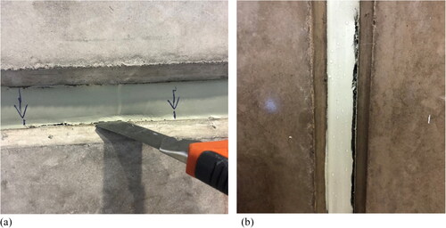
Fig. 8. a) Adhesion loosening in joint with building mastic. b) TDV-tube and crack in concrete panel at balcony etc.
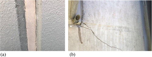
Fig. 9. Place Borås. Pressure difference on backside of façade against outside. Measurement interval of 1 sec. Approximate average windspeed 3 m/s and wind gusts of 7-8 m/s.
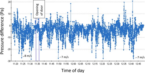
Fig. 10. Place Borås. See . Measurement period 11:23:13 till 11:27:15.
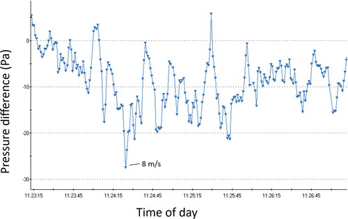
Fig. 11. a) Place Kungälv. Pressure difference on backside of façade against outside. Measurement interval of 1 sec. Approximate average windspeed of 4 m/s and wind gusts of 7-8 m/s. Data on wind speed is unavailable before 08:40. b) Place Gothenburg. Pressure difference on backside of façade against outside. Measurement interval 1 sec. Approximate average windspeed of 7 m/s and wind gusts of 10-11 m/s.
For object 1, at measurement point 5, a leakage of 0.06 l/h was measured at a pressure difference of 110 Pa over the pre-compressed sealing tape and at a pressure difference of 173 Pa, the leakage flow increased significantly to 0.3 l/h, as shown in . At measurement point 4, a leakage of 0.06 l/h, as shown in , was measured at a 52 Pa pressure difference over the pre-compressed sealing tape and at a 110 Pa pressure difference, there was an inward leakage of 0.27 l/h. At measurement point 7, the leakage was 0.02 l/h at a pressure difference of 52 Pa. When the pressure difference increased to 110 Pa, the measured leakage increased to 0.05 l/h as shown in .
Fig. 12. Object 2. The resulting leakage areas/measurement points in test round 1 and 2, marked and numbered. No leakage arose at the window with sheet-metal-clad reveals, at bottom left.
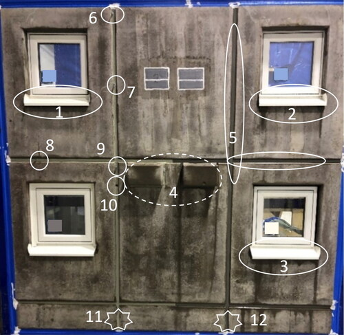
Fig. 13. Water leakage flow (liters/h) for the respective leakage point/area and pressure difference (Pa) over the respective leak in test round 2.
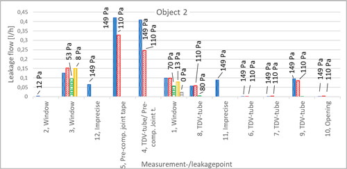
Fig. 14. Water leakage flow (liters/h) for the respective leakage point/area and pressure difference (Pa) over the respective leak in test round 2.
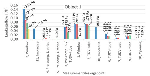
Fig. 15. Measured water leakage flow (liters/h) and pressure difference (Pa) during the four pulsating pressure steps (0, 150, 300, 450). Measurement points are marked in .
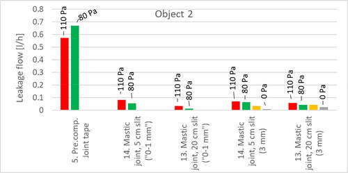
Fig. 16. Measured water leakage flow (liters/h) and pressure difference (Pa) during the four pulsating pressure steps (0, 150, 300, 450). Measurement points 13 and 14 were subjected to three pulsating pressure steps (0, 150, 300). Measurement points are marked in .
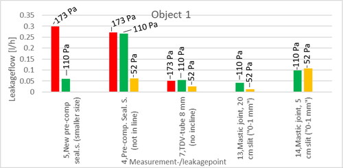
Fig. 17. Object 1. The resulting leakage areas/measurement points are also shown in test round 3, marked and numbered.
At measurement point 14, an inward leakage of 0.1 l/h arose at a pressure difference of 52 Pa for the shorter slit, as shown in . But for the longer slit, there was a lower leakage flow. One explanation may be that it is pure coincidence, i.e., how rivulets arise and run along the building mastic. In addition, an increased slit length does not necessarily lead to increased leakage flow as it can be assumed to be basically the same amount of water (the façade height above) that loads the slit. Since they were placed in the same vertical joint, but on either edge/side of the joint, it is not entirely possible to rule out that they may have affected each other. The shorter slit was placed approximately 1 dm above the longer slit to be able to separate the measurement with the respective collection chute.
Additional description of the leakage
The results show difficulties in getting the flashing under windows to attach to concrete in corners and angles as shown in . One reason could be that it was probably assembled without primer. Additionally, water could be transported in the surface layer of textile materials as shown in . The design and sealing of exterior flashing of metal against window frames seem to be remarkably difficult or impossible to make completely rain-proof. Flashing under windows had loosened in the angles which explains both leakage and leakage route as shown in .
Fig. 18. Flashing under a window had loosened in the angles which explains both leakage and leakage route.
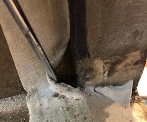
Fig. 19. Pre-compressed tape (black color) around window.
In addition, it seems difficult or perhaps impossible to achieve a rainproof solution with pre-compressed sealing tape and it was saturated with water (not investigated for pressure equalized walls or for no pressure difference over the sealing tape). Moreover, the measurements indicate that worse pre-compressed sealing tape and worse precision in assembly lead to greater leakage.
It could be noted that water could not be drained out via TDV tubes because the tube opened into the wall in such a way that the water could not hit the opening and thereby be directed out as shown in . However, the TUDV tubes had a solution that may be able to collect water, but that turned out to be counteracted by the airflow into the TUDV tube that pushed water into the wall as shown in .
As far as the author is aware, there is no documentation that proves that concrete sandwich walls in Sweden are pressure equalized (pressure equilibrium). According to a rule of thumb, the inside of the outer wall needs to be 20 times tighter than the outside of the outer wall, in order to achieve pressure equalization within the wall in relation to the outside (Rousseau et al., Citation1998). Since TDV tubes represent a relatively small area, this means that the inside must be completely airtight, which is probably difficult or perhaps impossible to ensure. In these tests, however, pressure differences have arisen over the façade layer (outer concrete panel) at all pressure steps with wind pressure loads and the inside has been quantified to be approximately 10 times more airtight than the openings in the outside.
Conclusions
Inspections reveal too narrow joint width in 80 of 106 measured joints, which can explain adhesion loosening/cracks in joints in eight of 11 buildings. Additionally, in eight of 11 buildings, concrete cracks were found in long wall elements. Also, other types of numerous non-conformities were found. Measurements in the field showed pressure differences which mean no pressure equalization (pressure equilibrium) is achieved, which is also confirmed by lab measurements. This can increase the risk of leakage through openings (such as TDV tubes) and leaks due to the driving force of air pressure differences.
Lab tests showed rain leakage occur at window-wall even without wind load/pressure differences and via TDV tubes at relatively low air pressure differences. However, joints with building mastic were rain-proof against driving rain. Moreover, a new type of joint seal of pre-compressed sealing tape had a lot of leakage and the sealing tape became water saturated. The study points out that TDV openings with overlapping joints may possibly have a better function than TDV tubes in terms of resisting driving rain and enabling drainage.
The leakage flow was measured at between 0.1-0.4 liters/h at most in the respective type of leakage point. Most leakage points can be found at half the façade height, so the leakage flow in these cases corresponds at least to a ratio of 0.1-0.4% of the vertical water flow cross a unit width of the façade at the given height. The highest leakage rate is almost in parity with the lower part of the interval, 0.5-2%, that was stated in a previous study for other kinds of façades (Olsson, Citation2017a). However, a certain proportion of the leakage could not be measured as it was absorbed by the concrete or accumulated in insulation and thus could not be included, which is why the leakage flows are likely to be underestimated in this study. Even though several different types of details/seals/openings in the same test wall were combined, the results can be considered representative of the current pressure differences across the respective details/seals/openings.
This study can directly point to some areas for improvement: inadequate dimensioning of vertical joint widths, incorrect installation of TDV tubes or absence of TDV openings, inadequate opening area in façades leading to the occurrence of pressure differences, risk of leakage via TDV tubes if pressure equalization in the wall is deficient, water could not be drained out via TDV tubes, inadequate installation of flashing and material selection under window frames, joints were not driving rain proof with the new sealing method of pre-compressed sealing tape.
A fundamental problem is that verified solutions often seem to be missing, which means that there may not even be the right prerequisite to achieve a secured function. In the literature, two-stage sealing is considered safer than single-stage sealing.
Future work should focus on the testing of improved and better solutions. Future work should also study cracked concrete and develop solutions to reduce leakage in cracked concrete and its consequences.
Disclosure statement
No potential conflict of interest was reported by the author(s).
Additional information
Funding
References
- Brycke, E., and C. Svensson Tengberg. 2019. Fukt i prefabricerade betongsandwichelement (Moisture in Precast Sandwich Elements (ID:13651). Stockholm: SBUF Svenska Byggbranschens Utvecklingsfond.
- Farmington, E. S., T. Anderson, L. Grant, and R. Seraderian. 2019. Precast concrete–to–precast concrete facade joints using precompressed expandable foam. PCI Journal 64 (6):11. doi:10.15554/pcij64.6-05
- FIB 2014. Planning and design handbook on precast building structures, Manual - textbook (Bulletin 74). International Federation for Structural Concrete.
- FIB 2017. Precast Insulated Sandwich Panels. State of the art report - State of the art report (Bulletin 84). International Federation for Structural Concrete.
- Hasselblad, V., and A. Andersson. 1972. Joints in facades made up of precast concrete sections. Stockholm: National Swedish Building Research Summaries (R42:1972).
- Jerling, A., and B. Schechinger. 1983. Fogars beständighet - Fogar i ytterväggar “Joint resistance - Joints in exterior walls”(R89). Statens råd för byggnadsforskning 790200-0. Stockholm: Chalmers University of Technology, Gothenburg.
- Jerling, A., B. Nylander, and P. G. Burström. 1988. Fogar i byggnaders ytterväggar. Stockholm: Byggforskningsrådet.
- Kudder, R. J., and J. L. Erdly. 1998. Water leakage through building facades. ASTM International.
- Lacasse, M. A., H. Miyauchi, and J. Hiemstra. 2009. Water penetration of cladding components—results from laboratory tests on simulated sealed vertical and horizontal joints of wall cladding. Journal of ASTM International 6 (6):1–21. doi:10.1520/JAI102048
- Olsson, L. 2017a. Rain intrusion rates at facade details - a summary of results from four laboratory studies. In 11th Nordic Symposium on Building Physics, NSB2017, 11-14 June 2017, 132, 387–92.
- Olsson, L. 2017b. Rain resistance of façades with façade details: A summary of three field and laboratory studies. Journal of Building Physics 41 (6):521–32.
- Rousseau, M. Z., G. F. Poirier, and W. C. Brown. 1998. Pressure Equalization in Rainscreen Wall Systems. National Research Council of Canada. Construction Technology update No.17, Ottawa, Canada. doi:10.4224/40002854
- Straube, J. 2013. High performing precast concrete building enclosures: Rain control. Ontario: Building Science Corporation. https://buildingscience.com/sites/default/files/migrate/pdf/2013-05-23_CPCI%20White%20Paper%20Final.pdf
- Svensk-Byggtjänst 2021a. AMA Hus 18-21, General material and workmanship specifications. Stockholm: Svensk Byggtjänst.
- Svensk-Byggtjänst 2021b. RA Hus 21 (Advice and instructions). Stockholm: Svensk Byggtjänst.
- Svensson Tengberg, C., L. Olsson, and C.-E. Hagentoft. 2021. Risk assessment of joint sealing tape in joints between precast concrete sandwich panels resilient to climate change. Buildings 11 (8):343. doi:10.3390/buildings11080343