
Abstract
We review recent advances on temporal localized structures in optical resonators. Because they can be individually addressed, localized structures may be used as elementary information bits which can be stored in an optical cavity. We disclose the conditions required for their existence and we present a selection of experimental results illustrating their properties in different optical systems. We also show how they can be temporally tweezed by modulating a parameter of the resonator, thus enabling bit reconfiguration and clocking.
Graphical Abstract
1. Introduction
Extended dissipative systems may exhibit stable localized solutions characterized by a correlation range much shorter than the size of the system hosting them. These ‘localized structures’ (LSs) can be individually addressed by a local perturbation, without affecting their surrounding environment. Spatial localized structures are ubiquitous in nature [Citation1–Citation5] and they have been widely investigated in a large variety of systems. Beyond their fundamental interest, LSs have been actively sought in optical resonators as elementary bits for information processing [Citation6–Citation9]. The idea is to use the transverse size of an optical resonator as a blackboard, where light bits can be individually written and erased, thus forming reconfigurable optical memory arrays [Citation10]. For hosting spatial LSs, a dissipative system is required to be ‘extended’, i.e. to have a large aspect-ratio or, for an optical resonator, to have a large Fresnel number. In fact, this condition can be easily understood when considering that a system governed by its boundary conditions cannot exhibit independent structures. Short correlation ranges imply instead that the system is governed by its bulk nonlinearity [Citation11]. Furthermore, LSs appear in presence of subcritical instabilities, leading to coexistence between different solutions [Citation12]. In the most common form, LSs involve a subcritical Turing instability forming a periodic pattern state coexisting with a homogeneous solution. In these conditions, an infinite set of coexisting solutions may appear, each one formed by stable fronts linking arbitrary portions of the pattern solution with the homogeneous one [Citation13–Citation15]. The regime of LSs is achieved when the pattern becomes fully decomposable in each period, since a single localized structure can be considered an independent cellular unit of the pattern [Citation16].
Spatial LSs have been observed in the transverse section of broad-area semi-conductor vertical-cavity surface-emitting lasers (VCSELs) injected by a coherent electromagnetic (EM) field [Citation17] and they have been named ‘cavity solitons’ (CS) [Citation10]. Few years later, spatial LSs have been observed in laser systems, where they arise from spontaneous emission noise without requiring the presence of an injected field [Citation18,Citation19]. Because these lasing LSs, also called ‘laser solitons’, appear in a phase invariant system, their dynamical ingredient, properties and formation mechanism are different from the ones of CS appearing in driven resonator [Citation6,Citation20].
Recent works have addressed the question of whether the concept of LS can be extended to the time domain or, equivalently, to the propagation direction of the EM field. In this context, the system size is given by the longitudinal dimension of the resonator and the notion of large-aspect ratio can be formulated by requiring that the cavity round trip must be much larger than the active material timescales. On the other hand, modulational instabilities are well known to occur along the propagation directions of fiber resonators, destabilizing the stationary solution and leading to the formation of a periodic train of pulses [Citation21]. Temporal LSs may form when the modulational instability occurs sub-critically. In analogy with the spatial case, temporal LSs correspond to cellular units of the temporal pattern; hence, they are individually addressable pulses traveling inside the cavity.
Because LSs are purely dissipative structures determined by the nonlinear behavior of a physical system, they have been often related to dissipative solitons (DSs) [Citation22,Citation23]. Yet, this link should be used with care as it is often a source of misunderstandings. While LSs are operatively defined by their individual addressability, DSs are not necessarily required to feature this property. For example, DSs usually observed in mode-locked fiber or Ti:sapphire lasers [Citation23] cannot be considered as LSs because the gain recovery time is so large in these media (ms in doped fibers) that the limit of large aspect-ratio required for hosting individually addressable structures,
, is very difficult to be experimentally realized. This was pointed out as early as the 1990s, when fiber lasers were proposed as storage rings for information bits [Citation24]. Here, the gain level needed to be adjusted as a function of the number of pulses in the cavity, thus preventing from storing an arbitrary sequence of bits at a fixed gain level [Citation25].
In this review, we present recent advances in implementing temporal localized structures in optical resonators. We will show how they can be used to store information in optical cavities and how can they be manipulated. Several systems will be described: (i) Kerr fiber resonators injected by an external EM field, hosting the temporal equivalents of CSs, (ii) passively mode-locked semiconductor lasers operated in the limit of cavity round-trip times much larger than the semiconductor gain recovery time, (iii) excitable semiconductor laser with delay hosting phase LSs, and (iv) VCSELs with polarization sensitive delays hosting vectorial LSs. While the material response of Kerr fiber resonators can be considered instantaneous, the finite response time of the semiconductor material affects the other three systems described. In addition, the former is described by a partial differential equation with a distributed and quasi-instantaneous nonlinearity, the so-called Lugiato–Lefever equation (LLE) [Citation26], while the latter are described by delay differential equations (DDEs). These differences have a deep impact on the equations of motion of the LSs because they introduce causality in the system, thus breaking parity symmetry along the propagation direction. The manipulation of LS with and without this symmetry is described in Section 3.
2. Storing information in optical cavities
2.1. Temporal cavity solitons in Kerr fiber resonators
Temporal CSs were the first optical LSs to be observed and studied in the time-domain. They can be described as ultrashort pulses of light that persist in coherently driven, passive, nonlinear optical ring resonators [Citation27], where diffraction is eliminated through transverse confinement of light in a waveguide [see Figure ]. They maintain constant temporal shape and energy: the nonlinearity of the waveguide balances dispersion-induced temporal spreading, and all the energy they lose is replenished by the coherent field driving the cavity. As their self-localization and energy-balance are both enabled by a quasi-instantaneous optical nonlinearity, temporal CSs exhibit all the characteristic features associated with LSs, i.e. coexistence [Citation27], individual addressability [Citation28], and mobility [Citation29]. Although they are similar in many ways to their spatial counterparts [Citation17], temporal CSs possess one significant advantage: they are inherently immune to material inhomogeneities that hinder the performance of spatial CSs [Citation30]. Taken together, these features suggest temporal CSs to constitute an ideal support for bits in an optical buffer [Citation31].
Figure 1. (a) Schematic illustration of temporal cavity solitons circulating in a Kerr nonlinear optical ring resonator driven with a continuous wave (cw) laser. (b) Temporal intensity profile of a 2.6 ps cavity soliton persisting in a fiber ring resonator, measured with a sub-picosecond resolution optical sampling oscilloscope. The blue solid line shows corresponding results from LLE simulations. (a) and (b) were adapted from [Citation31] and [Citation47], respectively.
![Figure 1. (a) Schematic illustration of temporal cavity solitons circulating in a Kerr nonlinear optical ring resonator driven with a continuous wave (cw) laser. (b) Temporal intensity profile of a 2.6 ps cavity soliton persisting in a fiber ring resonator, measured with a sub-picosecond resolution optical sampling oscilloscope. The blue solid line shows corresponding results from LLE simulations. (a) and (b) were adapted from [Citation31] and [Citation47], respectively.](/cms/asset/398db2c2-71d2-45e2-9c7c-454841c09b66/tapx_a_1321501_f0001_oc.gif)
Temporal CSs were first observed and studied in macroscopic ring resonators constructed of single-mode optical fibers [Citation27]. More recently, they have also attracted significant attention in the context of monolithic microresonators, where they play a key role in the generation of coherent optical frequency combs [Citation32–Citation38]. Both of these systems exhibit a quasi-instantaneous focusing Kerr nonlinearity, and their dynamics is governed (to first order) by a driven-damped nonlinear Schrödinger equation [Citation32,Citation39,Citation40]. This equation is formally identical with the celebrated mean-field Lugiato–Lefever equation of spatially diffractive Kerr cavities [Citation26]. The LLE is well-known to host a subcritical modulation (or Turing) instability that gives rise to a patterned state coexisting with a stable homogeneous state. As alluded to in the introduction above, (temporal) CSs arise precisely under conditions of such co-existence, corresponding to mixed-states that coincide with the patterned state in a certain localized region, and with the homogeneous state elsewhere [Citation10,Citation41].
The prospect of storing information as temporal CSs in single-mode fiber ring resonators was first alluded to in 1993 by Wabnitz, who used the time-domain LLE to gain insights on spatial solitons in diffractive cavities [Citation42]. The possibility did not, however, initially attract significant attention, arguably because of the strong research focus on diffractive systems at the time. It was not until 2010 that interest in temporal CSs intensified, following the pioneering first experimental observations by Leo et al. [Citation27].
The experiments of Leo et al. were based on a 380 m long passive ring cavity made of standard telecommunications optical fiber, driven with a narrow linewidth continuous wave laser at 1550 nm [Citation27]. To excite temporal CSs, the authors launched an isolated ‘addressing’ pulse – derived from an external mode-locked laser – into the cavity, and observed it reshape into a 4 ps pulse persisting inside the resonator. The pulse circulated unchanged for hundreds of thousands of cavity transits, thus demonstrating the double balance of dispersion and losses with, respectively, nonlinearity and driving. The authors further demonstrated the coexistence of several pulses, and the system’s ability to act as an all-optical memory, by storing a 15-bit data stream. Corroborated by the excellent agreement with simulations of the time-domain LLE, the observations represented very clear evidence of temporal CSs.
Due to issues with cavity stabilization, the experimental configuration of Leo et al. only allowed temporal CSs to be sustained for a few seconds. Whilst sufficient for positive proof-of-concept, the limitation prevented detailed study of CS dynamics. In 2013, Jang et al. reported on an improved fiber cavity set-up, where temporal CSs could be sustained for periods in excess of 30 min [Citation43]. Quite surprisingly, the authors discovered an ultra-weak interaction mechanism that caused coexisting solitons to slowly attract or repel each other. The interactions were explained to arise due to electrostriction [Citation44–Citation46]: a leading CS acts as an impulse for the generation of transverse acoustic waves that cause minute changes in the refractive index of the optical fiber, thus influencing the velocity of a trailing CS [Citation43]. Given that the strength of the refractive index perturbations was estimated as few parts-per-trillion (), the ability to even observe the interactions in a noisy laboratory experiment represents a dramatic demonstration of the robustness of temporal CSs.
From the perspective of information storage applications, interactions between solitons are unwanted because they distort the optically stored data stream. In 2015, Jang et al. demonstrated that they can be readily overcome by applying a suitable phase modulation on the cavity driving field [Citation29], as described in more details in Section 3.1. By leveraging this approach, Jang et al. have recently demonstrated a robust all-optical buffer based on temporal cavity solitons that is capable of storing 4536 bits of data at 10 Gb/s [Citation47]. This constitutes state-of-the-art in memory devices based on optical LSs.
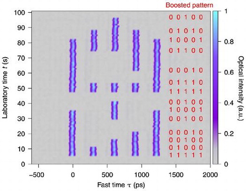
Direct phase modulation of the cavity driving field has also enabled unprecedented flexibility over the addressing of temporal CSs [Citation28]. Figure shows a selection of pertinent experimental results. Here, Figure (a) and (b) show how a single CS can be excited and erased, respectively, by abruptly boosting the amplitude of a Gaussian phase modulation pulse applied on the cavity driving field [Figure (c)]. Experimental results illustrating more complex manipulations are shown in Figure (d), where five solitons (spaced by 300 ps) are controllably turned on and off by abrupt boosts of the corresponding phase modulation amplitudes. Note that the false-color plot corresponds to a vertical concatenation (with slow/laboratory time t running bottom to top) of successive oscilloscope traces recorded at the cavity output. In addition to showcasing extraordinary addressing flexibility, a particularly significant aspect of the results shown in Figure is that they represent the first experimental demonstration of selective erasure of temporal CSs, which can be considered as a defining feature of LSs. More recently, it has also been demonstrated that analogous results can be obtained by modulating the driving field amplitude instead of phase [Citation48].
Figure 2. (a), (b) Oscilloscope traces showing the real-time transient dynamics of CS (a) writing and (b) erasing. Both operations are achieved by boosting the amplitude of a 70 ps Gaussian phase-modulation pulse applied on the cavity driving field for ten roundtrips. The oscilloscope trace in (c) shows the synchronously applied phase modulation signal. Red curves in (a) and (b) correspond to numerical simulations. (d) Experimental false-color plot showing successive oscilloscope traces of the optical intensity at the cavity output. The traces were recorded at 1 frame/s with a 40 GSa/s real-time oscilloscope. The solid red dots indicate fast and slow time coordinates where the phase modulation amplitudes are boosted for 10 roundtrips. All data from [Citation28].
![Figure 2. (a), (b) Oscilloscope traces showing the real-time transient dynamics of CS (a) writing and (b) erasing. Both operations are achieved by boosting the amplitude of a 70 ps Gaussian phase-modulation pulse applied on the cavity driving field for ten roundtrips. The oscilloscope trace in (c) shows the synchronously applied phase modulation signal. Red curves in (a) and (b) correspond to numerical simulations. (d) Experimental false-color plot showing successive oscilloscope traces of the optical intensity at the cavity output. The traces were recorded at 1 frame/s with a 40 GSa/s real-time oscilloscope. The solid red dots indicate fast and slow time coordinates where the phase modulation amplitudes are boosted for 10 roundtrips. All data from [Citation28].](/cms/asset/604d1f41-b80c-44cb-8efc-1cf151a0a018/tapx_a_1321501_f0002_oc.gif)
2.2. Localized mode-locked pulses
Semiconductor media response time is typically in the nanosecond range, owing to their carrier recombination time . This fast time scale makes semiconductor media promising for achieving the large aspect-ratio condition required for temporal localization. Accordingly, temporal LSs have been recently observed in semiconductor lasers mounted in compound cavities configurations. The first configuration we describe consists of an electrically biased broad-area (
m) VCSEL mounted in an external cavity closed by a resonant saturable absorber mirror (RSAM), as shown in Figure . Passive Mode-Locking is achieved when placing the RSAM surface in the Fourier transform plane of the VCSEL near-field profile [Citation49]. While this scheme leads to conventional mode-locking pulses for cavity round trips shorter than the gain recovery time (
), we operate the system in the regime of long cavities, i.e.
, and for bias currents below the lasing threshold of the compound system (
mA) [Citation50]. In these conditions, a large variety of pulsating emission states coexist, each one characterized by a different number N of pulses circulating in the cavity or, when having the same value of N, characterized by different pulse arrangements. The number of pulses N spans from zero up to a maximum
which depends on the cavity length. This generalized multistability provides the dynamical ingredients for the formation of LSs. The state at which
corresponds to the fully developed temporal pattern which is, together with the coexisting stable off solution, at the origin of the LS formation scenario. In Figure (a)–(d), we show a variety of these coexisting solutions. In analogy to spatial LSs, the temporal pattern in Figure (d) is fully decomposable because any pulse of this solution can be set on or off by a perturbation pulse.
Figure 3. Experimental Setup: Temperature-stabilized VCSEL and RSAM. Coll.: Aspheric Lens, BS : Beam Splitter, M: Mirror and D1: Detector and CCD cameras. Panels (a)–(f) Examples of coexisting temporal traces for mA and cavity length of 2.25 m, corresponding approximately to a round-trip time
ns. The panels (a)–(c) correspond to
pulses per round trip, respectively. The maximal number of pulses is
as depicted in panel (d). All data from [Citation50]. Panels (e) and (f) Spatio-temporal diagrams showing writing (g) and erasing (h) of a LS by an electrical pulse in the pumping current. The current values are represented in color scales, while the optical pulses trajectories are represented by black lines.
mA. The amplitude and the width of the writing/erasing pulse are
mA and
ns, respectively.
![Figure 3. Experimental Setup: Temperature-stabilized VCSEL and RSAM. Coll.: Aspheric Lens, BS : Beam Splitter, M: Mirror and D1: Detector and CCD cameras. Panels (a)–(f) Examples of coexisting temporal traces for mA and cavity length of 2.25 m, corresponding approximately to a round-trip time ns. The panels (a)–(c) correspond to pulses per round trip, respectively. The maximal number of pulses is as depicted in panel (d). All data from [Citation50]. Panels (e) and (f) Spatio-temporal diagrams showing writing (g) and erasing (h) of a LS by an electrical pulse in the pumping current. The current values are represented in color scales, while the optical pulses trajectories are represented by black lines. mA. The amplitude and the width of the writing/erasing pulse are mA and ns, respectively.](/cms/asset/4de7f893-eff6-4868-bcb9-0d27967cb23c/tapx_a_1321501_f0003_oc.gif)
Writing and erasure of temporal LSs is usually implemented by perturbing the system with an optical pulse injected inside the cavity, as described in Section 2.1. While addressing would be in principle feasible using optical injection, here we take advantage of the fast response of semiconductor media to pumping current modulation and we address LSs by adding electrical pulses to the laser bias [Citation51,Citation52]. This parameter, which is commonly used in optoelectronics for converting an electrical bit stream into an optical one at rates higher than 10 GHz [Citation53], appears to be very convenient for LSs’ applications to information processing.
In order to monitor the addressing process, we depict the laser intensity output using the so-called space-time diagrams, where the time trace is transformed into a two-dimensional representation with a folding parameter equal to the pulse round trip T. Accordingly, the round-trip number n becomes a pseudo-time variable while the pseudo-space variable corresponds to the timing of the pulse inside a particular round trip. This representation is similar to the one used in Figure (d) and it has also been proposed for delayed systems [Citation54]. On these space-time diagrams, the bias current evolution is represented using a color code, while the trajectory of the LS is represented by a black trace in Figure (e)–(f). The system is prepared in the multistable parameter region where LSs exist, then a current pulse is added to the bias. Its amplitude is sufficiently large to bring the system above threshold, i.e. into the parameter region where only the fully developed temporal pattern solution is stable. If the electrical pulse is sufficiently short, a single LS will be excited and it will remain once the perturbation is removed. The electrical pulse used has a rectangular shape with a duration of ns and it is applied synchronously with the pulse round trip-time for
consecutive round trips. In Figure (e), we illustrate a writing operation starting from a condition where no LS exist in the cavity before applying the writing pulse. Similarly, a single localized structure can be erased using a negative bias current pulse bringing locally the system in the region where only the off solution is stable (Figure (f)). Addressing operations can be successfully implemented starting from other initial conditions [Citation52], provided that the separation between the writing pulse and preexisting LSs allows for sufficient gain recovery. This latency indicates that, even if the intensity profile of a LS exhibits a temporal width of approximately 10 ps, its effective width is ultimately fixed by the characteristic time of the underlying gain recovery process, which is typically about 1 ns.
2.3. Phase localized pulses
As for laser solitons vs. CSs in the spatial domain, there is an important difference between localized mode-locked pulses described in Section 2.2 and temporal CSs described in Section 2.1. While the former appear in a phase invariant system, the latter appear in a resonator where the injection of an external EM field breaks the phase rotation invariance, leading to phase-locked pulses. In such systems without phase symmetry, several other forms of localized states can be envisioned if the nonlinear medium is oscillatory. It is worth noting that this difference goes beyond the distinction between passive (i.e. Kerr or absorptive) vs. active (amplifying) devices, since the oscillatory nature of the medium fundamentally changes the dynamics. When the forcing is parametric for instance, two stable solutions locked at different phases of the forcing can coexist. Fronts connecting these solutions consist in a rotation of the order parameter and carry, therefore, a chiral charge. In one dimension repulsive interaction between these domain walls (of Bloch type) may lead to the stable existence of localized states consisting of one phase embedded in a sea of the other phase [Citation15]. In the optical context, such localized states have been extensively analyzed in the transverse domain [Citation55–Citation57] and the order parameter is the optical phase. When the forcing is nearly resonant and only one stable phase locked state exists, homoclinic fronts consisting fundamentally of optical phase rotations which connect this state to itself have been predicted both in the transverse domain [Citation58] and along the propagation direction [Citation59]. Nevertheless, the experimental demonstration of existence of these dissipative soliton-like states has been achieved only very recently along the propagation direction with the experimental scheme shown in Figure [Citation60].
Figure 4. (a) schematics of multimode laser with coherent forcing. The active medium is an electrically pumped semiconductor amplifier, which is enclosed in a ring cavity whose length is accuratedly controlled by a piezo actuator. Conceptually different from forcing a nonlinear resonator as done in microrings or Kerr fibers, this experiment consists in forcing a nonlinear oscillator. The resulting localized states consist in phase rotations. (b) space-time diagram showing solitary waves colliding with each other or with chaotic domains. The asymmetry of the domains results from the lack of parity symmetry in systems with noninstantaneous nonlinearity. Single-shot real-time measurements show the different velocities of each domain. (c) cut along the red line in (b). (d) time-resolved measurement of the optical phase by heterodyning shows that each structure consists of phase rotation (insets) and that these rotations were already present in the chaotic domains from which they have emerged. From [Citation60].
![Figure 4. (a) schematics of multimode laser with coherent forcing. The active medium is an electrically pumped semiconductor amplifier, which is enclosed in a ring cavity whose length is accuratedly controlled by a piezo actuator. Conceptually different from forcing a nonlinear resonator as done in microrings or Kerr fibers, this experiment consists in forcing a nonlinear oscillator. The resulting localized states consist in phase rotations. (b) space-time diagram showing solitary waves colliding with each other or with chaotic domains. The asymmetry of the domains results from the lack of parity symmetry in systems with noninstantaneous nonlinearity. Single-shot real-time measurements show the different velocities of each domain. (c) cut along the red line in (b). (d) time-resolved measurement of the optical phase by heterodyning shows that each structure consists of phase rotation (insets) and that these rotations were already present in the chaotic domains from which they have emerged. From [Citation60].](/cms/asset/8df918a1-2485-4f58-8391-a04d080a6777/tapx_a_1321501_f0004_oc.gif)
The oscillatory medium is a semiconductor laser which consists of an Antireflection-coated gain medium enclosed in a single transverse mode but approximately 1 m long (and therefore heavily multi-longtudinal mode) ring cavity closed by high reflectivity mirrors. The nearly resonant forcing is provided by a semiconductor laser whose frequency is tuned within a few GHz from the ring laser lasing mode. For sufficiently small detuning or sufficiently large forcing, the phase of the ring laser is stably locked to that of the external forcing. Close to the unlocking transition, non-dispersive solitary waves can emerge from initially chaotic domains as shown on (b), which also shows the different velocity of solitary waves fronts. The chiral charge carried in the solitary waves is already enclosed in the chaotic domains, as was observed by heterodyning the field emitted by the ring laser with the forcing beam field, giving access to real-time amplitude and phase information. This measurement is shown on Figure (d), where the insets show the real-time measurement of the electric field phase, which is particularly instructive when compared with the numerically calculated one in the case of phase locked cavity solitons (see e.g. [Citation8]). Here, only one direction of phase rotation is observed, which is attributed to the lack of parity symmetry in propagative oscillatory media with non-instantaneous nonlinearity [Citation61]. In contrast with temporal cavity solitons whose existence is related to a neighboring modulational instability, the emergence of these solitons is related to a commensurate-incommensurate nonequilibrium transition [Citation62] and to the vicinity of a saddle-node on circle bifurcation [Citation60]. The longest real-time measurements technically achievable with available equipment at that time have demonstrated perfectly conserved shape of the localized states over 40 km propagation [Citation61].
Figure 5. (a) temporal profile of dissipative soliton based on the phase space topology of an excitable system with delayed feedback. This shape is strongly reminiscent of that of excitable spikes measured with identical detection system [Citation64]. (b) localized states are nucleated when a phase jump is applied on the forcing beam via an electro-optic phase modulator. Each arrow indicates the fast and slow time coordinates at which a 100 ps duration phase jump is applied (within one single roundtrip). When such a phase perturbation reaches the nonlinear element sufficiently close to a pre-existing structure it can displace it (at coordinates (5,45)) or even cancel it completely (at coordinates (6.5,42)). From [Citation63].
![Figure 5. (a) temporal profile of dissipative soliton based on the phase space topology of an excitable system with delayed feedback. This shape is strongly reminiscent of that of excitable spikes measured with identical detection system [Citation64]. (b) localized states are nucleated when a phase jump is applied on the forcing beam via an electro-optic phase modulator. Each arrow indicates the fast and slow time coordinates at which a 100 ps duration phase jump is applied (within one single roundtrip). When such a phase perturbation reaches the nonlinear element sufficiently close to a pre-existing structure it can displace it (at coordinates (5,45)) or even cancel it completely (at coordinates (6.5,42)). From [Citation63].](/cms/asset/ced9e1fc-0e4a-4528-818d-8be3fa041790/tapx_a_1321501_f0005_oc.gif)
Remarkably similar observations have been realized by enclosing a nonlinear node close to a saddle-node bifurcation into a delayed feedback loop [Citation63]. In this case, the experiment consisted of a single longitudinal and transverse mode laser under coherent forcing. Close to the unlocking transition, this system displays a neuron-like response to external perturbations: small perturbations are followed by a linear relaxation process towards the stable fixed point while perturbations which overcome a certain threshold push the system to undergo a complete phase rotation of the laser with respect to the forcing, the latter orbit being independent of the details of the perturbation[Citation64–Citation66]. Considering the existence of this well-defined threshold in terms of phase shifts occurring in the driving beam, such a system may have strong relevance for the optical processing of coherent, phase encoded information (see e.g. [Citation67,Citation68]). This feature was particularly highlighted in [Citation63] where a demonstration of the ignition and erasure of phase encoded spikes was achieved by applying perturbations in the driving beam via an electro-optic phase modulator (see Figure ). In the particular case of this experiment, the amplitude variation associated to the phase rotation is remarkably small (a few %) and therefore the dynamics can be completely described by that of the phase of the laser field, highlighting the connection between these localized states and sine-Gordon topological solitons.
The generation of localized states based on enclosing a nonlinear node with well defined phase space structure was also observed in several other contexts. The case of a bistable system (two stable fixed points coexisting with an unstable one) with delayed feedback was initially analyzed in [Citation69] in the case of a laser with opto-electronic feedback and showed coarsening dynamics: the most stable state invades the whole system via motion of switching fronts repelling or attracting each other. The pinning of fronts which is typical of localized states, as illustrated in Section 1, was later achieved by modulating a parameter in the feedback loop, which led to the demonstration of localized states in time domain [Citation70]. Stabilization of fronts was also achieved by using anti-periodic boundary conditions which corresponded to front dynamics over a Moebius strip geometry [Citation71]. Finally, the nucleation of temporal localized states based on enclosing a neuron-like element in a feedback loop was also realized recently building on the vicinity of a weakly saturated Andronov–Hopf bifurcation. In this last case, the excitable element is a resonant tunneling diode and the excitable dynamics is of the FitzHugh–Nagumo type [Citation72].
2.4. Vectorial localized pulses
Vectorial Localized Structures are originated by a rotation of the polarization vector state over the Poincaré sphere, thus corresponding to anti-phase localized pulses in the two orthogonal polarization components. These purely vectorial LSs leave the total intensity essentially constant and, therefore, they do not involve any relevant carrier dynamics. Accordingly, these LSs rely on time scales faster than the gain recovery time, which lead to shorter localized pulses and increased addressing rate. Vectorial LSs have been implemented in a single transverse-mode VCSEL placed in a polarization-sensitive double external cavity [Citation73]. Because of their symmetric structure, VCSELs lack anisotropies strong enough to pin the polarization direction and competition between orthogonal linearly polarized states is easily induced by (anisotropic) optical perturbations. The polarization-sensitive double external cavity induces such a competition by selecting one of the linearly polarized states (say Y) and feeds it back twice into the laser: along the first path, Y is re-injected after a time delay and termed polarization selective feedback (PSF) while along the second path Y is rotated to the orthogonal polarization orientation and re-injected with time delay
, which corresponds to crossed-polarization re-injection (XPR) (Figure (a)). The XPR induces cross-gain modulation between the two linear polarization components [Citation74], thus enhancing their competition and leading to anti-phase polarization dynamics [Citation75,Citation76]. For properly chosen parameters, the polarization resolved outputs of the VCSEL exhibit a train of pulses separated by
ns, as shown in Figure (b). These polarization pulses appear anti-correlated and the corresponding total intensity time trace is almost constant, thus revealing the vectorial character of this dynamics. The situation shown in Figure (b), displaying one pulse per round trip, coexists with many different situations having different numbers and arrangements of pulses per round trip. The system may evolve from one state to another in response to perturbations or parameter sweeps, in the latter case displaying a high degree of hysteresis. As an example of this generalized multistability, in Figure (c) and (d) we plot space-time diagrams showing the evolution of the X-polarized localized pulses for two different initial conditions. In Figure (c) we show the trajectories of two LSs which wander inside the cavity following a Brownian motion. The two trajectories are uncorrelated, thus indicating that the two localized pulses are independent. In Figure (d), we show instead three pulses which evolves like a rigid body, following the same Brownian trajectory. The three pulses form a molecular localized structure. Important enough, the bonding distance corresponds to the difference between the two time delays in our system,
, a parameter that can be experimentally tuned easily. A theoretical analysis, based on the Spin-Flip Model [Citation77] suitably modified for incorporating the effects of gain saturation, PSF and XPR, reproduces well the experimental finding [Citation73,Citation76]. A multiple time scale analysis allows to reduce the dynamics to a DDE for the evolution of a single variable, the orientation of the polarization along the equator of the Poincaré sphere. In particular it reveals that each pulse is associated to a polarization slip on the Poincaré sphere, as shown in Figure (e), thereby demonstrating their topological nature.
Figure 6. Panel (a) Experimental setup: L Lens, BS1 and BS2 Beam Splitters, PBS polarizing beam splitter, FR Faraday rotator, P polarizer, M Mirror. BS1 splits the output in two arms. Along one arm a PBS filter out X polarization Y is fed back by BS2 into the VCSEL. Along the second arm a FR with a polarizer select Y polarization and turn it into X component before reinjection into the VCSEL. Panel (b): Time signal of the Y (blue) and X (red) outputs when the VCSEL is submitted to XPR (rate %) and PSF (rate
%).
mA,
ns,
ns. Panels (c) and (d): Space-time diagrams of different situations with multiple LSs coexisting within the external cavity. (c): Two independent LSs and (d): a 3-pulse LS molecule separated by a time
. In (c) and (d)
ns and
ns. Panel (e) Numerically calculated temporal trace using the normalized Stokes representation of the dynamics. The trace corresponds to the situation where a single LS is present into the cavity. The trace length consists in
consecutive round trips. One notices that the polarization angle performs a full cycle while remaining close to the equatorial plane. All data from [Citation73].
![Figure 6. Panel (a) Experimental setup: L Lens, BS1 and BS2 Beam Splitters, PBS polarizing beam splitter, FR Faraday rotator, P polarizer, M Mirror. BS1 splits the output in two arms. Along one arm a PBS filter out X polarization Y is fed back by BS2 into the VCSEL. Along the second arm a FR with a polarizer select Y polarization and turn it into X component before reinjection into the VCSEL. Panel (b): Time signal of the Y (blue) and X (red) outputs when the VCSEL is submitted to XPR (rate %) and PSF (rate %). mA, ns, ns. Panels (c) and (d): Space-time diagrams of different situations with multiple LSs coexisting within the external cavity. (c): Two independent LSs and (d): a 3-pulse LS molecule separated by a time . In (c) and (d) ns and ns. Panel (e) Numerically calculated temporal trace using the normalized Stokes representation of the dynamics. The trace corresponds to the situation where a single LS is present into the cavity. The trace length consists in consecutive round trips. One notices that the polarization angle performs a full cycle while remaining close to the equatorial plane. All data from [Citation73].](/cms/asset/037cda59-66f7-43c4-81d9-af0130250208/tapx_a_1321501_f0006_oc.gif)
3. Manipulation of light bits
The section above has given a brief overview on the types of temporal LSs that can manifest themselves in different optical systems. With an eye to potential applications as bits in optical storage units, the discussion has focused in particular on experimental results demonstrating the ability to simultaneously support several independent LSs, and to individually address them. As described in the Introduction, both these features can be considered key defining features of LSs. In this section, we discuss yet another key feature of LSs: the fact that they can be easily moved around and manipulated. This feature is commonly referred to as ‘mobility’ or ‘plasticity’, and has been extensively studied in the context of spatial optical LSs [Citation8,Citation78–Citation82].
3.1. Quasi-instantaneous media
The mobility of (temporal) CSs discussed in Section 2.1 affords a simple qualitative explanation. Specifically, because the CSs sit atop a perfectly homogeneous background, they are not subject to any preferred positions or restoring forces. Accordingly, any gradient on the background field will cause an overlapping CS to move towards – and be trapped at – a point where the gradient vanishes. Mathematically, this phenomenon stems from the fact that the CS solutions of the LLE possess a neutral (or ‘Goldstone’) mode with zero eigenvalue [Citation82].
Of course, in the context of temporal CSs that arise in the propagation direction of the EM field, ‘motion’ manifests itself as a change in relative temporal delay rather than any physical position (recall that the CSs are in perpetual motion around the ring resonator). On the other hand, a change in delay must be accompanied by a relative difference in velocity. A temporal CSs drifting towards positive (negative) delays should be understood to do so because it possesses a group velocity that is larger (smaller) than that associated with the pump wavelength. It should now be straightforward to understand the physical phenomenon behind the mobility of temporal CSs: (phase) gradients on the background field induce a shift in the soliton’s instantaneous frequency, which when coupled to group-velocity dispersion, leads to a change in velocity [Citation29].
Gradients on the background field can arise inadvertently, leading to unwanted CS motion. The acoustic interactions mentioned in Section 2.1 can be ascribed precisely to such a scenario: gradients arise due to acoustic waves excited by a leading CSs, changing the velocity of a trailing soliton [Citation43]. More interesting is the possibility to artificially induce ‘control’ gradients so as to systematically control and manipulate CSs and their relative positions. Arguably, the most straightforward approach involves the phase modulation of the cavity driving field [Citation29]. Specifically, if a time-varying phase profile is applied on the driving field (and if the modulation is synchronized with the cavity roundtrip time), the quasi-homogeneous intracavity field will develop an identical phase profile. CSs circulating in the resonator will then be attracted to the peaks of the co-circulating intracavity phase modulation and remain trapped there. Of course, the trapped CSs can then be dynamically moved around, i.e. their relative temporal delays adjusted, by manipulating the phase profile applied to the driving field. In analogy with optical tweezers used to trap and manipulate dielectric particles, this procedure has been termed ‘temporal tweezing of light’ [Citation29].
The phase modulation scheme described above was demonstrated by Jang et al. in 2015 using a single-mode optical fiber ring resonator [Citation29]. Figure shows a selection of the experimental results obtained. First, Figure (a) shows the dynamical behavior of three temporal CSs propagating in the cavity in the absence of phase modulation. As can be seen, the CSs are initially excited with 800 ps relative separations, but slowly move closer as a result of an attractive acoustic interaction. In stark contrast, when the measurement is repeated in the presence of a sinusoidal phase modulation with frequency close to 10 GHz, the CSs can be seen to be precisely trapped to the modulation maxima [see Figure (b)]. Figure (c) shows an example of experimentally realized dynamical manipulation of temporal CS positions. Here, three CSs are trapped at the peaks of three separate Gaussian phase modulation pulses. The first and the third phase peaks (with delays of 0 and 2000 ps) are held at constant separation, whilst the delay of the middle one (initially at 1400 ps) is continuously translated back and forth over a 360 ps range. This results in the middle temporal CS exhibiting a corresponding motion relative to the first and the third soliton.
Figure 7. (a), (b) Dynamical evolution behavior of three temporal CSs circulating in a passive single-mode optical fiber ring resonator in the (a) absence and (b) presence of driving field phase modulation. Top curve in (b) shows the 10 GHz phase modulation profile. (c) Experimental result showing the real-time manipulation of temporal separations between picosecond CSs. As in Figure (c), the false-color plots have been constructed from successive oscilloscope traces recorded at the cavity output with a 40 GSa/s real-time oscilloscope and at a frame rate of 1 Hz (a), (b) and (c) 5 Hz. All data from [Citation29].
![Figure 7. (a), (b) Dynamical evolution behavior of three temporal CSs circulating in a passive single-mode optical fiber ring resonator in the (a) absence and (b) presence of driving field phase modulation. Top curve in (b) shows the 10 GHz phase modulation profile. (c) Experimental result showing the real-time manipulation of temporal separations between picosecond CSs. As in Figure 2(c), the false-color plots have been constructed from successive oscilloscope traces recorded at the cavity output with a 40 GSa/s real-time oscilloscope and at a frame rate of 1 Hz (a), (b) and (c) 5 Hz. All data from [Citation29].](/cms/asset/63cb2b1c-3e2f-4cbb-9926-a72cd97cff2b/tapx_a_1321501_f0007_oc.gif)
The results in Figure show how phase modulation of the cavity driving field enables (i) suppression of soliton interactions and (ii) dynamical control of temporal separations between picosecond pulses of light. Clearly, the ability to robustly trap CS to precise positions is valuable for the storage of information, with the ability to change the soliton positions providing for the added functionality of reconfigurability. In addition, the facility to arbitrarily position existing CSs can be leveraged for the controlled study of their (short-range) interactions, and this concept has very recently been used to experimentally study the dynamics of colliding temporal CSs [Citation83]. It was found that, depending on the system parameters, two colliding CSs can either merge into one or annihilate each other, thus demonstrating the dissipative nature of the interaction. These findings are particularly important for elucidating the dynamics that take place when a sequence of CSs is excited via continuous variation of system parameters [Citation33,Citation84], as is conventional in the context of microresonator frequency combs [Citation33–Citation37].
3.2. System with broken parity symmetry
At variance with Kerr fiber resonators, cavities based upon semiconductor media feature a finite response time due to the carriers recombination rate. Hence, these systems cannot be described by a single equation for the field and an additional equation describing the gain must be taken into account. This additional equation represents the causal response of the active material, which is effective even at the fast time scale. Using the space-time representation, it plays the role of a convective term in the spatial-like variable, thus breaking explicitly the parity symmetry of the system. As a consequence, temporal LSs appear in semiconductor systems with a finite drifting speed which is a function of the parameters. Moreover, the statics and dynamics of temporal LSs in a parameter varying landscape are fundamentally different from the ones found in a parity symmetric system. While in the latter the speed of the LSs depends exclusively on the parameter gradient, in the former an additional contribution appears which induces a dependence of the velocity field on the local parameter value. Symmetry breaking affects also the interaction between LSs leading to asymmetric forces [Citation85]. While these considerations can be extended to any temporal system involving a semiconductor media, in the system described in Section 2.2 the additional convective term induced by symmetry breaking dominates, thus providing clear experimental evidences.
In order to analyse the motion of LSs when introducing a parameter varying landscape in the pseudo-spatial variable, we modulate the pumping current of the VCSEL at a frequency almost resonant with the cavity free spectral range
, i.e. at small values of the detuning
. In Figure (a) we plot the evolution of a LS position in the space-time diagram for a sinusoidal modulation. When
the difference with respect to the CSs described in Section 3.1 is striking: here the LS sits at the zero of the modulation signal, where its derivative (i.e. its gradient in the space-time diagram) is at maximum value. If
is small enough, the LS still sits in a stationary position with respect the modulation signal. It is worth noting that all stationary positions found varying
are located on the positive slope of the modulation. In each one of these positions two drifting speed terms are equal and opposite: the first,
, is induced by the finite detuning value and it is given by
, the second is given by a bias-dependent drifting speed,
. The equilibrium points obtained experimentally allow plotting
as a function of current variation around
(Figure (b)). The fact that
, explains why the stable equilibrium points are located only on the positive slope of the modulation: J plays a restoring (diverging) role on positive (negative) slope with respect to deviations from the equilibrium point.
These results indicate that a rectangular current modulation should be very useful for tweezing LSs. Because a large set of current values is spanned at the modulation rising edge, this becomes an anchoring region for the LSs for a wide set of values of . When several LSs are present and this modulation is applied, all LSs try to reach the rising edge until they get too close to each other and repulsive interactions come into play. This is shown in Figure (c) where we may identify the LSs from 1 to 3 using their position from left to right. When LS
and LS
get too close
, repulsive interaction prevents LS
to reach the modulation rising front and takes a position shifted of
ns from LS
. This situation further evolves (not shown in Figure (c)) when LS
reaches the rising front and pushes the other two LSs to the right in order to occupy the position previously occupied by LS
. The three LSs then remain eventually gathered around the rising front of the electrical pulse at a mutual distance of
ns. This situation is similar to the one shown in Figure (d) before the modulation is removed at
. Hereafter, the LSs evolve exclusively under the action of repulsive forces and their dynamics reveal that the action-reaction principle is violated as for instance LS
interacts with LS
but not vice versa. The asymmetry of the interaction is due to the broken parity and follows from the causality principle [Citation85].
Figure 8. Evolution of LSs in a current varying landscape. The space-time diagrams are built in the reference frame of the modulation signal. Accordingly, the current modulation pattern is always stationary, while the LS position may evolve with the number of round trips. Panel (a): Space time diagrams showing the evolution of LSs for a sinusoidal modulation of the current around mA, at
Hz. Three LSs trajectories are plotted for different value of detuning:
kHz (continuous line),
kHz (dashed line) and at
kHz (dashed – dotted line). Panel (b): Experimentally calculated LS drifting speed induced by the variation of J around
. Panels (c) and (d): Experimental space?time diagrams showing the evolution of three LSs when an electrical square pulse of
ns is applied (c) and removed (d) to the pumping current (color scale in mA). The current pulse amplitude is
mA and
mA. In (d)
, while
is slightly negative in (c) explaining the negative drifting speed from
until
. All data from [Citation85].
![Figure 8. Evolution of LSs in a current varying landscape. The space-time diagrams are built in the reference frame of the modulation signal. Accordingly, the current modulation pattern is always stationary, while the LS position may evolve with the number of round trips. Panel (a): Space time diagrams showing the evolution of LSs for a sinusoidal modulation of the current around mA, at Hz. Three LSs trajectories are plotted for different value of detuning: kHz (continuous line), kHz (dashed line) and at kHz (dashed – dotted line). Panel (b): Experimentally calculated LS drifting speed induced by the variation of J around . Panels (c) and (d): Experimental space?time diagrams showing the evolution of three LSs when an electrical square pulse of ns is applied (c) and removed (d) to the pumping current (color scale in mA). The current pulse amplitude is mA and mA. In (d) , while is slightly negative in (c) explaining the negative drifting speed from until . All data from [Citation85].](/cms/asset/e81c9a0c-fc0b-4c24-9aea-a92e3eb7670c/tapx_a_1321501_f0008_oc.gif)
4. Perspectives
The general study of temporal localized structures in optical resonators is still at an early stage, and new experimental and theoretical findings are rapidly opening up new avenues of research. Below we briefly describe some of the nascent lines of inquiry. Studies of temporal CSs in Kerr resonators have so far concentrated on unveiling their basic characteristics and dynamics under conditions where the response of the resonator medium is fully dominated by a weak Kerr nonlinearity and second-order group velocity dispersion. Although some investigations have already examined the impact of perturbations, such as higher order dispersion [Citation32,Citation35,Citation86], stimulated Raman scattering [Citation34,Citation87], and mode interactions [Citation88], we envision that future researches will explore in much more details how temporal CSs are influenced by such ‘higher-order’ processes. These studies will be of particular significance to the surging field of microresonator frequency combs [Citation89], where many linear and nonlinear effects can be simultaneously at play, and we envisage that gaining a deeper understanding into the specific nuances that influence the existence and characteristics of temporal CSs in Kerr microresonators represent a major research objective for the coming years. Other recent investigations have revealed dispersive, quadratically nonlinear resonators as a promising platform for the generation of new kinds of frequency combs and corresponding time-domain dissipative patterns [Citation90–Citation94]; we expect that elucidating the nonlinear dynamics (and the possible existence of temporal localized structures) in such systems will also attract significant research interest.
In addition to frequency comb generation, the observations of temporal LSs in ring microresonators [Citation33–Citation36] also raises the interesting prospect of utilizing such devices for information storage. However, the small physical size of these devices gives rise to a strong thermal nonlinearity, whose slow time scale induces a global correlation between the pulses travelling in the resonator, preventing individual addressability. Partial control of the number of LSs in a microresonator has recently been achieved by tuning the detuning parameter between the resonator and the driving field [Citation38], but arbitrary addressing is yet to be demonstrated in these devices.
Interactions between localized states have been described in all the experimental settings described above and, in the case of non-instantaneous dynamics, we have disclosed the presence of asymmetric interactions, which have no equivalent in the spatial domain. Beyond the repulsion between neighboring localized states already disclosed, the impact of this asymmetry in the interactions is still to be analyzed and a complete understanding of the dynamics of ensembles of asymmetrically interacting light bits may constitute a challenge reaching far beyond nonlinear optics.
The experimental demonstrations of spatial and temporal localized structures in broad-area semiconductor devices mounted in an external cavity configuration provide promising indications that spatiotemporal localized structures may be implemented in such systems. Spatiotemporal LSs are a dissipative version of the so called Light Bullets, or spatiotemporal solitons, which have been actively chased in nonlinear optics during the last 20 years [Citation95]. LBs are envisioned for three-dimensional optical information processing with unprecedent performances [Citation96]. In conservative systems, LBs rely on a fragile equilibrium between spreading mechanism and nonlinearities and only fading LBs have been experimentally reported so far [Citation97]. Dissipative systems, where LBs would appear as stable solutions, may be useful for solving robustness issues in view of applications. Recent theoretical predictions indicate that spatiotemporal LSs can be implemented in a configuration very similar to the one described in Section 2.2 [Citation98]. Hence, experimental implementation of dissipative LBs is surely one of the main perspective of the research on LSs in optical resonators.
Finally, in terms of applications, it is worthwhile to remember that temporal LSs can also be used for generating arbitrary patterns of ultrashort pulses which have multiple applications in different domains, e.g. time-resolved spectroscopy, pump-probe sensing of material properties, generation of frequency combs, optical code division multiple access communication networks [Citation99] and LIDAR [Citation100,Citation101].
Acknowledgements
S.C., M.E., and S.M. acknowledge support from the Marsden Fund of the Royal Society of New Zealand. M. E. also acknowledges support from the Rutherford Discovery Fellowships of the Royal Society of New Zealand. J.J. acknowledges financial support from the Ramón y Cajal fellowship and project COMBINA. M.G. thanks the University of Balesaric Islands for a one-month visiting position. S.B. acknowledges financial support from Région PACA through project SYNCOP. M.G. acknowledges financial support from Région PACA through project GEDEPULSE.
Additional information
Funding
Notes
No potential conflict of interest was reported by the authors.
References
- J. Wu, R. Keolian and I. Rudnick, Phys. Rev. Lett. 52 (1984) p.1421.
- E. Moses, J. Fineberg and V. Steinberg, Phys. Rev. A 35 (1987) p.2757.
- F.J. Niedernostheide, M. Arps, R. Dohmen, H. Willebrand and H.G. Purwins, Phys. Status Solidi (B) 172 (1992) p.249.
- P.B. Umbanhowar, F. Melo and H.L. Swinney, Nature 382 (1996) p.793.
- Y.A. Astrov and H. Purwins, Phys. Lett. A 283 (2001) p.349.
- N.N. Rosanov and G.V. Khodova, Opt. Spectrosc. 65 (1988) p.449.
- M. Tlidi, P. Mandel and R. Lefever, Phys. Rev. Lett. 73 (1994) p.640.
- W.J. Firth and A.J. Scroggie, Phys. Rev. Lett. 76 (1996) p.1623.
- M. Brambilla, L.A. Lugiato, F. Prati, L. Spinelli and W.J. Firth, Phys. Rev. Lett. 79 (1997) p.2042.
- L. Lugiato, IEEE J. Quantum. Electron. 39 (2003) p.193.
- F.T. Arecchi, Phys. D 86 (1995) p.297.
- O. Thual and S. Fauve, J. Phys. Fr. 49 (1988) p.1829.
- P.D. Woods and A.R. Champneys, Phys. D 129 (1999) p.147.
- P. Coullet, C. Riera and C. Tresser, Phys. Rev. Lett. 84 (2000) p.3069.
- P. Coullet, Int. J. Bifurcation Chaos 12 (2002) p.2445.
- P. Coullet, C. Riera and C. Tresser, Chaos 14 (2004) p.193.
- S. Barland, J.R. Tredicce, M. Brambilla, L.A. Lugiato, S. Balle, M. Giudici, T. Maggipinto, L. Spinelli, G. Tissoni, T. Knödl, M. Miller and R. Jäger, Nature 419 (2002) p.699.
- P. Genevet, S. Barland, M. Giudici and J.R. Tredicce, Phys. Rev. Lett. 101 (2008) p.123905.
- Y. Tanguy, T. Ackemann, W.J. Firth and R. Jäger, Phys. Rev. Lett. 100 (2008) p.013907.
- P. Genevet, S. Barland, M. Giudici and J.R. Tredicce, Phys. Rev. Lett. 104 (2010) p.223902.
- M. Haelterman, S. Trillo and S. Wabnitz, Opt. Lett. 17 (1992) p.745.
- N. Akhmediev and A. Ankiewicz, Dissipative Solitons, Vol. 661, Lecture Notes in Physics, Springer Berlin Heidelberg, 2005.
- P. Grelu and N. Akhmediev, Nat. Photon. 6 (2012) p.84.
- J.D. Moores, K.L. Hall, S.M. LePage, K.A. Rauschenbach, W.S. Wong, H.A. Haus and E.P. Ippen, IEEE Photonics Technol. Lett. 7 (1995) p.1096.
- W.W. Moores, J.D. and H. Haus: Opt. Commun. 113 (1994) p.153.
- L.A. Lugiato and R. Lefever, Phys. Rev. Lett. 58 (1987) p.2209.
- F. Leo, S. Coen, P. Kockaert, S.P. Gorza, P. Emplit and M. Haelterman, Nat. Photonics 4 (2010) p.471.
- J.K. Jang, M. Erkintalo, S.G. Murdoch and S. Coen, Opt. Lett. 40 (2015) p.4755.
- J.K. Jang, M. Erkintalo, S. Coen and S.G. Murdoch, Nat. Commun. 6 (2015) p.7370.
- F. Pedaci, G. Tissoni, S. Barland, M. Giudici and J.R. Tredicce, Appl. Phys. Lett. 93 (2008) p.111104.
- W. Firth, Nat. Photonics 4 (2010) p.415.
- S. Coen, H.G. Randle, T. Sylvestre and M. Erkintalo, Opt. Lett. 38 (2013) p.37.
- T. Herr, V. Brasch, J.D. Jost, C.Y. Wang, N.M. Kondratiev, M.L. Gorodetsky and T.J. Kippenberg, Nat. Photonics 8 (2014) p.145.
- X. Yi, Q.F. Yang, K.Y. Yang, M.G. Suh and K. Vahala, Optica 2 (2015) p.1078.
- V. Brasch, M. Geiselmann, T. Herr, G. Lihachev, M.H.P. Pfeiffer, M.L. Gorodetsky and T.J. Kippenberg, Science 351 (2016) p.357.
- C. Joshi, J.K. Jang, K. Luke, X. Ji, S.A. Miller, A. Klenner, Y. Okawachi, M. Lipson and A.L. Gaeta, Opt. Lett. 41 (2016) p.2565.
- K.E. Webb, M. Erkintalo, S. Coen and S.G. Murdoch, Physics arXiv:1608.03370. (2016).
- H. Guo, M. Karpov, E. Lucas, A. Kordts, M.H.P. Pfeiffer, V. Brasch, G. Lihachev, V.E. Lobanov, M.L. Gorodetsky and T. Kippenberg, Nat. Phys. 13 (2017) p.94.
- M. Haelterman, S. Trillo and S. Wabnitz, Opt. Commun. 91 (1992) p.401.
- Y.K. Chembo and C.R. Menyuk, Phys. Rev. A 87 (2013) p.053852.
- S. Coen and M. Erkintalo, Temporal cavity solitons in kerr media, in Nonlinear Optical Cavity Dynamics, P. Grelu, ed., Wiley-VCH Verlag GmbH & Co, KGaA, Weinheim, 2016, p.11.
- S. Wabnitz, Opt. Lett. 18 (1993) p.601.
- J.K. Jang, M. Erkintalo, S.G. Murdoch and S. Coen, Nat. Photonics 7 (2013) p.657.
- K. Smith and L.F. Mollenauer, Opt. Lett. 14 (1989) p.1284.
- E.M. Dianov, A.V. Luchnikov, A.N. Pilipetskii and A.M. Prokhorov, Appl. Phys. B 54 (1992) p.175.
- M. Erkintalo, K. Luo, J.K. Jang, S. Coen and S.G. Murdoch, New J. Phys. 17 (2015) p.115009.
- J.K. Jang, M. Erkintalo, J. Schröder, B.J. Eggleton, S.G. Murdoch and S. Coen, Opt. Lett. 41 (2016) p.4526.
- Y. Wang, F. Leo, S. Coen, M.J. Erkintalo and S.G. Murdoch, Writing and Erasure of Temporal Cavity Solitons via Intensity Modulation of the Cavity Driving Field, OSA, 2016, p. STh3O.1
- M. Marconi, J. Javaloyes, S. Balle, M. Giudici, IEEE J. Sel. Top. Quantum Electron. 21 (2015) p.85.
- M. Marconi, J. Javaloyes, S. Balle and M. Giudici, Phys. Rev. Lett. 112 (2014) p.223901.
- M. Marconi, J. Javaloyes, P. Camelin, D.C. Gonzalez, S. Balle and M. Giudici, IEEE J. Sel. Top. Quantum Electron. 21 (2016) p.30.
- P. Camelin, J. Javaloyes, M. Marconi and M. Giudici, Phys. Rev. A 94 (2016) p.063854.
- R.L. Freeman, Telecommunication System Engineering, Wiley, Hoboken, NJ, 2015.
- F.T. Arecchi, G. Giacomelli, A. Lapucci and R. Meucci, Phys. Rev. A 45 (1992) p.R4225.
- K. Staliunas and V.J. Sánchez-Morcillo, Opt. Commun. 139 (1997) p.306.
- K. Staliunas and V.J. Sanchez-Morcillo, Phy. Rev. A 57 (1998) p.1454.
- G.L. Oppo, A.J. Scroggie and W.J. Firth, J. Opt. B: Quantum Semiclassical Opt. 1 (1999) p.133.
- P. Coullet, D. Daboussy and J.R. Tredicce, Phys. Rev. E 58 (1998) p.5347.
- S. Longhi, Quantum Semiclassical Opt.: J. Eur. Opt. Soc. Part B (1995–1998). 10 (1998), p.617.
- F. Gustave, L. Columbo, G. Tissoni, M. Brambilla, F. Prati, B. Kelleher, B. Tykalewicz and S. Barland, Phys. Rev. Lett. 115 (2015) p.043902.
- F. Gustave, L. Columbo, G. Tissoni, M. Brambilla, F. Prati and S. Barland, Phys. Rev. A 93 (2016) p.063824.
- P. Coullet, Phys. Rev. Lett. 56 (1986) p.724.
- B. Garbin, J. Javaloyes, G. Tissoni and S. Barland, Nat. Commun. 6 (2015) p.5915.
- B. Garbin, M. Turconi, M. Giudici, G. Tissoni, M. Feyereisen and S. Barland, Control of excitable pulses in a laser with optical injection, in 2013 Sixth ‘Rio De La Plata’ Workshop on Laser Dynamics and Nonlinear Photonics, Rio de la Plata, Argentina, 2013, p. 1.
- M. Turconi, B. Garbin, M. Feyereisen, M. Giudici and S. Barland, Phys. Rev. E 88 (2013) p.022923.
- B. Garbin, D. Goulding, S.P. Hegarty, G. Huyet, B. Kelleher and S. Barland, Opt. Lett. 39 (2014) p.1254.
- S. Radic, Nat. Photonics 4 (2010) p.669.
- J. Kakande, R. Slavík, F. Parmigiani, A. Bogris, D. Syvridis, L. Grüner-Nielsen, R. Phelan, P. Petropoulos and D.J. Richardson, Nat. Photonics 5 (2011) p.748.
- G. Giacomelli, F. Marino, M.A. Zaks and S. Yanchuk, EPL 99 (2012) p.58005.
- F. Marino, G. Giacomelli and S. Barland, Phys. Rev. Lett. 112 (2014) p.103901.
- J. Javaloyes, T. Ackemann and A. Hurtado, Phys. Rev. Lett. 115 (2015) p.223901.
- B. Romeira, R. Avó, J.M.L. Figueiredo, S. Barland and J. Javaloyes, Sci. Rep. 6 (2016) p.19510.
- M. Marconi, J. Javaloyes, S. Barland, S. Balle and M. Giudici, Nat. Photonics 9 (2015) p.450.
- F. Marino, L. Furfaro and S. Balle, Appl. Phys. Lett. 86 (2005) p.151116.
- M. Marconi, J. Javaloyes, S. Barland, M. Giudici and S. Balle, Phys. Rev. A 87 (2013) p.013827.
- J. Javaloyes, M. Marconi and M. Giudici, Phys. Rev. A 90 (2014) p.023838.
- M. San Miguel, Q. Feng and J.V. Moloney, Phys. Rev. A 52 (1995) p.1728.
- F. Pedaci, P. Genevet, S. Barland, M. Giudici and J.R. Tredicce, Appl. Phys. Lett. 89 (2006) p.221111.
- F. Pedaci, S. Barland, E. Caboche, P. Genevet, M. Giudici, J.R. Tredicce, T. Ackemann, A.J. Scroggie, W.J. Firth, G.L. Oppo, G. Tissoni and R. Jager, Appl. Phys. Lett. 92 (2008) p.011101.
- C. Cleff, B. Gütlich and C. Denz, Phys. Rev. Lett. 100 (2008) p.233902.
- E. Caboche, F. Pedaci, P. Genevet, S. Barland, M. Giudici, J. Tredicce, G. Tissoni and L.A. Lugiato, Phys. Rev. Lett. 102 (2009) p.163901.
- T. Ackemann, W. Firth and G. Oppo, Chapter 6 fundamentals and applications of spatial dissipative solitons in photonic devices, in Advances in Atomic, Molecular, and Optical Physics, Vol. 57, P.R.B.A.C.C.L.E. Arimondo ed., Advances in Atomic Molecular and Optical Physics, Academic Press, Cambridge, MA, 2009, p. 323.
- J.K. Jang, M. Erkintalo, K. Luo, G.L. Oppo, S. Coen and S.G. Murdoch, New J. Phys. 18 (2016) p.033034.
- K. Luo, J.K. Jang, S. Coen, S.G. Murdoch and M. Erkintalo, Opt. Lett. 40 (2015) p.3735.
- J. Javaloyes, P. Camelin, M. Marconi and M. Giudici, Phys. Rev. Lett. 116 (2016) p.133901.
- J.K. Jang, M. Erkintalo, S.G. Murdoch and S. Coen, Opt. Lett. 39 (2014) p.5503.
- M. Karpov, H. Guo, A. Kordts, V. Brasch, M.H. Pfeiffer, M. Zervas, M. Geiselmann and T.J. Kippenberg, Phys. Rev. Lett. 116 (2016) p.103902.
- T. Herr, V. Brasch, J. Jost, I. Mirgorodskiy, G. Lihachev, M. Gorodetsky and T. Kippenberg, Phys. Rev. Lett. 113 (2014) p.123901.
- T.J. Kippenberg, R. Holzwarth and S.A. Diddams, Science 332 (2011) p.555.
- V. Ulvila, C.R. Phillips, L. Halonen and M. Vainio, Opt. Lett. 38 (2013) p.4281.
- V. Ulvila, C.R. Phillips, L. Halonen and M. Vainio, Opt. Express 22 (2014) p.10535.
- I. Ricciardi, S. Mosca, M. Parisi, P. Maddaloni, L. Santamaria, P. De Natale and M. De Rosa, Phys. Rev. A 91 (2015) p.063839.
- F. Leo, T. Hansson, I. Ricciardi, M. De Rosa, S. Coen, S. Wabnitz and M. Erkintalo, Phys. Rev. Lett. 116 (2016) p.033901.
- F. Leo, T. Hansson, I. Ricciardi, M. De Rosa, S. Coen, S. Wabnitz and M. Erkintalo, Phys. Rev. A 93 (2016) p.043831.
- F. Wise and P.D. Trapani, Opt. Photonics News 13 (2002) p.28.
- R. McLeod, K. Wagner and S. Blair, Phys. Rev. A 52 (1995) p.3254.
- S. Minardi, F. Eilenberger, Y.V. Kartashov, A. Szameit, U. Röpke, J. Kobelke, K. Schuster, H. Bartelt, S. Nolte, L. Torner, F. Lederer, A. Tünnermann and T. Pertsch, Phys. Rev. Lett. 105 (2010) p.263901.
- J. Javaloyes, Phys. Rev. Lett. 116 (2016) p.043901.
- D.J.R. Hongxi Yin, Optical Code Division Multiple Access Communication Networks: Theory and Applications, Springer Science and Business Media, Berlin, 2009.
- H.B.N. Takeuchi, N. Sugimoto and K. Sakurai, Appl. Opt. 22 (1983) p.1382.
- K.S. Nobuo Takeuchi, H. Baba and T. Ueno, Appl. Opt. 25 (1985) p.63.