
 ?Mathematical formulae have been encoded as MathML and are displayed in this HTML version using MathJax in order to improve their display. Uncheck the box to turn MathJax off. This feature requires Javascript. Click on a formula to zoom.
ABSTRACT
This paper explains recent developments in the field of inductively coupled thermal plasmas (ICTP or ITP) used for materials processing. Inductive coupling technique is important to produce thermal plasma with high gas temperature at high pressures. Conventional cylindrical ICTP was developed originally in the 1960s by T. Reed. It remains widely used for different materials processing today, with almost identical configuration to the original version. Through some revision and improved functionalization, ICTPs of several kinds such as DC–RF hybrid ICTP have also been developed. They are also widely adopted for processing of various materials because of their various benefits. Inductively coupled plasma at low pressures are not treated herein: only thermal plasma with high enthalpy. One is modulated induction thermal plasma (MITP), which has a function of controlling the temperature and chemical active fields in the time domain. Another development in ICTP includes changes in the ICTP configuration such as a planar-ICTP and loop-ICTP. These were developed for large-area materials processing.
GRAPHICAL ABSTRACT
1. Introduction
Thermal plasma is high gas temperature plasma operated at high pressures near atmospheric pressure. It is usually operated at high-power density and current density inside the plasma. Consequently, the thermal plasma has high enthalpy, which can efficiently heat injected materials and electrodes. By virtue of this highly efficient heat capacity, thermal plasma is used widely in arc welding, plasma arc cutting, destruction of waste, and other applications. This thermal plasma can be established not only between the electrodes but also by inductive coupling. In such cases, the thermal plasma is called inductively coupled thermal plasma (ICTP). The basic ICTP configuration was developed originally in the 1960s by Reed [Citation1]. The ICTP is established inside a cylindrical dielectric tube surrounded by an induction coil. The radio frequency (RF) current flowing in the induction coil generates electro-magnetic fields, which in turn accelerate electrons in the torch, thereby generating plasma. If the operating pressure is high, near atmospheric pressure, then the plasma becomes one in thermal plasma state: the gas temperature increases to several thousands of Kelvin, close to electron temperature. The most important benefit of ICTP is that it can generate a clean high-temperature field that is free from electrode material contamination. From these advantages, ICTPs have been widely used for the processing of various materials in applications such as waste deposition [Citation2], thermal barrier coating fabrication [Citation3–5], diamond film deposition [Citation6,Citation7], fullerene synthesis [Citation8,Citation9], fine powder spheroidization [Citation10–12], nanopowder synthesis [Citation13–24], nanotube synthesis [Citation25–27], catalyst synthesis [Citation28], and astrophysical study [Citation29]. Lots of ICTP properties such as temperature distributions and gas flow field have been studied and clarified from many great works including experimental and numerical simulations, mainly by Boulos, Mostaghimi, and Proulx and other researchers [Citation30–42] for a long time. By virtue of experience using these approaches and of various studies, ICTP torch use is well established. It is now being used in various material processes. However, some shortcomings have also arisen, such as weakness in stable operation against disturbance, and counter flow from circulating gas flow, lower power efficiency, and hardness in control of gas temperature.
Some functionalized ICTPs from the original version of the ICTP torch have been developed in their configuration. One is the DC–RF hybrid torch, which was developed originally by Yoshida and Akashi et al. [Citation43]. In this DC–RF torch, the DC arc plasma is superimposed to the ICTP on the torch head. This superimposition is intended to improve the heating efficiency of feedstock injected along the plasma torch, and also to help feedstock entering the high-temperature region of thermal plasma against counter flow there. This DC–RF hybrid ICTP torch is very effective and it has also been adopted for various applications such as plasma spray coating and nanoparticle synthesis [Citation44–47]. Further development of RF–RF tandem ICTP was also made by Yoshida’s group to replace usage of DC arc in hybrid torches by another small RF ICTP to be superimposed in a larger ICTP [Citation48]. This method was developed because DC arc methods have an electrode to sustain the arc plasma, which involves slight impurity contamination. To avoid this impurity contamination, RF – RF tandem torches were developed with different frequencies for two RF coils. However, the method requires two–RF power sources at different operating frequencies, which were difficult to prepare several tens of years ago. The RF–RF tandem ICTP was also developed by Boulos to produce large-volume ICTP [Citation49,Citation50]. Another interesting improvement in ICTP torches is development of metal-wall ICTP instead of using dielectric tubes [Citation51]. This ICTP comprises water-cooled segmented metal walls to avoid eddy current self-heating. However, it has been used only slightly because of high thermal conduction loss onto the metal wall. Recently, a new ICTP torch with conical geometry has been developed for use as an analytic ICP torch. This unique conical shaped torch has higher excitation temperature, which is useful for multielement detection [Citation52].
To control gas temperatures and densities of reactive atoms/molecules in thermal plasmas, several tens of kilowatt-class pulse-modulated induction thermal plasma (PMITP or P-MITP) have been developed in recent decades [Citation53–59]. This first systems of modulated induction thermal plasma modulated the amplitude of the coil current in a rectangular waveform, as developed by Ishigaki et al. [Citation53]. Using this modulated coil current, time-cyclic varying induction thermal plasmas are sustained. Millisecond rectangular modulation in the coil current remarkably perturbs the temperature and gas flow field in thermal plasmas. It can also change densities of atoms, molecules, and chemical active species markedly in thermal plasmas. This periodic perturbation of the thermal plasmas can be used to control their time-averaged temperature in the time domain [Citation57,Citation58]. Furthermore, some studies have investigated application of such MITPs to various materials processing.
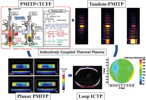
This paper addresses additional recent developments in ICTP after the improvements and developments with high-power semiconductor power supply mentioned above. First, the fundamental principles and applications of modulated induction thermal plasmas are described. Improvement and development have been made to modulated induction thermal plasma (MITP). For example, the amplitude modulation waveform can be not only a pulse waveform but also a given waveform [Citation60,Citation61]. The system and fundamental dynamic behaviors for such modulated induction thermal plasmas are written briefly. Experimentally obtained results indicate that millisecond modulation in the coil current produces a strong disturbance in the radiation intensity of the Ar line and also that the modulation can change the Ar excitation temperature from 5000 to 10,000 K, according to the modulation waveform [Citation58]. Secondly, an example in applications of MITP is presented for high-speed surface nitridation processing [Citation62]-[Citation63]. This example is extremely important because it implies that MITP can involve chemically non-equilibrium effects in behavior of nitrogen atomic density and enthalpy flow. Thirdly, examples in applications of MITP are described on diamond film deposition [Citation64,Citation65]. Because of rapid cooling in thermal plasma, MITP is useful for diamond particle nucleation in the first stage of diamond film deposition. The fourth topic is a new tandem MITP with two coils, which has been established [Citation66,Citation67]. In this case, two coil currents are modulated for temporal and spatial control of the thermal plasma. Using two semiconductor power supplies obtained at reasonable cost, a tandem-MITP can be sustained easily. Fifthly, the latest results for MITP application are presented for some nanoparticle synthesis including new techniques of MITP with time-controlled feeding of the feedstock (TCFF) [Citation68–76]. The MITP+TCFF method is useful to synthesize nanoparticles at a high production rate. Finally, topics will be described for large-area materials processing by thermal plasma [Citation77–81]. For this purpose, some improvements and developments have been made to ICTP torches. Herein, new examples for a planar type ICTP and a loop type ICTP will be introduced.
2. Basic configuration of induction thermal plasmas and their development
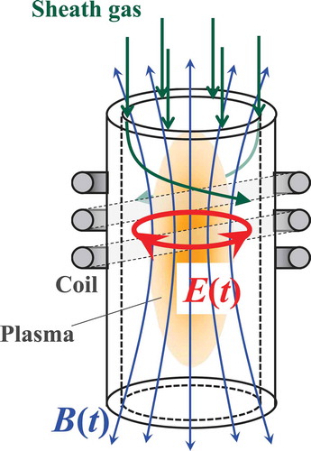
The basic configuration of ICTP was first developed by T. Reed in the 1960s [Citation1]. presents a basic configuration of an inductively coupled thermal plasma (ICTP) torch, which contains a dielectric cylinder tube and a coil surrounding the tube. The radio-frequency (RF) coil current generates the axial magnetic field and an azimuthal electric field in the plasma torch. This electric field accelerates electrons if they are present there, which causes electron impact ionization of gases. Consequently, it generates the plasma, in which azimuthal induced current flows in the plasma to heat itself. At high pressures such as atmospheric pressure, the ICTP is in a thermal plasma condition in which gas temperatures rise up to be almost equal to the electron temperature. Then, the thermal plasma is established with no electrodes, floating in a torch. This configuration is called inductively coupled thermal plasma (ICTP) or induction thermal plasma (ITP). These terms are used herein to distinguish low-pressure inductively coupled plasma (ICP) because this report specifically emphasizes ICP in a thermal plasma state. The ICTP is usually established by high input power from several kilowatts to several hundreds of kilowatts, depending on the operating gas species and the plasma torch size. After some improvements for stable operation and for long life, an ICTP torch with efficient gas flow injection was developed and subsequently commercially distributed. The ICTP presents the following benefits compared to arc plasmas sustained between the electrodes: The ICTP can provide high gas temperature thermal plasma with less impurity. The clean thermal plasma is beneficial for materials processing. The ICTP can produce a larger volume of thermal plasma with lower gas flow velocity. This production can provide longer residence time of the supplied feedstock. The ICTP can be established with various gases such as O2 and N2, which can thereby provide various reaction fields for materials processing. However, the ICTP also has shortcomings. A high-power RF power source is necessary to establish ICTP. Also, RF power sources of several tens of kilowatts are sometimes expensive and bulky. In addition, ICTP is vulnerable to disturbances such as heavy-load feedstock feeding. These cylindrical ICTPs, which have fundamentally similar configurations to Reed’s ICTP, have been widely used for processing of various materials.
Figure 1. Basic configuration of induction thermal plasma
After development of the convectional ICTP, some other configured ICTPs have been developed for new materials processing. As described earlier, several ICTP torches have been developed and improved, such as DC–RF hybrid ICTP torches and RF–RF tandem-ICTP torches, as mentioned in the previous section. These ICP torches have another DC or RF plasma torch on the top of the RF-ICTP torch. After two decades of development, some functionalized ICTPs have also been achieved: one important ICTP is modulated induction thermal plasma (MITP) including pulse-modulated induction thermal plasma (PMITP), arbitrary-waveform modulated induction thermal plasma (AMITP) [Citation60,Citation61], and feedback control modulated induction thermal plasma (FBC-MITP) [Citation82]. The first developed MITP is PMITP, which is sustained by amplitude-modulated RF coil current into a rectangular waveform instead of a fixed amplitude coil current. This modulation in the coil current in milliseconds can perturb temperature and gas flow fields markedly. This result illustrates that coil current modulation can control these fields in thermal plasmas. The RF coil current can be modulated not only into a rectangular waveform but also other given waveforms. This MITP with a given waveform modulated coil current is called arbitrary-waveform modulated induction thermal plasma (AMITP), which was adopted for feed-back control modulated induction thermal plasma (FBC-MITP) to control the thermal plasma temperature to trace a given waveform. Recently, such MITPs have been adopted more and more for processing of different materials. These will be described briefly herein. Moreover, unique ICTPs configured quite differently from the conventional cylindrical ICTP have been developed. These will also be introduced briefly herein.
3. Modulated induction thermal plasmas
3.1. Fundamental principles of modulated induction thermal plasmas (MITP)
To elucidate the modulation of thermal plasma, it is important to understand characteristic times for changing the state in thermal plasmas. Here, characteristic times were estimated in centimeter-class Ar thermal plasmas around 5000 K at atmospheric pressure with typical gas flow velocity of 10–100 m/s [Citation59]. shows the estimated characteristic times in thermal plasmas. Typical characteristic times for thermal conduction, diffusion, and convection were evaluated using the following simple equations:
Table 1. Characteristic times in centimeter-class thermal plasmas at 5000 K at atmospheric pressure
where ,
,
, and
respectively represent the characteristic times for thermal conduction, diffusion, convection and reactions. Also,
denotes the characteristic length,
stands for the mass density,
is the specific heat,
expresses the thermal conductivity,
is the diffusion coefficient,
represents the gas velocity,
is the reaction rate, and
denotes the number density of the plasma. As presented in , thermal conduction, diffusion and convection have similar characteristic times of several milliseconds. Reactions have a wide time range because reactions of various types including ionization, recombination, association and excitation are present in thermal plasmas. However, the radio-frequency (RF) cycle time of the coil current is about 10
–10
s for the coil current frequency of 0.1–10 MHz. This RF cycle time is found to be much shorter than the characteristic times presented above, except reactions, which illustrates that thermal plasma forms statically with almost no macroscopic disturbance by the RF coil current. The modulation cycle time used for modulated thermal plasmas is of approximately milliseconds. This modulation time in milliseconds has a similar order to that of the above characteristic times in thermal plasmas. Therefore, such millisecond modulation of the coil current can markedly perturb even the heavy-particle temperature, gas flow fields, and reaction fields. Furthermore, controlling the modulation amplitude of the coil current and the modulation waveform enables us to control the temperature and gas flow fields in a time domain.
presents an example of the coil current modulated in a triangular–rectangular waveform. Such amplitude-modulation in coil current can be realized using semiconductor RF power supply as represented in [Citation60]. This power circuit contains a DC–DC converter using insulated gate bipolar transistor (IGBT), metal oxide semiconductor field effect transistor (MOSFET) inverter circuit, and impedance matching circuit. This power source is connected through an LC series circuit to the plasma torch. Modulation in this case is achieved by switching IGBT. By contrast, in this power supply, MOSFET elements are switched with a frequency to synchronize a frequency changed by a plasma load using phase-locked loop (PLL) control.
Figure 2. Coil current for modulated induction thermal plasma MITP [Citation60]
![Figure 2. Coil current for modulated induction thermal plasma MITP [Citation60]](/cms/asset/63235b81-120c-47f8-950e-f68e2d439bd7/tapx_a_1867637_f0002_b.gif)
Figure 3. Electric circuit for MITP [Citation60]
![Figure 3. Electric circuit for MITP [Citation60]](/cms/asset/fe4a3ae0-940c-4927-a474-18fe9a9a52f4/tapx_a_1867637_f0003_oc.jpg)
presents an example of (a) the modulation signal, (b) the coil current amplitude, (c) the radiation intensity of the Ar atomic line at 703 nm measured at 10 mm below the coil end, and (d) the Ar excitation temperature there, in a triangular–rectangular waveform modulation case [Citation60]. The input power is 10 kW. The pressure is 5.3 kPa (=40 Torr). The Ar excitation temperature was estimated using the two-line method with the two specified Ar lines at 703 and 714 nm. As shown, the radiation intensity varies periodically following the modulation control signals. The Ar excitation temperature is shown to vary from 5500 K to 7000 K with time following the coil current modulation. This result implies that the Ar excitation temperature in Ar MITP can be controlled in detail using the modulated coil current in milliseconds. This feature of MITP control is expected to be useful for materials processing.
Figure 4. Time evolution in (a) control signal, (b) modulated coil current, (c) radiation intensity, and (d) Ar excitation temperature measured in Ar AMITP [Citation60]
![Figure 4. Time evolution in (a) control signal, (b) modulated coil current, (c) radiation intensity, and (d) Ar excitation temperature measured in Ar AMITP [Citation60]](/cms/asset/a171e489-a1c4-4895-9a1b-846d316c297d/tapx_a_1867637_f0004_b.gif)
Using the developed FBC-MITP system, temperature tracing control tests were conducted for different waveforms [Citation82]. Similar experiments were conducted for other modulation waveforms for temperature control to examine the tracing ability of the FBC-MITP for externally given signals. presents the controlled Ar excitation temperature at a pressure of 55 Torr [Citation82]. Panels (a), (b), (c), and (d) respectively depict the time evolutions in
controlled in rectangular, triangular, sawtooth, and originally produced waveforms at 10 Hz. Results show that the Ar excitation temperature can be changed between 6000 K and 8000 K, almost tracing the reference temperature waveform. In other words, the Ar excitation temperature in thermal plasmas can be controlled quasi-directly in a time domain of approximately milliseconds.
Figure 5. Temperature variation of feedback control type of modulated induction thermal plasma (FBC-MITP): (a) rectangular wave, (b) triangular wave, (c) saw-tooth wave, and (d) originally given waveform at modulation frequency of 10 Hz. The pressure inside the chamber was fixed at 55 Torr [Citation82]
![Figure 5. Temperature variation of feedback control type of modulated induction thermal plasma (FBC-MITP): (a) rectangular wave, (b) triangular wave, (c) saw-tooth wave, and (d) originally given waveform at modulation frequency of 10 Hz. The pressure inside the chamber was fixed at 55 Torr [Citation82]](/cms/asset/c4a6d13d-1931-49e6-906d-5331b5ff317e/tapx_a_1867637_f0005_oc.jpg)
3.2. Application of Ar-N MITP for surface nitridation
There is one example applying Pulse-MITP (PMITP) for surface modification [Citation62,Citation63,Citation83–87]. Here, nitridation processing of the Ti metallic surface using Ar-N PMITP is introduced [Citation62]-[Citation63].
portrays a schematic of the plasma torch, the reaction chamber, and the titanium specimen for nitridation processing. Downstream of this plasma torch, a water-cooled reaction chamber with a specimen holder was installed. On the specimen holder, a 15-mm-diameter, 5-mm-thick titanium specimen was placed and exposed to an Ar-N PMITP at a time-averaged input power of 15 kW. presents high-speed video camera images of the tail part of the Ar-N
PMITP. The gas flow rates of Ar and N
are, respectively, 98 and 2 slpm. The shimmer current level (SCL), which is a ratio of lower current level to higher current level, is 40%. The time increment of the images in this figure is 1.0 ms. As shown in panel (2), the plasma tail extends from the upper side during ‘on-time’. Then, this plasma tail reaches the specimen holder with rotation motion by the supplied swirl gas in panels (2)–(5). By contrast, the plasma tail returns to the upper side in panels (5)–(6) in ‘off-time’. These motions are repeated periodically according to coil current modulation for surface modification. portrays time variation in the radiation intensity of the nitrogen atomic line at 746 nm. As this figure shows, Ar-N
PMITP provides a higher peak value in radiation intensity for larger modulation of the coil current. Furthermore, surface temperature measurements indicate lower temperature for lower SCL, i.e. for larger modulation. The above fact is due to chemically non-equilibrium effect by PMITP [Citation62]-[Citation63]. Nitrogen atoms are produced in high-temperature thermal plasma in the torch during on-time of the coil current modulation, and then they are transported downstream of the torch. During the off-time, the temperature of the thermal plasma decreases with time, and N atoms begin to be associated to produce N
. However, the association reaction of N atoms requires finite time of several tens of milliseconds to reach their equilibrium condition. From this reason, higher N atoms remains there during off-time.
Figure 6. Specimen position for nitridation processing using PMITP [Citation86]
![Figure 6. Specimen position for nitridation processing using PMITP [Citation86]](/cms/asset/6b0cf252-b2d3-4445-9217-0653c88c3533/tapx_a_1867637_f0006_oc.jpg)
Figure 7. Dynamic behavior of the plasma tail. The gas flow rate of Ar/N is 98/2 slpm [Citation86]
![Figure 7. Dynamic behavior of the plasma tail. The gas flow rate of Ar/N 2 is 98/2 slpm [Citation86]](/cms/asset/50b6ad2d-f8c5-4235-a76e-9744af8ffa37/tapx_a_1867637_f0007_oc.jpg)
Figure 8. Time evolution in the radiation intensity of the nitrogen atomic line at 746 nm from Ar-N PMITP [Citation86]
![Figure 8. Time evolution in the radiation intensity of the nitrogen atomic line at 746 nm from Ar-N 2 PMITP [Citation86]](/cms/asset/6728941d-ec04-44c3-86cf-ed240888e906/tapx_a_1867637_f0008_oc.jpg)
The Ti specimen surface irradiated by an Ar-N PMITP was analyzed using X-ray diffraction (XRD) to estimate the current modulation effect on the specimen surface composition. portrays examples of XRD spectra for the specimen surface exposed by Ar-N
PMITP in 5 min. The XRD spectra are apparent for TiN (1 1 1), TiN (1 0 1), and TiN (2 0 0) in all cases. At SCL = 70%, TiN (1 1 1) and TiN (2 0 0) have decreased intensities, whereas TiN (1 0 1) has increased intensity, as well as Ti
N(1 0 1). The appearance of Ti
N illustrates that surface nitridation is insufficient. At still lower SCL of 40%, which corresponds to a larger modulation, the XRD spectra again resemble that at SCL = 100%, in spite of lower surface temperature. Results show that the influence of coil-current modulation apparent in XRD spectra for the irradiated surface, even at the same input power and at the same specimen position.
Figure 9. XRD spectra for specimen surface irradiated by Ar-N PMITP with different shimmer current levels [Citation86]
![Figure 9. XRD spectra for specimen surface irradiated by Ar-N 2 PMITP with different shimmer current levels [Citation86]](/cms/asset/e2d99925-d557-44e6-9bee-f50b18cf58a4/tapx_a_1867637_f0009_b.gif)
3.3. Application of sawtooth-waveform MITP for diamond deposition
Modulated induction thermal plasma is used for polycrystalline diamond film deposition [Citation64,Citation65]. depicts systems used for this work [Citation64]. The plasma torch has a water-cooled metallic tube inserted from the plasma torch head along the center axis. Through this water-cooled metallic tube, CH/H
gas mixture was injected directly to the plasma as a carbon feedstock source. This injected CH
/H
gas mixture was decomposed in the high-temperature region. A Si substrate was placed on the substrate holder made of molybdenum (Mo) at 200 mm below the coil end downstream of the plasma torch. Here, PMITP is adopted for diamond film deposition because PMITP can effectively promote nucleation of diamond particles in rapid cooling during off-time while PMITP also provide high-density atoms and radicals like C
produced by thermal plasma during on-time. The above-mentioned nucleated particles are necessary for polycrystalline diamond film deposition on the first stage.
Figure 10. Schematic diagram of the experimental system [Citation64]
![Figure 10. Schematic diagram of the experimental system [Citation64]](/cms/asset/2a733fb5-3591-4915-8eef-dad0adf7a73f/tapx_a_1867637_f0010_oc.jpg)
shows SEM images of the Si substrate surface irradiated by Ar/CH/H
non-modulated ITP (a) and pulse MITP (b) [Citation64]. As shown in SEM image (a), several particles with grain size of around 0.3 µm were sparsely generated. However, the PMITP irradiation deposits diamond particles more densely on the Si substrate with grain sizes of 1–2 µm. This result indicates that the PM-ITP irradiation promotes diamond particle nucleation on the Si substrate. shows the Raman shift spectra of the deposited one on the Si substrates. Both cases have Raman peaks detected from diamond (at
cm
) and Si (at
cm
) as well as a disordered band (D-band around
cm
) and a graphite band (G-band around
cm
). Especially, the deposited film by PM-ITP irradiation has a larger diamond peak than that obtained from non-modulated ICP irradiation. This result indicates that the PMITP can promote diamond deposition from higher density nucleation of diamond particle and also higher radical density fluxes onto the substrate. Therefore, PM-ITP can be useful in the first state of diamond film deposition.
Figure 11. SEM images of Si substrate surface after irradiation of Ar/CH/H
non-modulated-ITP and PM-ITP [Citation64]
![Figure 11. SEM images of Si substrate surface after irradiation of Ar/CH 4/H 2 non-modulated-ITP and PM-ITP [Citation64]](/cms/asset/f3df95ba-80b6-45fa-a2a8-5b1498bbf167/tapx_a_1867637_f0011_b.gif)
Figure 12. Raman spectra of deposited film on Si substrate irradiated by Ar/CH/H
NM-ITP and PM-ITP [Citation64]
![Figure 12. Raman spectra of deposited film on Si substrate irradiated by Ar/CH 4/H 2 NM-ITP and PM-ITP [Citation64]](/cms/asset/05a7a41f-a594-4048-b6b4-7dd1f0df05e5/tapx_a_1867637_f0012_oc.jpg)
3.4. Applications of PMITP for nanopowder synthesis
The preceding section treated the adoption of MITP to conduct surface modification and deposition, for which control in heat flux and mass flux of atomic particles by the modulated coil current is important. This control might be fundamentally important for nanoparticle synthesis if the modulated induction thermal plasma is used [Citation68,Citation69]. We have developed a method for nanoparticle synthesis called ‘PMITP+TCFF’ method [Citation70–76], incorporating pulse-modulated induction thermal plasma (PMITP) and time-controlled feeding of feedstock (TCFF).
presents our developed methodology for the synthesis of large amounts of nanopowder using PMITP+TCFF method [Citation71]. As described earlier, the PMITP can produce a higher-temperature field and a lower-temperature field repetitively according to the coil current modulation. To this PMITP, the feedstock solid powder is fed directly with Ar carrier gas through a powder feeding tube from the top of the plasma torch head to the PMITP. This feedstock feeding is switched on and off to open and close the feeding valve. The right-hand-side panel of shows a timing chart of the coil current modulation signal, with switching the signal of the feeding valve, and actual feeding of the feedstock powder. Heavy-load feeding of feedstock is necessary to synthesize large amounts of nanopowder. However, plasma extinction, and incomplete evaporation of the feedstock must be avoided. The developed PMITP+TCFF method can overcome this difficulty. The feedstock powder is fed intermittently and synchronously, but only during the high-temperature period in the on-time of the PMITP. This synchronized powder is fed only during the high-temperature period; it can be evaporated during the on-time because of higher power injection to the PMITP. Feeding of the feedstock is stopped by closing the valve during the successive off-time, where the evaporated feedstock material is cooled rapidly because the thermal plasma temperature is decreased because of lower input power. This rapid cooling might promote particle nucleation from evaporated atoms in vapor in the PMITP. Nucleated particles are transported downstream of the PMITP torch with particle growth. In this way, the PMITP+TCFF method can achieve both effective vaporization of the feedstock and support of effective cooling of the evaporated material. It enables synthesis of large amounts of nanopowder with a high production rate.
Figure 13. Method for large-scale nanopowder synthesis using pulse-modulated induction thermal plasma with time-controlled feedstock feeding (PMITP+TCFF) [Citation71]
![Figure 13. Method for large-scale nanopowder synthesis using pulse-modulated induction thermal plasma with time-controlled feedstock feeding (PMITP+TCFF) [Citation71]](/cms/asset/a7c6e716-b828-4484-9fa3-19e4aae7dd6b/tapx_a_1867637_f0013_oc.jpg)
presents some illustrative FE-SEM images of Al-Ti mixture feedstock and the synthesized Al-doped TiO
nanopowder collected at the filter in different SCL conditions [Citation71]. The feedstock feeding rate was 12–19 g/min. Although the feedstock Ti powder has mean diameter of around 27 µm, most of synthesized particles were found to be 100 nm or smaller in the three SCL conditions. After some material analyses, Al
-doped TiO
nanoparticles were synthesized at a production rate of 400 g/h for 80%SCL-70%SCL conditions.
Figure 14. FE-SEM images for () Al-Ti mixture feedstock, and synthesized Al
doped TiO
nanopowder with conditions (
) 80%SCL,
= 12 g min
, (
) 70%SCL,
= 12 g min
, and (
) 60%SCL,
= 19 g min
using PMITP+TCFF method [Citation71]
![Figure 14. FE-SEM images for (a) Al-Ti mixture feedstock, and synthesized Al 3+ doped TiO 2 nanopowder with conditions (b) 80%SCL, gpow = 12 g min −1, (c) 70%SCL, gpow = 12 g min −1, and (d) 60%SCL, gpow = 19 g min −1 using PMITP+TCFF method [Citation71]](/cms/asset/626a0207-e5da-4436-a637-7443d63129e6/tapx_a_1867637_f0014_b.gif)
Another example is synthesis of carbon-coated Si nanoparticles using PMITP+TCFF method [Citation76]. In this case, the Si feedstock is supplied to the PMITP; also, the Ar+CH gas mixture was injected downstream of the PMITP. portrays TEM images of the synthesized nanoparticles. As this figure shows, graphene-encapsulated Si nanoparticles were synthesized at a high production rate.
Figure 15. TEM images of synthesized Si/C particles using PMITP+TCFF method [Citation76]
![Figure 15. TEM images of synthesized Si/C particles using PMITP+TCFF method [Citation76]](/cms/asset/66555949-b253-4dcc-9b53-419bccaf9ebd/tapx_a_1867637_f0015_oc.jpg)
4. Tandem-type modulated induction thermal plasma
The combination of two MITPs produces another MITP with controllability in temperature and gas flow fields: a tandem MITP. The tandem-MITP can be realized using two RF power sources with different frequencies at reasonable prices. depicts a schematic diagram of the tandem type of modulated induction thermal plasma (Tandem-MITP) system [Citation66,Citation67]. The tandem-MITP is sustained by two RF power supplies: an RF power supply for the upper coil and an RF power supply for the lower coil. They have different driving frequencies between them to avoid electric circuit coupling. They can also modulate the coil current amplitude. presents the dynamic behavior of a Tandem-MITP for phase difference in the current modulation for the upper coil and for the lower coil. The images were recorded using a high-speed video camera. Timing
here represents the time from transition from the lower current level to the higher current level for the upper coil. As this figure shows, high light intensity plasma is present in the upper-coil region at
=4 ms. This plasma flows into the lower-coil region at
=12.5 ms. At
=30 ms, plasma exists only in the lower-coil region. In this way, the plasma can be transported from the upper to the lower coil regions. Therefore, MITP is controlled temporally and spatially. Tandem-MITP is useful for advanced materials processing. Actually, tandem-MITP is being studied for adoption in processing for nanoparticle synthesis.
Figure 16. Schematic showing the tandem type of modulated induction thermal plasma (Tandem-MITP) system [Citation66]
![Figure 16. Schematic showing the tandem type of modulated induction thermal plasma (Tandem-MITP) system [Citation66]](/cms/asset/c036b388-28f7-45cb-8870-4734d7b27f0b/tapx_a_1867637_f0016_oc.jpg)
Figure 17. High-speed video images showing Tandem-MITP for phase difference between the upper and lower coil current [Citation66]
![Figure 17. High-speed video images showing Tandem-MITP for phase difference θd=π between the upper and lower coil current [Citation66]](/cms/asset/9c0c7820-52f9-4096-97ba-4e46eb7e30aa/tapx_a_1867637_f0017_oc.jpg)
5. Planar type induction thermal plasma
Conventional cylindrical torches are only suitable to a slight degree for large-area material processing because thermal plasma in the cylindrical quartz tube shrinks as a result of the Lorentz force. For this reason, planar-type ICTP torches have been developed for large-area materials processing [Citation77]-[Citation79].
shows the configuration of the planar-ICTP torch [Citation77]. The planar-ICTP has a rectangular quartz vessel and an RF coil sandwiching this vessel. The RF coil current generates a magnetic field perpendicular to this rectangular quartz vessel and then generates a rotational RF electric field in the vessel. The RF electric field in rotational direction produces a thin donut-type thermal plasma in the vessel. The thermal plasma jet ejects out the outlet of the vessel if gas is injected from the top of the vessel. This ejected thermal plasma is useful for irradiation to a substrate located near the vessel outlet. In addition, two-dimensional processing of the substrate surface can be conducted if the substrate is swept perpendicularly to the vessel. A substrate holder made of SiN
is placed inside the rectangular vessel at a distance of 10 mm from the downer base edge of the vessel, as presented in . In this system, Ar gas is injected from the head of the quartz torch along the four walls as a sheath gas resembling a curtain, whereas O
gas is injected as precipitation through a mesh from the top of the torch. portrays visible light emissions from a planar Ar-O
ICTP at 20 Torr with a Si
N
substrate holder and with different Ar gas flow rates for the long-sides, recorded using a high-speed video camera. An RF power inverter source was used with a 357 kHz driving frequency. The output power from the source was fixed at 7 kW. As shows, the ICTP is sustained with a ring shape along the coils in the torch. It is also apparent that the lower side of the ICTP is formed on the Si
N
substrate holder. This lower side of the ICTP is useful for surface modification. Actually, the oxide layer was formed on the Si substrate with around 150 nm thickness after only 10 min irradiation of a planar Ar-O
ICTP.
Figure 18. Experimental setup of a planar ICTP torch with SiN
substrate: (a) front and (b) side [Citation77]
![Figure 18. Experimental setup of a planar ICTP torch with Si 3N 4 substrate: (a) front and (b) side [Citation77]](/cms/asset/94f6e00e-cf9a-4e2e-80ff-fbf4e566e294/tapx_a_1867637_f0018_oc.jpg)
Figure 19. Visible light emission from Ar/O planar ICTP at 7 kW and 20 Torr with a fixed Ar gas flow rate of 4 slpm into the short-sides. The O
gas flow rate was 0.1 slpm. Only the Ar gas flow rates into the long-sides were changed: (a) (4 +4)/0.1, (b) (4 +6)/0.1, (c) (4 +8)/0.1, and (d) (4 +10)/0.1 slpm [Citation77]
![Figure 19. Visible light emission from Ar/O 2 planar ICTP at 7 kW and 20 Torr with a fixed Ar gas flow rate of 4 slpm into the short-sides. The O 2 gas flow rate was 0.1 slpm. Only the Ar gas flow rates into the long-sides were changed: (a) (4 +4)/0.1, (b) (4 +6)/0.1, (c) (4 +8)/0.1, and (d) (4 +10)/0.1 slpm [Citation77]](/cms/asset/9b56d755-5c17-411e-aacb-43dc00f68eb3/tapx_a_1867637_f0019_oc.jpg)
6. Loop-type inductively coupled thermal plasmas
Another type of ICTP developed for large-area materials processing is loop-ICTP [Citation80]–[Citation81]. presents the schematic diagram of loop type inductively coupled thermal plasma (Loop-ICTP) torch. In this loop-ICTP method, the ICTP is sustained inside the loop quartz tube. A part of the loop thermal plasma formed lines with a linear shape on the substrate directly. This linear thermal plasma exposure to the substrate makes it possible to provide long-area materials processing such as long-area surface modification in a one-dimensional (1D) direction. Scanning the substrate in another direction perpendicular to the linear thermal plasma offers large-area materials processing in a two-dimensional (2D) area.
Figure 20. Loop-type inductively coupled thermal plasma (Loop-ICTP) torch [Citation81]
![Figure 20. Loop-type inductively coupled thermal plasma (Loop-ICTP) torch [Citation81]](/cms/asset/b98dedc9-09e4-45dc-941f-50801d768507/tapx_a_1867637_f0020_oc.jpg)
) presents visible light emissions from Ar/O loop-ICTP inside the loop tube and on the substrate during oxidation processing. The pressure was set to 10 Torr, 15 Torr, and 20 Torr. The input power was fixed at 5 kW. The fundamental frequency of the coil current was 304 kHz. The Ar gas was supplied with a 0.5 L/min gas flow rate, whereas O
gas was fed with a 0.2 L/min gas flow rate. As shown in the figure, the loop ICTP is formed inside the loop-tube and also on the substrate. Because of O
injection only on the substrate, the loop-ICTP, red light is emitted from the oxygen atomic line. Using this loop-ICTP and sweeping the substrate, two-dimensional (2D) surface oxidation was conducted for the Si substrate. ) presents 2D distributions of the oxide layer thickness fabricated on a Si substrate surface after exposure of the loop-ICTP with scanning speed of 0.25 mm/s. This figure presents the whole surface oxidized by sweeping loop-ICTP for only 200 s.
Figure 21. Visible light emission of loop-ICTP (a) and 2D distributions of oxide layer thickness (b) fabricated on Si substrate surface at pressures of 20 Torr [Citation81]
![Figure 21. Visible light emission of loop-ICTP (a) and 2D distributions of oxide layer thickness (b) fabricated on Si substrate surface at pressures of 20 Torr [Citation81]](/cms/asset/85f804ae-1116-4c4e-9934-12ac42f8c1a9/tapx_a_1867637_f0021_oc.jpg)
7. Conclusion
This review described recent developments of inductively coupled thermal plasma (ICTP) for materials processing. The various modes of ICTP present several benefits of high enthalpy and high radical density, which are beneficial for high-speed materials processing. However, the various methods are still under study for additional control of high-temperature and chemical active fields. For these purposes, ICTP continues to be improved, with continual development of new ICTPs. One important development is modulated induction thermal plasma (MITP), which is sustained by amplitude-modulated coil current. The modulation in coil current can perturb temperatures and gas flow fields in thermal plasmas, and can control them. Several recent applications of MITP have been made to surface modification, deposition, and nanoparticle synthesis. These are all unique applications in materials processing. Other developments are planar-ICTP and loop-ICTP, which have both been developed to be used instead of the conventional cylindrical ICTP for large-area materials processing. New induction thermal plasma methods will be developed further with more functionalization for the construction of a future sustainable society.
Disclosure statement
No potential conflict of interest was reported by the author.
Additional information
Funding
References
- Reed TB. Induction–coupled plasma torch. J Appl Phys. 1961;32(5):821–27.
- Fazekas P, Czegeny Z, Mink J, et al. Decomposition of poly(vinyl chloride) in inductively coupled radiofrequency thermal plasma. Chem Eng J. 2016;302:163–171.
- Darthout E, Gitzhofer F. Structure stabilization by zirconia pinning effect of Y2Si2O7 environmental barrier coatings synthesized by solution precursor plasma spraying process. Surf Coat Technol. 2017;309:1081–1088.
- Darthout E, Gitzhofer F. Thermal cycling and high-temperature corrosion tests of rare earth silicate environmental barrier coatings. J Therm Spray Technol. 2017;26(8):1823–1837.
- Major K, Veilleux J, Brisard G. Lithium iron phosphate powders and coatings obtained by means of inductively coupled thermal plasma. J Therm Spray Technol. 2016;25(1–2):357–364.
- Berghaus JO, Meunier JL, Gitzhofer F. Monitoring and control of RF thermal plasma diamond deposition via substrate biasing. Meas Sci Technol. 2004;15:161–164.
- Matsumoto S, Hino M, Kobayashi T. Synthesis of diamond films in an rf induction thermal plasma. Appl Phys Lett. 1987;51:737–739.
- Wang C, Inazaki A, Shirai T, et al. Effect of ambient gas and pressure on fullerene synthesis in induction thermal plasma. Thin Solid Films. 2003;425:41–48.
- Todorovic-Markovic B, Markovic Z, Mohai I, et al. Efficient synthesis of fullerenes in RF thermal plasma reactor. Chem Phys Lett. 2003;378:434–439.
- Park J-Y, Park KB, Kang J-W, et al. Spheroidization behavior of water-atomized 316 stainless steel powder by inductively coupled thermal plasma. Mater Today Commun. 2020;25:101488.
- Yu C, Zhou X, Wang D, et al. Study on the RF inductively coupled plasma spheroidization of refractory W and W-Ta alloy powders. Plasma Sci Technol. 2018;20(1):014019.
- Tong JB, Lu X, Liu CC, et al. Numerical simulation and prediction of radio frequency inductively coupled plasma spheroidization. Appl Therm Eng. 2016;100:1198–1206.
- Lee M-Y, Kim J-S, Seo J-H. Radio-frequency thermal plasma synthesis of nano-sized indium zinc tin oxide powders with reduced indium content. Thin Solid Films. 2012;521:60–64.
- Lee M-Y, Song M-K, Kim J-S, et al. 2014 Synthesis of single-phase Gd-doped ceria nanopowders by radio frequency thermal plasma treatment. J Am Ceram Soc. 2014;97(5):1379–1382.
- Boselli M, Ceschini L, Colombo V, et al. Cast Al-based nanocomposites reinforced with thermal plasma synthesized ceramic nanoparticles. Mater Sci Forum. 2014;783-786:1567–1572.
- Han C, Na H, Kim Y, et al. In-situ synthesis of tungsten nanoparticle attached spherical tungsten micro-powder by inductively coupled thermal plasma process. Int J Refract Metals Hard Mater. 2015;53:7–12.
- Na H, Lee W, Choi H. Characteristics of Ni-W bimetallic nanoparticle via reactive RF thermal plasma synthesis. Int J Refract Metals Hard Mater. 2015;53:17–22.
- Dhamale GD, Mathe VL, Bhoraskar SV, et al. Synthesis and characterization of Nd2O3 nanoparticles in a radiofrequency thermal plasma reactor. Nanotechnology. 2016;27(8):085603.
- Bianconi S, Boselli M, Gherardi M, et al. Numerical investigation of the joint impact of thermophoresis and radiative losses in induction plasma synthesis of copper nanoparticles. J Phys D Appl Phys. 2017;50(16):165204.
- Zhao X, Chen HY, Shu CY, et al. Synthesis and characterization of Si3N4 nanopowder by RF induction thermal plasma. Mater Sci Forum. 2017;898:1597–1602.
- Kim K-H, Choi H, Han C. Tungsten micropowder/copper nanoparticle core/shell-structured composite powder synthesized by inductively coupled thermal plasma process, metallurgical and materials transactions A. Phys Metallurgy Mater Sci. 2017;48(1):439–445.
- Dhamale GD, Tak AK, Mathe VL, et al. Nucleation and growth of Y2O3 nanoparticles in a RF-ICTP reactor: A discrete sectional study based on CFD simulation supported with experiments. J Phys D Appl Phys. 2018;51(25):255202.
- Oh J-W, Na H, Cho YS, et al. In situ synthesis of bimetallic tungsten-copper nanoparticles via reactive radio-frequency (RF) thermal plasma. Nanoscale Res Lett. 2018;13(220). DOI:https://doi.org/10.1186/s11671-018-2623-1
- Zhang X, Hayashida R, Tanaka M, et al. Synthesis of carbon-coated silicon nanoparticles by induction thermal plasma for lithium ion battery. Powder Technol. 2020;371:26–36.
- Arabzadeh Esfarjani S, Mostaghimi J, Kim KS, et al. Radio frequency thermal plasma: the cutting edge technology in production of single-walled carbon nanotubes. J Therm Sci Tech. 2011;6(2):307–322.
- Kim KS, Kingston CT, Ruth D, et al. Synthesis of high quality single-walled carbon nanotubes with purity enhancement and diameter control by liquid precursor Ar-H2 plasma spraying. Chem Eng J. 2014;250:331–341.
- Kim KS, Couillard M, Shin H, et al. Role of hydrogen in high-yield growth of boron nitride nanotubes at atmospheric pressure by induction thermal plasma. ACS Nano. 2018;12(1):884–893.
- Li J, Hu R, Qu H, et al. Radio-frequency thermal plasma-induced novel chainmail-like core–shell MoO2 as highly stable catalyst for converting syngas to higher alcohols. Appl Catal B Environ. 2019;249:63–71.
- Takigawa A, Kim T-H, Igami Y, et al. Formation of transition alumina dust around asymptotic giant branch stars: condensation experiments using induction thermal plasma systems. Astrophys J Letters. 2019;878(1):L7.
- Boulos MI. Heating of powders in the fire ball of an induction plasma. IEEE Trans Plasma Sci. 1978;6(2):93–106.
- Boulos MI. The inductively coupled r.f. (radio frequency) plasma. Pure Appl Chem. 1985;57(9):1321–1352.
- Mostaghimi J, Proulx P, Boulos MI. An analysis of the computer modeling of the flow and temperature fields in an inductively coupled plasma. Numerical Heat Transfer. 1985;8(2):187–201.
- Proulx P, Mostaghimi J, Boulos MI. Plasma–particle interaction effects in induction plasma modeling under dense loading conditions. Int J Heat Mass Transfer. 1985;28(7):1327–1336.
- Mostaghimi J, Proulx P, Boulos MI. A two-temperature model of the inductively coupled rf plasma. J Appl Phys. 1987;61(5):1753–1760.
- Proulx P, Mostaghimi J, Boulos MI. Heating of powders in an r.f. inductively coupled plasma under dense loading conditions. Plasma Chem Plasma Process. 1987;7(1):29–52.
- Mostaghimi J, Boulos MI. Two-dimensional electromagnetic field effects in induction plasma modelling. Plasma Chem Plasma Process. 1989;9(1):25–44.
- Boulos MI. Thermal Plasma Processing. IEEE Trans Plasma Sci. 1991;19(6):1078–1089.
- Boulos MI. RF induction plasma spraying: state-of-the-art review. J Therm Spray Technol. 1992;1(1):33–40.
- Boulos MI. The inductively coupled radio frequency plasma. High Temperature Material Processes. 1997;1(1):17–39.
- Ye R, Proulx P, Boulos MI. Turbulence phenomena in the radio frequency induction plasma torch. Int J Heat Mass Transfer. 1999;42(9):1585–1595.
- Xue S, Proulx P, Boulos MI. Extended-field electromagnetic model for inductively coupled plasma. J Phys D Appl Phys. 2001;34(12):1897–1906.
- Mostaghimi J, Boulos MI. Thermal plasma sources: how well are they adopted to process needs? Plasma Chem Plasma Process. 2015;35(3):421–436.
- Yoshida T, Tawi T, Nishimura H, et al. Characterization of a hybrid plasma and its application to a chemical synthesis. J Appl Phys. 1983;54:640–646.
- Tani T, Yoshida T, Akashi K. Synthesis of ultrafine Si3N4 in a hybrid plasma, Yogyo Kyokai Shi. J Ceram Soc Jpn. 1986;94(1):1–6.
- Lee HJ, Eguchi K, Yoshida T. Preparation of ultrafine silicon nitride, and silicon nitride and silicon carbide mixed powders in a hybrid plasma. J Am Ceram Soc. 1990;73(11):3356–3362.
- Eguchi K, Yoshida T. Size distribution of SiC powders synthesized in hybrid plasma. J Mater Sci Lett. 1993;12(11):858–861.
- Nomoto N, Okazaki Y, Kuroda K, et al. Integrated fabrication process for solid oxide fuel cells using hybrid plasma spraying. High Temperature Material Processes. 1997;1(1):pp.41–47.
- Uesugi T, Nakamura O, Yoshida T, et al. A tandem radio-frequency plasma torch. J Appl Phys. 1988;64:3874–3879.
- Boulos MI, Jurewicz J, 2004 Multi-coil induction plasma torch for solid-state power supply, US patent 6, 693, 253, 17 Feb.
- Boulos MI, Jurewicz J, 2005 Multi-coil induction plasma torch for solid-state power supply, US patent 6, 919, 527, 19 July
- Dresvin SV. Physics and technology of low temperature plasmas. Iowa, USA: Iowa State University Press; 1977.
- Alavi S, Mostaghimi J, Novel A. ICP torch with conical geometry. Plasma Chem Plasma Process. 2019;39(2):359–376.
- Ishigaki T, Xiaobao F, Sakuta T, et al. Generation of pulse-modulated induction thermal plasma at atmospheric pressure. Appl Phys Lett. 1997;71:3787–3789.
- Sakuta T, Ishigaki T. Non-equilibrium effects in pulse modulated induction thermal plasma for advanced material processing. Pure Appl Chem. 1999;71:1845–1852.
- Tanaka Y, Sakuta T. Measurement of dynamic response time in pulse modulated thermal plasma. Trans Mater Res Soc Jpn. 2000;25:293–296.
- Sakuta T, Tanaka Y, Hashimoto Y, et al. Novel system of an inductively coupled thermal plasma with pulse amplitude modulation of electromagnetic field. Electr Eng Jpn. 2002;138:26–33.
- Tanaka Y, Sakuta T. Stable operation region and dynamic behavior of pulse modulated Ar thermal plasma with different molecular gases. Electr Eng Jpn. 2003;143:1–11.
- Tanaka Y, Sakuta T. Temperature control of Ar induction thermal plasma with diatomic molecular gases by pulse-amplitude modulation of coil-current. Plasma Sources Sci Technol. 2003;12:69–77.
- Tanaka Y. Time-dependent two-temperature chemically non-equilibrium modelling of high-power Ar-N2 pulse-modulated inductively coupled plasmas at atmospheric pressure. J Phys D: Appl Phys. 2006;39:307–319.
- Tanaka Y, Morishita Y, Okunaga K, et al. Generation of high-power arbitrary-waveform modulated inductively coupled plasmas for materials processing. Appl Phys Lett. 2007;90:071502.
- Tsubokawa Y, Tanaka Y, Uesugi Y. Control of induction thermal plasmas by coil current modulation in arbitrary-waveform. J Plasma Fusion Res Series. 2009;8:1353–1357.
- Tanaka Y, Muroya T, Hayashi K, et al. Simultaneous control of numerical enhancement of N atom and decrease in heat flux into reaction chamber using Ar-N2 pulse-modulated induction thermal plasmas. Appl Phys Lett. 2006;89:031501.
- Tanaka Y, Hayashi K, Nakamura T, et al. Influence of ontime on increased number density of excited nitrogen atom in pulse modulated induction thermal plasmas. J Phys D: Appl Phys. 2008;41:185–203.
- Betsuin T, Tanaka Y, Arai T, et al. Influence of coil current modulation on polycrystalline diamond film deposition by irradiation of Ar/CH4/H2 inductively coupled thermal plasmas. J Phys D Appl Phys. 2018;51:095601.
- Hata K, Tanaka Y, Nakano Y, et al. Polycrystalline diamond film fabrication using modulated inductively coupled thermal plasmas at different pressure conditions. J Appl Phys. 2019;126:223302.
- Kuraishi K, Akao M, Tanaka Y, et al. Temperature behavior in a tandem type of modulated induction thermal plasma for materials processing. J Phys Conf Ser. 2013;441:012016.
- Onda K, Tanaka Y, Akashi K, et al. Numerical thermofluid simulation on tandem type of inductively coupled thermal plasmas with and without current modulation in a lower coil. J Physics D: Appl Physics. 2020;53(16):165201.
- Tanaka Y, Nagumo T, Sakai H, et al. Nanoparticle synthesis using high-powered pulse-modulated induction thermal plasma. J Phys D: Appl Phys. 2010;43:265201.
- Tanaka Y, Sakai H, Tsuke T, et al. Influence of coil current modulation on TiO2 nanoparticle synthesis using pulse-modulated induction thermal plasmas. Thin Solid Films. 2011;519(20):7100–7105.
- Tanaka Y, Tsuke T, Guo W, et al. A large amount synthesis of nanopowder using modulated induction thermal plasmas synchronized with intermittent feeding of raw materials. J Phys Conf Ser. 2012;406:012001.
- Kodama N, Tanaka Y, Kita K, et al. A method for large-scale synthesis of Al-doped TiO2 nanopowder using pulse-modulated induction thermal plasmas with time-controlled feedstock feeding. J Phys D: Appl Phys. 2014;47:195304.
- Kodama N, Tanaka Y, Kita K, et al. Spatiotemporal distribution of thermal plasma temperature and nucleation process in the torch during TiO2 nanopowder synthesis. Plasma Sources Sci Technol. 2017;26(7):075008.
- Ishisaka Y, Kodama N, Kita K, et al. High-rate synthesis of Si nanowires using modulated induction thermal plasmas. Appl Phys Express. 2017;10:096201.
- Kodama N, Tanaka Y, Ishisaka Y, et al. Spatial distribution of Ti vapor admixture ratio in ar induction thermal plasma torch during Ti feedstock injection. Jpn J Appl Phys. 2018;57(3):036101.
- Kambara M, Hamazaki S, Kodama N, et al. Efficient modification of Si/SiOz nanoparticles by pulse-modulated plasma flash evaporation for an improved capacity of lithium-ion storage. J Phys D: Appl Phys. 2019;52:325502.
- Tanaka Y, Shimizu K, Akashi K, et al. High rate synthesis of graphene-encapsulated silicon nanoparticles using pulse-modulated induction thermal plasmas with intermittent feedstock feeding. Jpn J Appl Phys. 2020;59:SHHE07.
- Tial MKS, Irie H, Maruyama Y, et al. Fundamentals of planar-type inductively coupled thermal plasmas on a substrate for large-area material processing. Jpn J Appl Phys. 2016;55(7S2):07LB03.
- Tial MKS, Tanaka Y, Akao M, et al. Fundamental properties of a planar type of inductively coupled thermal plasmas with current modulation. J Phys D Appl Phys. 2016;49:385204.
- Tial MKS, Tanaka Y, Maruyama Y, et al. Uniform surface oxidation of an si substrate by a planar modulated inductively coupled thermal plasma with molecular gas feed. Plasma Chem Plasma Process. 2017;37(3):857–876.
- Maruyama Y, Tanaka Y, Irie H, et al. Rapid surface oxidation of the Si substrate using longitudinally long Ar/O2 loop type of inductively coupled thermal plasmas. IEEE Trans Plasma Sci. 2016;44(12):3164–3171.
- Tsuchiya T, Tanaka Y, Maruyama Y, et al. Loop type of inductively coupled thermal plasmas system for rapid two-dimensional oxidation of Si substrate surface. Plasma Chem Plasma Process. 2018;38(3):599–620.
- Tanaka Y, Tsubokawa Y, Uesaka Y, et al. Development of a quasi-direct temperature control system of modulated induction thermal plasmas for advanced materials processing. Plasma Sources Sci Technol. 2013;22:065016.
- Ishigaki T, Haneda H, Okada N, et al. Surface modification of titanium oxide in pulse-modulated induction thermal plasma. Thin Solid Films. 2001;390:20–25.
- Ohashi N, Ishigaki T, Okada N, et al. Effect of hydrogen doping on ultraviolet emission spectra of various types of ZnO. Appl Phys Lett. 2002;80:2869–2871.
- Ohashi N, Ishigaki T, Okada N, et al. Passivation of active recombination centers in ZnO by hydrogen doping. J Appl Phys. 2003;93:6386–6392.
- Tanaka Y, Uesugi Y, Sakuta T. Controlling the number of excited atoms flowing into the reaction chamber using pulse-modulated induction thermal plasmas at atmospheric pressure. Plasma Sources Sci Technol. 2007;16:281–289.
- Tanaka Y, Muroya T, Hayashi K, et al. Control of nitrogen atomic density and enthalpy flow into reaction chamber in Ar-N2 pulse-modulated induction thermal plasmas. IEEE Trans Plasma Sci. 2007;35(2):197–203. Part 1.