
 ?Mathematical formulae have been encoded as MathML and are displayed in this HTML version using MathJax in order to improve their display. Uncheck the box to turn MathJax off. This feature requires Javascript. Click on a formula to zoom.
ABSTRACT
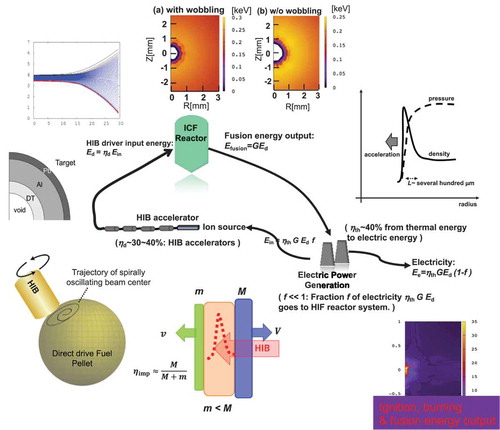
Direct-drive heavy ion beam (HIB) inertial confinement fusion (ICF), or HIF would be a promising future energy source for society. Particle accelerators produce HIBs with precise particle energies, pulse lengths and pulse shapes with high energy efficiencies of ~30-40%. Higher energy driver efficiency means that a lower fusion energy output is required to construct a HIF power station to supply ~1 GW of electricity. A HIF power station could use about 4 to 5 MJ of HIB energy per shot at a shot rate of ~10 Hz. This review is focused on the direct-drive scheme in HIF. In direct-drive fuel target HIBs deposit their energy into a shell surrounded by a denser tamping outer layer. The DT (Deuterium-Tritium) fusion fuel, with a total mass of several mg, must be compressed to about one thousand times solid density to reduce the input driver energy and to achieve an adequate burn fraction. High-density compression is a major challenge in ICF, requiring that non-uniformity in driver energy deposition be kept lower than a few percent. The axis of an HIB can be made to oscillate sufficiently rapidly to improve the uniformity of energy deposition.
Graphical abstract
1. Introduction
Nuclear fusion would be a future energy source for society [Citation1–3]. In nuclear fusion major schemes are magnetic confinement fusion (MCF) [Citation1,Citation2,Citation4–7] and inertial confinement fusion (ICF) [Citation2,Citation3,Citation8–11]. In this review article, we focus on direct-drive ICF based on heavy ion beam (HIB) [Citation11–16]. In direct-drive HIB ICF (HIF), HIBs illuminate directly the surface of the fusion fuel spherical capsule. On the other hand, in indirect-drive ICF, the driver beams’ energy is converted first to radiation, and the radiation drives the fuel capsule [Citation3,Citation10].
In Ref [Citation11], we have reviewed HIF physics in 2016, and it was oriented to specialists in HIF. After that, new remarkable scientific advances have been achieved in HIF studies, including ion source in accelerators, accelerator science, cluster ion beam science and technology, beam manipulation science, control of fuel target injection, instability control by heavy ion beam, fuel target uniformity mitigation, etc. The present review paper is prepared to present the overall achievements to date in HIF studies in a concise manner for scientists not only in HIF but also in other disciplines.
HIB has favorable characteristics to construct nuclear fusion power plant. HIB is generated by accelerator [Citation12,Citation16–23], and the energy efficiency of HIB accelerators is relatively high, specifically ~30-40% from electricity to HIB particle energy. The energy efficiency is called driver efficiency in ICF. Accelerators also have a flexibility to control the HIB parameters, for example, focusing position, beam focal radius, particle energy distribution in a beam, ion energy, pulse length, pulse shape, HIB axis oscillation/wobbling motion, operating repetition rate, etc [Citation12,Citation16–26]. Another important preferable feature is to deposit HIB energy inside a material. The interaction of HIB ions with materials is almost classical, that is, the Coulomb interaction [Citation27–30]. This means that HIB ion interaction is well understood and defined inside materials. The energy deposition spatial profile in materials is sufficiently predictable, and the fusion fuel design would be relatively simple [Citation11,Citation31].
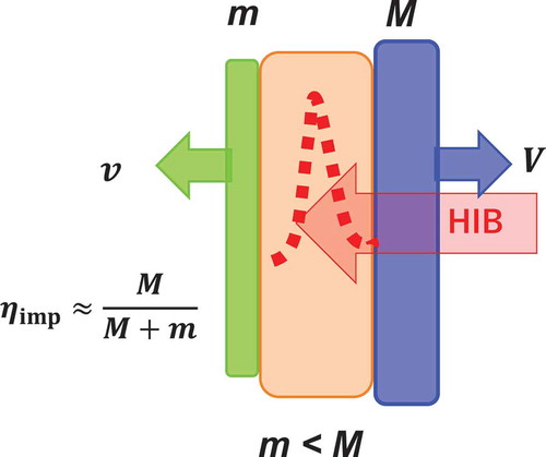
Heavy ions may penetrate a thin heavy tamping layer, and deposit the particle energy near the stop position inside the material beyond the heavy layer. shows a schematic figure of this energy deposition profile in the middle layer by a dotted red curve in . Near the ion stop region, the Coulomb collision becomes strong [Citation27–30], and the HIB energy deposition peak appears in the inner region as shown in . If the mass of the middle layer and the thermal energy of the materials are negligible, the input HIB energy is transferred to the kinetic energy of both the right layer
and the left layer
. Based on the energy conservation and the momentum balance, the energy efficiency
is obtained by
The energy efficiency
shows the ratio of the kinetic energy
of the left layer and the input driver energy
. In ICF,
is implosion efficiency. When the right heavy mass
becomes large, the efficiency
becomes large. In HIF direct-drive fuel target is designed to follow this fact to realize a high implosion efficiency
.
Figure 1. HIB illuminates a three-layer target from the right in this example. The interaction of beam ions with materials is almost explained by the Coulomb collision, and the HIB energy deposition profile shown by a dotted red line has a peak (the Bragg peak) near the stop region. In Figure 1 the heavy ions stop in the middle layer. When, the energy conversion becomes efficient:
In this example, we ignore the mass of the middle layer and the thermal energy in the materials
Driver efficiency determines a requirement for fusion energy gain
. Fusion energy gain
is defined by fusion energy output
divided by input driver energy
. The high HIB driver efficiency
of ~30-40% allows a lower fusion gain to construct a fusion power plant. shows energy balance in ICF reactor systems. In the driver system is assumed to be HIB accelerators, though the overall system is common in ICF. The electric energy
goes to accelerators to generate HIBs
with the driver efficiency
. ICF fuel target releases fusion energy output
.
Figure 2. Energy cycle of ICF reactor system. In Figure 2, energy driver is assumed to be HIB accelerators, though the overall system is general in ICF
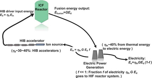
The thermal energy is converted to electricity
with efficiency
. A fraction
of electricity
is recirculated to accelerators:
. The rest of electricity
is supplied to our society. The high driver efficiency relaxes the fusion energy gain requirement to construct a fusion power plant, which delivers ~1 GW of electricity to society [Citation11].
The flexibility of HIB accelerators relaxes the requirements for driver HIB parameters in order to deliver sufficient fusion energy output. For example, HIB axis can be made to oscillate with a high frequency, for example, ~several hundred MHz – 1 GHz. The HIB axis oscillation or wobbling behavior helps reduce HIBs illumination non-uniformity on a fusion fuel target. The D (deuterium)-T (tritium) fusion fuel should be compressed to about a thousand times solid density to reduce the input driver energy and to achieve an adequate burn fraction [Citation2,Citation3]. The idea of the hollow sphere implosion and fuel compression was proposed in Refs. [Citation8,Citation32]. First the driver energy deposited is effectively converted to the kinetic energy of the imploding DT fuel. ) shows an example structure of a hollow shell fuel target in HIF. The spherical target outer radius would be several mm. Near the target center, the imploding DT fuel is stagnated and compressed. The DT fuel kinetic energy is converted to the DT fuel thermal energy, and the DT fuel is ignited. In order to reach the high density, the fuel target implosion non-uniformity should be kept lower than a few percent [Citation2,Citation3,Citation33,Citation34]. The implosion non-uniformity of spherical fuel target comes from driver illumination non-uniformity, imperfect sphericity of fuel target, target injection alignment error into a fusion reactor, etc [Citation35–41]. The high-density fuel compression is a major challenge in ICF. HIB accelerators also provide a unique feature of the HIB axis wobbling behavior, which mitigates the HIBs illumination non-uniformity [Citation11,Citation31,Citation42,Citation43]. Multiple driver beams irradiate an ICF fuel target. The HIB illumination scheme is important to obtain a uniform energy deposition on fuel target material [Citation44–46].
In Section 2, the concept of heavy ion inertial fusion (HIF) is presented, and the characteristics of HIF are introduced. The present international research projects are also introduced, relating to HIF and high energy density physics (HEDP) based on HIB. Section 3 summarizes the heavy ion interaction with materials. The HIBs illumination scheme is also discussed. In Section 4 application topics relating to HEDP based on HIB are introduced briefly. Section 5 is devoted to describe HIF energy release from fuel target. In this review we focus on direct-drive spherical target in HIF. In Section 6 we conclude the HIF study review.
2. Concept and characteristics of heavy ion inertial fusion
Research projects are first presented in HIF and HIB-based HEDP researches. The FAIR (Facility for Antiprotons and Ion Research) project has been started at Darmstadt, Germany [Citation19]. FAIR is oriented to basic physics to understand the structure of matter, the evolution of the universe, etc., including HIF, HEDP and plasma physics. At Berkeley, CA, U. S. A. an experimental device NDCX II works on HIB accelerator physics including HIB space charge neutralization [Citation18,Citation47]. The HIAF (High Intensity heavy ion Accelerator Facility) project in China has been planned for HIF and HEDP studies [Citation20–22,Citation48–50]. HIAF construction started in 2018 in Huizhou City, China. The maximum energy and power in one beam pulse could reach 100 kJ and 1 TW, respectively. With the high power of the heavy ion beam, a large volume of a material would be heated to ~10 eV [Citation21,Citation49,Citation50]. Researches on HIF have been conducted at a large number of research labs and universities in Japan, Germany, China, France, U.S.A., Russia, Italy, Spain, Kazakhstan, etc. [Citation11,Citation12,Citation16,Citation51].
Now the concept and characteristics of HIF and HIB are presented. When HIF reactor system is focused, one of the merits of HIF would be the high driver efficiency as presented in the introduction. In one can easily derive a relation of a requirement for the fusion energy gain
, to sustain the fusion power plant:
. The electricity generation efficiency
would be ~40% from thermal energy to electricity. The fraction
of electricity generated goes to operate the HIF system, and
should be smaller than 1. The HIB accelerator driver efficiency
is ~30-40% from electricity to the HIB particle energy. In conclusion, the requirement for the fusion energy output gain
should be
in HIF, if we assume
. The low gain requirement helps relax the fusion reactor design parameters. The HIB driver input energy
per shot would be ~4-5 MJ. In order to release electricity of ~1GJ/s for one power plant, the reactor operation rate would be ~10-15 Hz in HIF.
Figure 3. (a)An example target structure of a direct-drive fuel target in HIF, and (b) an example of the diagram. A fuel target capsule contains typically a few mg of the DT fuel. The HIB driver energy is deposited mainly in the middle layer of Al in Figure 3(a). The driver energy deposited creates a pressure peak in Al, and multiple shock waves drive the inner DT fuel, which is accelerated to
During the implosion and the stagnation period, the DT fuel is compressed to about one thousand times solid density. Then at the peak compression near the target center the DT fuel is ignited and burned [Citation31]
![Figure 3. (a)An example target structure of a direct-drive fuel target in HIF, and (b) an example of the r−t diagram. A fuel target capsule contains typically a few mg of the DT fuel. The HIB driver energy is deposited mainly in the middle layer of Al in Figure 3(a). The driver energy deposited creates a pressure peak in Al, and multiple shock waves drive the inner DT fuel, which is accelerated to ∼3−5×10⁵m/s. During the implosion and the stagnation period, the DT fuel is compressed to about one thousand times solid density. Then at the peak compression near the target center the DT fuel is ignited and burned [Citation31]](/cms/asset/5731bcc8-84ec-46e1-9359-5cdfae9896e1/tapx_a_1873860_f0003_oc.jpg)
In nuclear fusion, two ions are fused to release fusion energy, for example, . DT fusion has a relatively larger reaction cross section among other fusion reactions, and the DT fusion is the present target reaction in fusion studies. The DT fusion cross-section peaks around 64 keV [Citation3,Citation52]. In ICF DT fuel mass of several mg is contained in a fusion target capsule. The DT fuel should be compressed to around a thousand times solid density to reduce the input driver energy and to achieve an adequate burn fraction. At the same time the DT fuel must be heated to the extremely high temperature of ~5 keV at ignition time. The fuel compression is performed during the fuel implosion and the stagnation. At the final stage of the stagnation phase, the DT fuel is compressed further and ignited. In order to realize the complex process in the fusion reactions, an example target structure is shown in ). The HIB driver energy is mainly deposited in the Al layer in ). The example target structure in ) is designed based on the idea in and the relating considerations. The heavy outer layer acts as a tamper, and the middle layer is the HIBs energy absorber. A pressure peak appears in the Al layer, and the pressure gradient in Al pushes the inner DT fuel inward. The acceleration magnitude is roughly ~
m/s2, and during a few tens of ns the DT fuel is accelerated to ~
m/s. ) shows an example
diagram during the DT implosion. The DT fuel is gradually accelerated by multiple shock waves. A typical HIBs input pulse shape is introduced in Section 5. During the DT fuel compression, it is favorable to keep the DT temperature low, and the adiabatic compression is ideal. However, the successive shock waves appear in the implosion phase, because the implosion speed of ~
m/s is comparable or larger than the DT fuel sound speed. Therefore, we need to keep the adiabat as low as possible. The ‘adiabat’
in ICF is the isentrope parameter, and is defined by the ratio of the fuel pressure
and the adiabatic pressure
, which is the pressure derived from the initial pressure by the adiabatic compression:
[Citation3]. During the implosion and stagnation periods, the DT fuel is compressed to about a thousand times solid density from the initial DT liquid density. The fusion products of
particles in the DT reactions deposit their energy inside the DT fuel [Citation2,Citation3]. The Lawson criterion is rewritten in ICF for the DT density-radius product of
as follows:
kg/m2 [Citation2,Citation3]. The burning fraction
of the DT fuel is estimated by
. In our studies below, almost
.
DT fuel stable compression is a key issue in ICF. In the NIF target experiments at Livermore, CA, U.S.A., they have succeeded to compress the DT fuel to a few thousands times solid density in ICF [Citation53,Citation54]. They did not reach a perfect ignition of the fuel. However, the achievement of the high density is remarkable in ICF. On the other hand, the DT fuel met material mix, that would be induced by the R-T instability. The R-T instability and material mix are caused by implosion non-uniformity, driver illumination non-uniformity, etc. [Citation53,Citation54]. The DT fuel implosion stability should be also studied carefully even in HIF. The HIB driver efficiency is relatively high in HIF, and driver input energy of ~5MJ would be available by conventional accelerator technology.
In HIF one HIB has ~1015 ions. Promising and stable ion source is laser ion source [Citation55–58], since it delivers heavy ions with a high brightness. In the laser ion source system, an intense laser pulse is focused on a solid target placed in a vacuum vessel. The laser energy is used to ionize the target material, and an ablation plasma is produced. Since the laser irradiation period is short and typically less than a few tens of nanoseconds, the heated plasma does not have time to expand during the laser pulse. When the plasma plume reaches the ion extraction acceleration gap, heavy ions are extracted. Recently, a solenoid magnetic field is proposed to enhance and control the beam current density at the plasma plume travelling section. The HIB current is also adjusted stably by changing the strength of the solenoid magnetic field within a proper range [Citation55,Citation58]. Heavy ions should be repetitively extracted, accelerated, manipulated and transported to the fuel target, which is injected and aligned in a fusion reactor. The laser ion source would be appropriate to the repetitive operation [Citation55,Citation58] in HIF.
Figure 4. (a) Schematic figure of multiple HIBs illumination onto a spherical direct-drive fuel target. (b) Schematic diagram of the fuel target injection into a reactor chamber
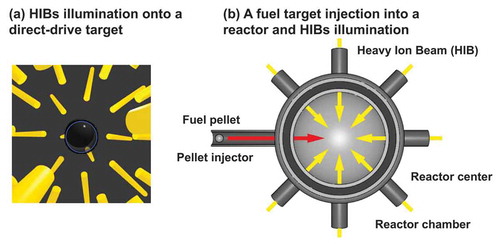
The final HIB pulse length should be about a few tens of ns. An advantage of heavy ions is the low space charge effect during the HIB acceleration, manipulation and transport. In the present HIF reactor designs, the candidates of the ion species include Pb+, CS+ and Au+. In this review, we focus on Pb+ ions. One of the merits of HIB accelerators is stable and repetitive operations with precise beam controllability. HIB accelerators have control capabilities of HIB focal position, pulse length, particle energy and axis manipulation. The HIB flexibility also relaxes the requirement of the HIBs illumination uniformity on the fuel target. This point is again discussed in Sections 3 and 5. Studies suggest that at least 32 HIBs are required to reduce the HIBs illumination non-uniformity on direct-drive fuel target [Citation46]. The HIBs illumination scheme is also important to release the fusion energy (see )), and is discussed in Section 3.
In ICF reactor, DT fuel target is repetitively injected and precisely aligned. When a spherical DT fuel is injected from outside a reactor, the DT fuel pellet is accelerated to a high speed of ~100 m/s to avoid the DT fuel melting by the reactor exhaust reactor gas [Citation36–41]. ) shows a schematic diagram for the fuel target injection into a reactor chamber. As shown in ), DT fuel is filled in fuel capsule. The DT fuel is cooled down to be a liquid, and the DT fuel layer is formed as shown in ) in the hollow fuel capsule. The stable fabrication of the fuel capsules is also important for the ICF reactor system [Citation59–63]. When the cryo-target in ) is employed, the most outer layer of Pb becomes a superconductor [Citation35–37] in a cryostat. The cryo-target is transferred to an injection gun, by which the cryo-target is injected into reactor. The traveling time of the fuel target injected is about 0.05 ~ 0.06 s [Citation36], which is estimated by the traveling distance (~5-6 m) divided by the target injection speed of ~100 m/s. During the time interval of about 0.05 ~ 0.06 s, it was found that the superconducting state of the cryo-target is not melted [Citation36]. The results in Refs. [Citation35–37] demonstrate that the target trajectory and speed are controlled by magnetic force. The HIF direct-drive target in ) is designed to have the heavy outer layer which becomes a superconducting state. This point would be also a merit of the HIF target. The outer superconducting shell would help reduce the target alignment error in reactor chamber in HIF [Citation35–37].
Between accelerator exit and fuel target aligned at a reactor chamber center, HIBs are transported. The distance would be ~5-10 m, depending on the reactor chamber radius (see )). Issues in HIF also include HIF reactor design, tritium breeding and handling, first wall configuration, control of exhaust reactor gas, activation of the reactor structure, etc. For example, accelerators should be protected from the reactor exhaust backward gas [Citation64]. DT fusion products are neutrons and alpha particles. Therefore, the fusion products would be relatively easy to handle. However, the reactor structure, which would be made of Al, is activated by 14.1 MeV neutrons. The management of activated structures should be considered to keep our environment clean.
HIB final transport near and inside the reactor chamber has been also intensively studied [Citation65–67]. It was considered that charged HIB is transported in a vacuum to fuel target, because heavy ions are not seriously influenced by their net charge. Almost ballistically heavy ions can be transported between accelerator exit to fuel target in reactor center. In order to enhance the HIB controllability, charge neutralization of HIB has been studied well. Experimentally at LBNL and theoretically at Princeton University and Japan, HIB space charge neutralization, focusing and manipulation are studied [Citation65–72]. Plasma electrons are supplied to neutralize the HIB charge from a gas plasma preformed in space or at the material surface by active or passive discharges [Citation65–72]. HIB instabilities were studied inside reactor gas, and the results show that HIB is rather stable during the transport in reactor gas against the two-stream and filamentation instabilities [Citation67,Citation73,Citation74].
3. Heavy ion interaction with material
Heavy ion interaction is explained rather well by the Coulomb collisions with target material electrons and ions [Citation28,Citation30]. The stopping power of a target is the sum of those of target nuclei
, target bound electrons
, free electrons
and target ions
[Citation28–30,Citation75,Citation76]. One can find each term in Refs. [Citation11,Citation28,Citation30]. The stopping power comes mostly from the Coulomb collisions. When a projectile ion speed is slow, the stopping power becomes large from the nature of the Coulomb collision. When fusion target material is heated by HIBs illumination, usually the energy absorber layer in ) is heated to ~200-300 eV, and the pressure peak appears there. When material temperature becomes high, material-free electrons contribute to the stopping power. At the same time, plasma electron waves are also excited and the free-electron stopping power is slightly enhanced compared with that by the bound electrons. The stopping power enhancement induces the ion stopping range shortening [Citation29,Citation77,Citation78]. The ionization degree of swift heavy ions changes as they move though materials. The ionization degree would be called the effective charge [Citation28,Citation30]. In the review, numerical studies include all the effects on the stopping power. The energy deposition peak, that is, the Bragg peak (see ), appears near the stop point, which is designed to be localized in the energy deposition layer of the fuel target in ). All HIB ions deposit their energy inside the target material, and the target structure in ) becomes appropriate for HIF direct-drive fuel target. In Review, we focus on direct-drive fuel target. Energy deposition profile is predictable and well defined. In addition, the typical density gradient scale length
would be about several hundreds of μm around the pressure gradient peak, where the Rayleigh–Taylor instability appears during the fuel implosion. presents a schematic diagram of density and pressure profiles of imploding spherical fuel target near the pressure peak. The solid curve shows the density profile, and the dotted line the pressure profile. In HIF target implosion, the HIB stopping range is relatively large and ~500–700μm, depending on ion particle energy and target materials. The pressure gradient scale length is long as well, and the density gradient scale length L is also large ~several hundred micrometers or so. When the density gradient scale length
is large, the growth rate
reduction would be expected [Citation79,Citation80]:
. Here
is the implosion acceleration, and
the wave number. Therefore, short wavelength modes may be stabilized or mitigated in HIF, and the mode with
would be dangerous in HIF. The large density scale length of
is also one of the characteristic features of HIB interaction with matters.
Figure 5. Schematic diagram of density and pressure profiles of imploding spherical fuel target. The solid curve shows the density profile, and the dotted line the pressure profile. In HIF target implosion, HIB stopping range is relatively large and ~ 500–700μm, depending on the ion particle energy. The pressure gradient scale length is long as well, and the density gradient scale length L is also large ~several hundreds of μm or so
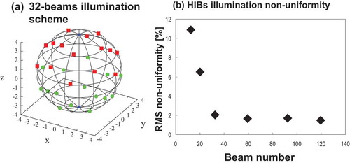
HIBs deposit the energy volumetrically. The Pb+ heavy ion energy would be ~8-10 GeV in HIF, and the stopping range is roughly ~0.5–0.7 mm or so, depending on target design. HIBs interaction with material should be considered in three dimensions [Citation46,Citation81–83]. HIBs illumination scheme is also important to obtain a low non-uniformity of HIBs driver energy deposition [Citation11,Citation46,Citation84–86]. shows (a) a typical example of 32 HIBs illumination scheme onto a spherical fuel target [Citation11,Citation44,Citation46] and (b) the HIBs illumination RMS non-uniformity versus the HIBs number employed. ) presents that the minimal HIBs number would be 32 to obtain a low driver beam illumination non-uniformity of a few percent [Citation33,Citation34]. In , we employ Pb+ ion HIBs with the mean particle energy of 8 GeV. The beam radius at the entrance of reactor chamber wall Ren is 35 mm, and the reactor chamber radius is assumed to be 5 m. The beam particle density distribution is the Gaussian one. The longitudinal temperature of HIB ions is 100 MeV. The beam transverse emittance εr is 3.5 mm mrad [Citation84]. The target temperature increases linearly during HIB deposition from 0.025 eV to 300 eV in this case in ). We employ a Pb + Al pellet structure with 4 mm external radius in ). The Pb mass density is 11.3 g/cm3. In the pellet structure, the outer Pb layer thickness is 0.06 mm. The results on the HIBs illumination non-uniformity are found in Ref [Citation84]., including the mode analyses.
In addition to single heavy ions as HIF driver, it would be valuable to mention cluster ion beam for ICF. We presently see a reevaluation of the cluster ion beam (CIB) approach to ICF, including cluster ion acceleration, cluster fragmentation and target correlated stopping of cluster ions [Citation87–90]. The CIB drive HIF demonstrates a potential for ICF through the enhanced and correlated ion stopping together with a lower q/A [Citation87,Citation88], which may relax the accelerator design further, compared with that for the conventional HIB accelerators. At the same time, the cluster ion source and the stable cluster acceleration should be further studied experimentally [Citation90].
Figure 6. (a) A typical 32 HIBs illumination scheme onto a direct-drive fuel target, and (b) the RMS HIBs illumination non-uniformity versus the total HIBs number. The result shows that at least 32 HIBs are needed to obtain a low illumination non-uniformity
4. High energy density physics with heavy ion beam
Besides HIF studies, research on high-energy density physics (HEDP) [Citation91,Citation92] has been explored based on HIB to investigate high temperature, high density and high pressure, which normally cannot be attained in nature on earth [Citation12,Citation24,Citation93–99]. In HIB-based HEDP, the target state of matter is in a temperature of about ~1 eV, a pressure of ~GPa or more and about solid density. HEDP contributes widely from fundamental physics to applications to understand plasmas, materials at extreme states, space, nuclear physics and engineering, radiation matter interaction, etc. HEDP research topics include non-ideal equation of state (EOS), strongly coupled plasma, non-ideal electrical and heat conduction [Citation100,Citation101], phase transitions at extreme states [Citation96–99], radiation-rich plasmas and other fundamental phenomena in plasmas. HEDP is also closely relating to ICF.
Here we introduce interesting HEDP studies based on HIB. Reference [Citation102] shows an interesting study plan to investigate a dense and warm matter. A target material is compressed by a diamond anvil cell, and the compressed material is illuminated by an HIB. HIB deposits its energy uniformly in a relatively large volume in high density.
Other HEDP studies are conducted and planned at the existing and constructing HIB facilities of FAIR [Citation19], HIAF [Citation20–22,Citation48–50], NDCX II [Citation18,Citation47] and an induction accelerator at High Energy Accelerator Research Organization (KEK), Tsukuba, Japan [Citation103]. At FAIR, GSI, Darmstadt, EOS and HEDP studies are planned at various material states with phase transition, driven by HIB [Citation97,Citation98,Citation104–115]. A magnetized plasma compression [Citation24] is also planned at FAIR, and an annular HIB illuminates a cylindrical hollow target. One of the research purposes of the magnetized plasma is to focus the HIB [Citation24], as a part of the HEDgeHOB Collaboration at FAIR [Citation104]. HEDP studies are being performed under the experiments LAPLAS (Laboratory Planetary Sciences) and HIHEX (Heavy Ion Heating and Expansion) at HEDgeHOB at FAIR with collaborators including scientists in Darmstadt, Germany, Univ. de Castilla-La Mancha, Spain and others [Citation98,Citation105–115]. An annular HIB is created by a HIB wobbler, in which the HIB axis is oscillated at a frequency of ~1 GHz to create the axial and azimuthal symmetry of the HED state in the cylindrical target [Citation24–26,Citation107,Citation115]. HIAF is planned to be operated in 2024 in China. Studies at HIAF include EOS, material phase transitions, hydrodynamic behavior of matter, ion interaction with materials in the HED state [Citation22]. At KEK, Japan, HEDP and ICF based on a cluster ion beam (CIB) are being considered [Citation12,Citation87–90,Citation103,Citation116]. For example, Si clusters are efficiently formed in an ellipsoidal-shaped cell with a Si crystal at the focal point of the cell. The Si crystal is illuminated by an intense laser, Si clusters are formed and confined in the cell by a shock wave created in the cell [Citation116]. The KEK induction accelerator accelerates giant Si clusters successfully [Citation12,Citation103,Citation117]. In Refs. [Citation87–89,Citation118,Citation119], cluster ion-based ICF is studied, though further studies are needed, including size distribution control of cluster ions, stable cluster ion acceleration and transport, cluster ion beam interaction with matter, etc. Relating to cluster ion interaction with solid material, correlation effect among ions of one cluster would introduce an enhancement of ion stopping power [Citation87–89]. On the other hand, a peculiar ion-overtaking behavior between two Si ions of one Si cluster was also found in a Si-cluster solid interaction theoretically [Citation90]. Near future experiments are needed to confirm the stopping power enhancement and physics in cluster ion interaction with material.
5. Energy release in heavy ion inertial fusion
In this section, we present fusion fuel target implosion and fusion energy release in HIF. A typical HIBs input pulse shape is shown in ). The foot pulse in ) kicks the DT fuel by a weak initial shock wave, and the main pulse with the higher intensity accelerates the DT fuel by the pressure gradient explained in . The input HIBs energy is converted to the DT fuel kinetic energy first. DT fuel is accelerated to ~m/s. An example time history of the DT fuel implosion speed is presented in ). In this example case, the fuel outer radius is 4 mm, the Pb layer thickness is 30μm, the energy absorber is the 460μm thick Al, and the DT fuel of 2.68 mg is confined in the fuel target capsule in ). The DT inner surface is at 3.43 mm, and the initial densities of Pb and Al are the solid density. The initial target temperature was set to be 0.1 eV. When the 32 HIBs irradiate the fuel target with the illumination scheme in ) [Citation44,Citation84], the simulation result in ) was obtained [Citation31]. A two-dimensional (2D) fluid implosion code was used to analyze the implosion dynamics [Citation81–83,Citation120]. The precise HIBs energy deposition profile was also computed together with the target plasma behavior [Citation31,Citation120].
Figure 7. (a) A typical input pulse of HIBs, and (b) the history of an example DT fuel implosion speed. SOURCE: Ref [Citation31]., doi.org/10.1038/s41598-019-43,221-7
![Figure 7. (a) A typical input pulse of HIBs, and (b) the history of an example DT fuel implosion speed. SOURCE: Ref [Citation31]., doi.org/10.1038/s41598-019-43,221-7](/cms/asset/b078652f-8b2e-41ac-afe5-a0e01c20de12/tapx_a_1873860_f0007_b.gif)
shows the ion temperature distributions at (a) t = 20.0 ns, (b) 29.0 ns, (c) 29.8 ns, (d) 30.8 ns, (e) 31.5 ns, and (f) 31.8 ns. In this case , and the fusion energy output gain is 62.4, which is a good number of the fusion energy gain
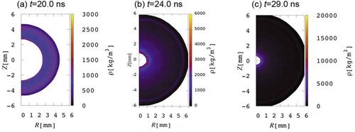
in HIF. The HIBs illumination non-uniformity was ~2% in . During the DT fuel implosion and stagnation, the initial small implosion non-uniformity grows as shown in ) during the implosion. Even with the evident non-uniformity, the DT fuel is successfully ignited and burnt. shows the mass density distributions for this example case. In ) the implosion non-uniformity also appears in the density distributions.
Figure 8. Ion temperature distributions at (a) t = 20.0ns, (b) 29.0ns, (c) 29.8ns, (d) 30.8ns, (e) 31.5ns and (f) 31.8ns. In this case, the 32 HIBs illuminates the HIF target in ) with the HIBs illumination scheme in ). The multiple HIBs introduce a small illumination non-uniformity (see Figure 8(a)). The initial HIBs illumination non-uniformity is about 2% in this example case, and the fusion energy gain is 62.4
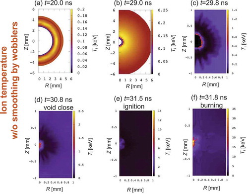
Figure 9. Mass density distributions at (a) t = 20.0ns, (b) 24.0ns and (c) 29.0ns
Here we revisit and estimate requirement for implosion non-uniformity. at the stagnation decides the fusion energy output. When a small implosion non-uniformity appears,
decreases from the perfect uniform
. The total DT mass is fixed during the implosion, and
is proportional to
. Therefore,
. On the other hand, nonuniformity
of implosion acceleration
would be estimated by
, where
is the fuel initial radius and
the density compression ratio of the DT fuel. The density compression ratio
may be about 1000 in HIF. We obtain the relation of
. In ICF reactor power plant, the degradation threshold of
would be about 0.5 ~ 0.8, and
should be less than about 3 ~ 4% [Citation33,Citation34]. shows the relation between
and
. The results above and in reproduce the results obtained in Refs. [Citation33,Citation34]. When the density compression ratio becomes higher, the non-uniformity requirement becomes stringent.
Figure 10. Relation between implosion non-uniformity and degradation of
As presented in Sections 1 and 2, HIB accelerators have flexibility to control the HIB axis position. HIB accelerators can oscillate the HIB axis with a high frequency ~100 MHz-1 GHz [Citation24–26]. The axis-oscillating or wobbling HIB also provides a unique tool to smooth the HIBs illumination non-uniformity in the HIF target implosion [Citation31,Citation42,Citation43,Citation46]. The wobbling HIBs are applied to smooth HIBs illumination non-uniformity in fuel target implosion.
The idea of the non-uniformity smoothing by the wobblers comes from feedforward control theory [Citation31,Citation121–125]. shows the initial perturbation growth in an unstable plasma system. At , the perturbation grows, and in at the same time another perturbation, which has the inverse phase, is added to compensate the perturbation growth. The perturbation is mitigated even in plasma systems. In HIF target implosion, multiple HIBs illuminate fuel target, and HIBs introduce a small non-uniformity. If HIBs axes are oscillated or wobbled in time, the HIBs illumination non-uniformity would be mitigated.
Figure 11. Perturbation mitigation mechanism. In an unstable plasma, a perturbation grows in time. At , if another perturbation with the inverse phase is applied to the system, the overall perturbation superimposed is mitigated, similar to the feedforward control
If a single mode is introduced in a plasma, the amplitude
of the perturbation becomes
. For stable system
is negative, and for unstable system
shows the instability growth rate. Here
is the wave length. An ideal dynamic smoothing mechanism is shown in [Citation122–125]. In heavy ion accelerators HIB axis can be oscillated or wobbled in a controlled manner to realize the dynamic smoothing of HIB illumination non-uniformity [Citation24–26].
A superimposed perturbation may be expressed for a physical quantity at
as follows:
Here we assume a uniform oscillation in time for the perturbed driver. In EquationEquation (1)(1)
(1) the amplitude is described by
,
shows the wobbling frequency of the driving beam, and
is the phase shift of the perturbations superimposed. The integrated perturbation at
is derived as follows:
When , the system is stable and EquationEquation (2)
(2)
(2) shows a simple dynamic smoothing of the perturbations. When
, the amplitude reduction ratio becomes
[Citation122–124]. Even for
we can still expect the significant mitigation. At this point, it should be noted that the integrated perturbation amplitude is mitigated well, but the growth rate
of the instability does not change. The result in EquationEquation (2)
(2)
(2) suggests that the wobbling frequency Ω should be high or comparable compared with the instability growth rate of
for the effective mitigation of the perturbation amplitude. The dynamic smoothing or mitigation mechanism is rather simple and easy to apply to instability mitigations in plasmas and fluids [Citation43,Citation122–125]. Especially the Rayleigh–Taylor (R-T) instability tends to appear during the DT fuel implosion in ICF. When the dynamic mitigation mechanism is applied to the R-T instability, it was found that the R-T instability growth is mitigated well [Citation31,Citation122,Citation123].
The dynamic smoothing mechanism was applied to the HIF target implosion to smooth the HIBs illumination non-uniformity by the spirally axis-oscillating HIBs [Citation31,Citation42]. shows a schematic diagram of the HIB rotation or wobbling behavior. In Refs. [Citation31,Citation42], 32 HIBs axes oscillate spirally from the initial axis positions shown in ). After around one rotation, each HIB rotates along the circle trajectory. The HIBs with the simple circularly oscillation induce a large initial imprint of the illumination uniformity [Citation42]. The spirally oscillating or wobbling HIBs smooth the HIBs illumination non-uniformity well [Citation42]. It is expected that the HIBs wobbling motion realizes the dynamic smoothing and mitigation mechanism in HIF target implosion.
Figure 12. Schematic diagram for a spirally rotating HIB, illuminating on a spherical fuel target. Initially the HIB center stays at the optimal position to reduce the initial imprint of the illumination non-uniformity. After around one rotation, each HIB axis tends to a circle rotation. The HIB wobbling behavior contributes to smooth the illumination non-uniformity, and mitigates the implosion non-uniformity. The dynamic mitigation mechanism would be realized by the HIBs wobbling motion
Including the wobbling motion of the 32 HIBs [Citation120], another 2D implosion simulation was performed [Citation31], and shows the ion temperature distribution at =29 ns. Compared with the result in ) without the HIBs wobbling, it is apparent that the spatial non-uniformity is smoothed by the wobbling HIBs. For both the cases in b) the difference is just the HIBs wobbling motion in the computation conditions. In this case, the HIBs wobbling frequency is 424 MHz. shows the mode analyses of the DT fuel ion temperature at
=25 ns for the cases (a) with and (b) without the wobbling HIBs. The mode analyses are performed based on the Legendre function
, and the mode
shows the mode of the Legendre function [Citation126] in .
Figure 13. Ion temperature distributions near the target center at 29ns for the cases (a) with the HIBs wobbling motion and (b) without the wobbling. SOURCE: Ref [Citation31]., doi.org/10.1038/s41598-019-43,221-7
![Figure 13. Ion temperature distributions near the target center at 29ns for the cases (a) with the HIBs wobbling motion and (b) without the wobbling. SOURCE: Ref [Citation31]., doi.org/10.1038/s41598-019-43,221-7](/cms/asset/3c56b14b-1757-4ace-ac3f-9db326a9419e/tapx_a_1873860_f0013_oc.jpg)
Figure 14. Mode analyses of the DT fuel ion temperature distributions near the target center at 25ns (a) with the HIBs wobbling motion and (b) without the wobbling. When the wobbling HIBs are employed, the implosion non-uniformity is successfully mitigated. SOURCE: Ref [Citation31]., doi.org/10.1038/s41598-019-43,221-7
![Figure 14. Mode analyses of the DT fuel ion temperature distributions near the target center at 25ns (a) with the HIBs wobbling motion and (b) without the wobbling. When the wobbling HIBs are employed, the implosion non-uniformity is successfully mitigated. SOURCE: Ref [Citation31]., doi.org/10.1038/s41598-019-43,221-7](/cms/asset/062034e2-bb1d-4951-b0ae-fc9d2307b078/tapx_a_1873860_f0014_b.gif)
Relating to EquationEquation (2)(2)
(2) and on the dynamic mitigation and smoothing mechanism, we also checked the phase of the implosion acceleration non-uniformity. The implosion acceleration distributions are presented in . During the HIBs half rotation between 6 turns and 6.5 turns of the rotating HIBs, the phase of the implosion acceleration non-uniformity of the DT fuel is clearly inversed. The result means that the phase of the implosion acceleration non-uniformity is controlled externally by the driver HIBs wobbling behavior. From EquationEquation (2)
(2)
(2) and the relating theory of the dynamic control mechanism, the HIBs illumination non-uniformity is smoothed, and the R-T instability would be also mitigated. The fusion output gain
becomes 81 for this case with the wobbling frequency of 424 MHz, though without the wobbling behavior
was 62.4. The detail parameter studies are also presented in Ref [Citation31,Citation127]., including a relation between
and
of the wobbling frequency.
Figure 15. Implosion acceleration distributions of DT fuel along the azimuthal direction with the HIBs wobbling behavior. The implosion acceleration non-uniformity is clearly controlled by the wobbling motion. During the half rotation of the wobbling HIBs, the phase of the implosion acceleration non-uniformity is inversed. The results demonstrate that the dynamic mitigation mechanism works well to smooth the HIB illumination non-uniformity and to mitigate the implosion non-uniformity. SOURCE: Ref [Citation31]., doi.org/10.1038/s41598-019-43,221-7
![Figure 15. Implosion acceleration distributions of DT fuel along the azimuthal direction with the HIBs wobbling behavior. The implosion acceleration non-uniformity is clearly controlled by the wobbling motion. During the half rotation of the wobbling HIBs, the phase of the implosion acceleration non-uniformity is inversed. The results demonstrate that the dynamic mitigation mechanism works well to smooth the HIB illumination non-uniformity and to mitigate the implosion non-uniformity. SOURCE: Ref [Citation31]., doi.org/10.1038/s41598-019-43,221-7](/cms/asset/e0fc85d4-96a6-4d8f-94b7-6a03450ea266/tapx_a_1873860_f0015_b.gif)
Relating to how to produce the wobbling HIBs [Citation24,Citation25], precision studies are required to investigate the effect of the wobbling error on the implosion uniformity in the future.
Here other topics relating to fuel target physics are briefly summarized. DT fuel target alignment error in a fusion reactor is also one of the issues in ICF. As shown in ), ICF target is injected into reactor chamber, and the research results show that the target alignment error should be less than 100 ~ 120μm in HIF [Citation11,Citation31,Citation46]. The target injection control technique into a reactor has been also studied well to reduce the target alignment error [Citation35–37], as shown in Section 2. In Refs. [Citation35–37] the control method was proposed theoretically to reduce the target alignment error in ICF. In the near future we need experimental verifications on the target alignment. In this review, we assume each fuel target contains the same amount of D and T [Citation11,Citation128]. In addition to DT reactions, DD reactions also contribute to the T creation in DT fuel target [Citation1–3,Citation52]. The results in Ref [Citation128] show that 20 ~ 30% reduction of tritium amount in DT pellet still produces a sufficient fusion energy output in DT ICF reactor. In other words, T amount can be reduced significantly without a notable reduction in DT fusion energy output. In this review, we focus on direct-drive fuel target scheme in HIF. HIBs deposit their energy in a target energy absorber volumetrically. For the 8 GeV Pb+ ion, the stopping range is ~500-700μm in metal target materials. If heavy ion particle energy can be reduced significantly or correlation effect on cluster ion stopping power is enhanced [Citation87–90,Citation129], HIB ion stopping range would be shortened. In this case, it may be expected to increase the target material temperature and the radiation temperature, and the radiation energy would dominate the energy transfer in the target energy absorbing layer and in the implosion phase. Indirect drive fuel targets have been also studied in HIF [Citation130,Citation131]. The radiation effect on the implosion dynamics was also studied even in a direct-drive HIF target [Citation132], in which a low-density foam was inserted in the HIBs energy absorber to enhance the radiation energy conversion from HIBs energy inside the target material. The inserted foam creates a wider density valley, in which radiation is confined and radiation transport in the target lateral direction contributes to smooth HIBs illumination non-uniformity additionally [Citation132].
6. Summary and perspectives
The present status of HIF research activities is introduced and discussed concisely in review. HIB accelerators may open a road to our future fusion energy release. The most remarkable merit in HIF is the high energy efficiency of HIB accelerator, which relaxes the ICF requirements to release fusion energy. The requirement for fusion energy gain is relaxed to be ~50-70. The high controllability of HIB accelerators is another merit. The HIF fuel target structure, which has a relatively thick energy absorber and creates a long density gradient, contribute to the relatively uniform target implosion. In Review all the merits and demerits in HIF are presented and discussed, as well as the recent scientific results and the recent international projects relating to HIB.
DT fusion targets at fusion reactor center would be imploded, ignited and burnt with the repetition rate of 10 ~ 15 Hz, and would supply ~GW electricity to society in the future. Many researchers and scientists have contributed to HIF studies toward our future fusion energy source. Currently, it seems that fatal flaws have not been found in the HIF fusion scenario, though experimental research is required further.
At present new accelerators are being built in the world: HIAF near Hong Kong in China and FAIR at Darmstadt, Germany, as well as the KEK induction accelerator. The activities planned in accelerator projects are oriented to basic physics and HEDP, as well as fundamental studies toward HIF. We need to continue the HIF related studies toward our future stable energy source.
Acknowledgments
The work was partly supported by JSPS (Japan Society for the Promotion of Science), MEXT (Ministry of Education, Culture, Sports, Science and Technology, Japan), CORE (Center for Optical Research and Education, Utsunomiya University), and ILE/Osaka University. The authors also would like to extend their acknowledgements to friends and colleagues in HIF research group in Japan, Tokyo Inst. of Tech., Nagaoka Univ. of Tech., KEK, Varna Technical University, Bulgaria, HIF-VNL, U.S.A., Inst. Modern Phys, CAS (Chinese Academy of Sciences), Xi’an Jiao Tong Univ., Shanghai Jiao Tong Univ., Fudan Univ., China, GSI, Germany, ITEP, Russia, Univ. de Castilla-La Mancha, Spain and Utsunomiya Univ. Our former and present colleagues and graduate students have contributed partly to the HIF studies, and they are also acknowledged. Finally, the authors also would like to acknowledge the reviewers and editor(s) of Advances in Physics: X. Their valuable comments and suggestions certainly make our paper rich and highly readable.
Disclosure statement
No potential conflict of interest was reported by the authors.
References
- Kikuchi M. Frontiers in fusion research: physics and fusion. London, UK: Springer; 2011.
- Niu K. Nuclear Fusion. Cambridge, UK: Cambridge Univ. Press; 2009.
- Atzeni S, Meyer-ter-Vehn J. The physics of inertial fusion: beam plasma interaction, hydrodynamics, hot dense matter. Int Ser Monogr Phys. 2009. Oxford Univ. Press, U. S. A..
- Available from: https://www.iter.org/. Accessed on June 30, 2020
- Aymar R, Barabaschi P, Shimomura Y. The ITER design. Plasma Phys Control Fusion. 2002;44:519.
- Mirnov SV. Tokamak evolution and view to future. Nucl Fusion. 2019;59:015001.
- Ongena J, Koch R, Wolf R, et al. Magnetic-confinement fusion. Nat Phys. 2016;12:398.
- Nuckolls J, Wood L, Thiessen A, et al. Laser compression of matter to super-high densities: thermonuclear (CTR) applications. Nature. 1972;239:139.
- Lindl JD. Inertial confinement fusion. New York: Springer; 1998.
- Betti R, Hurricane O. Inertial-confinement fusion with lasers. Nat Phys. 2016;12:435.
- Kawata S, Karino T, Ogoyski AI. Review of heavy-ion inertial fusion physics. Matter Radiat Extremes. 2016;1:89.
- Horioka K. Progress in particle-beam-driven inertial fusion research: activities in Japan. Matter Radiat Extremes. 2018;3:12.
- Böhne D, Hofmann I, Kessler G, et al. HIBALL—a conceptual design study of a heavy-ion driven inertial confinement fusion power plant. Nucl Eng Des. 1982;73:195.
- Hofmann I, Plass G. Technol GSI Rep GSI. 1998;98-06.
- Niu K, Kawata S. Proposal of power plant by light ion beam fusion. Fusion Technol. 1987;11:365.
- Hofmann I. Review of accelerator driven heavy ion nuclear fusion. Matter Radiat Extremes. 2018;3:1.
- Sharkov B, Varentsov D. Experiments on extreme states of matter towards HIF at FAIR. Nucl Instrum Methods A. 2014;733:238.
- Seidl PA, Barnard JJ, Davidson RC, et al. Short-pulse, compressed ion beams at the neutralized drift compression experiment. J Phys Conf Ser. 2016;717:012079.
- Available from: http://www.fair-center.eu/public/what-is-fair.html,FAIRproject. Accessed on June 30, 2020.
- Yang JC, Xia JW, Xiao GQ, et al. High Intensity heavy ion accelerator facility (HIAF) in China. Nucl Instr Meth B. 2013;317:263.
- Available from: http://hiaf.impcas.ac.cn/hiaf_en/public/c/news.html,HIAFproject Accessed on June 30, 2020.
- Ma X, Wen WQ, Zhang SF, et al. HIAF: new opportunities for atomic physics with highly charged heavy ions. Nucl Instr Meth B. 2017;408:169.
- Takayama K, Briggs R. Induction accelerators. Berlin Heidelberg: Springer; 2011.
- Sharkov BY, Hoffmann DHH, Golubev AA, et al. High energy density physics with intense ion beams. Matter Radiat Extremes. 2016;1:28.
- Qin H, Davidson RC, Logan BG. Centroid and envelope dynamics of high-intensity charged-particle beams in an external focusing lattice and oscillating wobbler. Phys Rev Lett. 2010;104:254801.
- Arnold RC, Colton E, Fenster S, et al. Utilization of high energy, small emittance accelerators for ICF target experiments. Nucl Instrum Methods. 1982;199:557.
- Jackson JD. Classical Electrodynamics. 3rd ed. New York: Wiley; 1998.
- Ziegler JF, Biersack JP, Littmark U. The stopping and range of ions in matter. Vol. 1. New York: Pergamon; 1985.
- Ichimaru S. Statistical plasma physics, volume I: basic principles. Boca Raton: CRC Press; 2019.
- Mehlhorn TA. A finite material temperature model for ion energy deposition in ion-driven inertial confinement fusion targets. J Appl Phys. 1981;52:6522.
- Sato R, Kawata S, Karino T, et al. Non-uniformity smoothing of direct-driven fuel target implosion by phase control in heavy ion inertial fusion. Sci Rep. 2019;9:6659.
- Daiber JW, Hertzberg A, Wittliff CE. Laser-generated implosions. Phys Fluids. 1966;9:617.
- Emery MH, Orens JH, Gardner JH, et al. Influence of nonuniform laser intensities on ablatively accelerated targets. Phys Rev Lett. 1982;48:253.
- Kawata S, Niu K. Effect of nonuniform implosion of target on fusion parameters. J Phys Soc Jpn. 1984;53:3416.
- Tsuji R. Trajectory adjusting system using a magnetic lens for a Pb-coated superconducting IFE target. Fusion Eng Des. 2006;81:2877.
- Kubo T, Karino T, Kato H, et al. Fuel pellet alignment in heavy-ion inertial fusion reactor. IEEE Trans Plasma Sci. 2019;47:2.
- Nakamura H, Kubo T, Karino T, et al. Fuel pellet injection into heavy-ion inertial fusion reactor. High Energy Density Phys. 2020;35:100741.
- Goodin DT, Gibson CR, Petzoldt RW, et al. Developing the basis for target injection and tracking in inertial fusion energy power plants. Fusion Eng Des. 2002;60:27.
- Petzoldt RW, Cherry M, Alexander NB, et al. Design of an inertial fusion energy Target tracking and position prediction system. Fusion Technol. 2001;39:678.
- Petzoldt RW, Goodin DT, Nikroo A, et al. Direct drive target survival during injection in an inertial fusion energy power plant. Nucl Fusion. 2002;42:1351.
- Petzoldt RW. IFE target injection and tracking experiment. Fusion Technol. 1998;34:831.
- Kawata S, Kurosaki T, Noguchi K, et al. Wobblers and Rayleigh–Taylor instability mitigation in HIF target implosion. Nucl Instrum Methods A. 2014;733:211.
- Kawata S, Noguchi K, Suzuki T, et al. Nonuniformity mitigation of beam illumination in heavy ion inertial fusion. Phys Scr. 2014;89:088001.
- Skupsky S, Lee K. Uniformity of energy deposition for laser driven fusion. J Appl Phys. 1983;54:3662.
- Murakami M. Irradiation system based on dodecahedron for inertial confinement fusion. Appl Phys Lett. 1995;66:1587.
- Miyazawa S, Ogoyski AI, Kawata S, et al. Robust heavy-ion-beam illumination against a direct-drive-pellet displacement in inertial confinement fusion. Phys Plasmas. 2005;12:122702.
- Barnard JJ, More RM, Terry M, et al. NDCX-II target experiments and simulations. Nucl Instrum Methods A. 2014;733:45.
- Available from: http://hiaf.impcas.ac.cn/hiaf_en/public/,HIAFhomepage. Accessed on June 30, 2020.
- Ren J, Zhao Y, Chen R, et al. Hydrodynamic response of solid target heated by heavy ion beams from future facility HIAF. Nucl Instr Meth B. 2017;406:703.
- Cheng R, Lei Y, Zhou X, et al. Warm dense matter research at HIAF. Matter Radiat Extremes. 2018;3:85.
- Kawata S, Okamura M, Horioka K, et al. arXiv:2005.07520. 2020.
- Richardson AS, 2019 NRL PLASMA FORMULARY. 2019. Available from: https://www.nrl.navy.mil/ppd/sites/www.nrl.navy.mil.ppd/files/pdfs/NRL_Formulary_2019.pdf. Accessed on June 30, 2020.
- Hurricane OA, Callahan DA, Casey DT, et al. Fuel gain exceeding unity in an inertially confined fusion implosion. Nature. 2014;506:343.
- Park H-S, Hurricane OA, Callahan DA, et al. High-adiabat high-foot inertial confinement fusion implosion experiments on the national ignition facility. Phys Rev Lett. 2014;112:055001.
- Okamura M. Laser ion source for heavy ion inertial fusion. Matter Radiat Extremes. 2018;3:61.
- N.J. Peacock and R.S. Pease Sources of highly stripped ions. J. Phys. D: Appl. Phys. 1969; 2:1705.
- Byckovsky YA, Eliseev VF, Kozyrev YP, et al. Sov Patent. Laser generator of multi-charged ions for accelerators. 1969;324:938.
- Karino T, Okamura M, Kanesue T, et al. Plasma instability inside solenoid with laser ion source. Rev Sci Instrum. 2020;91:053303.
- Available from: https://www.ga.com/inertial-fusion/fabrication, GA (General Atomics) homepage. Accessed on June 30, 2020.
- Spindloe C, Fukuda Y, Fitzsimmons P, et al. Review of HPLSE special issue on target fabrication. High Power Laser Sci Eng. 2018;6:e13. and references therein.
- Du K, Liu M, Wang T, et al. Recent progress in ICF target fabrication at RCLF. Matter Radiat Extremes. 2018;3:135.
- Yamaki T, ed., Inst. Plasma Phys. Nagoya Univ.; 1985. (Report IPPJ-663).
- Dudziak DJ, Herrmannsfeldt WB. 1986. (SLAC-PUB-4034).
- Kondo S, Karino T, Iinuma T, et al. Researches on a reactor core in heavy ion inertial fusion. Laser Part Beams. 2016;34:705.
- Roy PK, Yu SS, Henestroza E, et al. Drift Compression of an Intense Neutralized Ion Beam. Phys Rev Lett. 2005;95:234801.
- Berdanier W, Roy PK, Kaganovich IR. Intense ion beam neutralization using underdense background plasma. Phys Plasmas. 2015;22:013104.
- Kawata S, Sonobe R, Someya T, et al. Final beam transport in HIF. Nucl Instrum Methods A. 2005;544:98.
- Someya T, Kawata S, Nakamura T, et al. Beam final transport and direct-drive pellet implosion in heavy-ion fusion. Fusion Sci Technol. 2017;43:282.
- Chen BZ, Wu D, Ren JR, et al. Transport of intense particle beams in large-scale plasmas. Phys Rev E. 2020;101:051203(R).
- Stepanov AD, Gilson EP, Grisham LR, et al. Dynamics of ion beam charge neutralization by ferroelectric plasma sources. Phys Plasmas. 2016;23:043113.
- Lan C, Kaganovich ID. Neutralization of ion beam by electron injection: excitation and propagation of electrostatic solitary waves. Phys Plasmas. 2020;27:043104.
- Lan C, Kaganovich ID. Neutralization of ion beam by electron injection: accumulation of cold electrons. Phys Plasmas. 2020;27:043108.
- Okada T, Niu K. Filamentation and two-stream instabilities of light ion beams in fusion target chambers. J Phys Soc Jpn. 1981;50:3845.
- Hubbard RF, Tidman DA. Filamentation instability of ion beams focused in pellet-fusion reactors. Phys Rev Lett. 1978;41:866.
- Peter T, Meyer-ter-Vehn J. Energy loss of heavy ions in dense plasma. I. Linear and nonlinear Vlasov theory for the stopping power. Phys Rev A. 1991;43:1998.
- Peter T, Meyer-ter-Vehn J. Energy loss of heavy ions in dense plasma. II. Nonequilibrium charge states and stopping powers. Phys Rev A. 1991;43:2015.
- Slutz SA, Mehlhorn TA. Ion beam range shortening and the possibility of thermal instability. Appl Phys Lett. 1981;39:885.
- Kawata S. arXiv:1504.01831. 2015.
- Bodner SE. Rayleigh-Taylor instability and laser-pellet fusion. Phys Rev Lett. 1974;33:761.
- Takabe H, Mima K. Self-consistent growth rate of the Rayleigh–Taylor instability in an ablatively accelerating plasma. Phys Fluids. 1985;28:3676.
- Ogoyski AI, Someya T, Kawata S. Code OK1—Simulation of multi-beam irradiation on a spherical target in heavy ion fusion. Comput Phys Commun. 2004;157:160.
- Ogoyski AI, Kawata S, Someya T. Code OK2—A simulation code of ion-beam illumination on an arbitrary shape and structure target. Comput Phys Commun. 2004;161:143.
- Ogoyski AI, Kawata S, Popov PH. Code OK3 – an upgraded version of OK2 with beam wobbling function. Comput Phys Commun. 2010;181:1332.
- Someya T, Ogoyski AI, Kawata S, et al. Heavy-ion beam illumination on a direct-driven pellet in heavy-ion inertial fusion. Phys Rev ST Accel Beams. 2004;7:044701.
- Temporal M, Canaud B, Laffite S, et al. Illumination uniformity of a capsule directly driven by a laser facility with 32 or 48 directions of irradiation. Phys Plasmas. 2010;17:064504.
- Murakami M. Design of a conic irradiation system for laser fusion. Fusion Eng Design. 1999;44:111.
- Deutsch C, Bret A, Eliezer S, et al. Inertial Fusion Driven by Intense Cluster Ion Beams. Fusion Technol. 1997;31:1.
- Tahir NA, Lutz KJ, Geb O, et al. Inertial confinement fusion using hohlraum radiation generated by heavy-ion clusters. Phys. Plasmas 4 (1997) p.796.
- Wang GQ, Ma PET, Wang YN, et al. Multidimensional measures of response and fluctuations in stochastic dynamical systems. Phys Rev A. 2012;86:043201.
- Kawata S, Deutsch C, Gu YJ. Peculiar behavior of Si cluster ions in a high-energy-density solid Al plasma. Phys Rev E. 2019;99:011201(R).
- National Research Council. Frontiers in high energy density physics: the X-games of contemporary science. Washington, DC: The National Academies Press; 2003.
- National Academies of Sciences, Engineering, and Medicine. Plasma science: enabling technology, sustainability, security, and exploration. Washington, DC: The National Academies Press; 2020.
- Wu D, Yu W, Zhao YT, et al. Particle-in-cell simulation of transport and energy deposition of intense proton beams in solid-state materials. Phys Rev E. 2019;100:013208.
- Zhang L, Zhao Y, Ren J, et al. Warm-dense-matter state of iron generated by intense heavy-ion beams. IEEE Trans Plasma Sci. 2018;47:853.
- Zhang L, Zhao YT, Ren JR, et al. Phys Plasmas. 2018;25:113108.
- Schoenberg K, Bagnoud V, Blazevic A, et al. High-energy-density-science capabilities at the facility for antiproton and ion research. Phys Plasmas. 2020;27:043103.
- Tahir NA, Neumayer P, Lomonosov IV, et al. High-energy-density-science capabilities at the facility for antiproton and ion research. Phys Plasmas. 2020;27:043103.
- Tahir NA, Deutsch C, Fortov VE, et al. Proposal for the study of thermophysical properties of high-energy-density matter using current and future heavy-ion accelerator facilities at GSI Darmstadt. Phys Rev Lett. 2005;95:035001.
- Tahir NA, Kain V, Schmidt R, et al. The CERN large hadron collider as a tool to study high-energy density matter. Phys Rev Lett. 2005;94:135004.
- Kim KY, Yellampalle B, Glownia JH, et al. Measurements of terahertz electrical conductivity of intense laser-heated dense aluminum plasmas. Phys Rev Lett. 2008;100:135002.
- Yoneda H, Morikami H, Ueda K, et al. Ultrashort-pulse laser ellipsometric pump-probe experiments on gold targets. Phys Rev Lett. 2003;91:075004.
- Sasaki T, Kikuchi T, Harada N, et al. Target design for high energy density physics experiment using intense ion beams. J Phys Conf Ser. 2010;244:042019.
- Takayama K, Arakida Y, Dixit T, et al. Experimental demonstration of the induction synchrotron. Phys Rev Lett. 2007;98:054801.
- Tahir NA, Spiller P, Shutov A, et al. Proposed High Energy Density Physics Research Using Intense Particle Beams at FAIR: The HEDgeHOB Collaboration. IEEE Trans Plasma Sci. 2009;37:1267.
- Tahir NA, Spiller P, Udrea S, et al. Studies of equation of state properties of high-energy density matter using intense heavy ion beams at the future FAIR facility: The HEDgeHOB collaboration. Nucl Instr Meth Phys Res B. 2006;245:85.
- Tahir NA, Deutsch C, Fortov VE, et al. Studies of strongly coupled plasmas using intense heavy ion beams at the future FAIR facility: the HEDgeHOB collaboration. Contrib Plasma Phys. 2005;45:229.
- Tahir NA, Deutsch C, Fortov VE, et al. Generation of a hollow ion beam: calculation of the rotation frequency required to accommodate symmetry constraint. Phys Rev E. 2003;67:017501.
- Tahir NA, Udrea S, Deutsch C, et al. Target heating in high-energy-density matter experiments at the proposed GSI FAIR facility: Non-linear bunch rotation in SIS100 and optimization of spot size and pulse length. Laser Part Beams. 2004;22:485–28.
- Piriz AR, Temporal M, López Cela JJ, et al. Target design for the cylindrical compression of matter driven by heavy ion beams. Nucl Instrum Methods Phys Res A. 2005;544:27.
- Tahir NA, Deutsch C, Fortov VE, et al. Intense heavy ion beams as a tool to induce high-energy-density states in matter. Contrib Plasma Phys. 2003;43:373.
- Tahir NA, Adonin A, Deutsch C, et al. Studies of heavy ion-induced high-energy density states in matter at the GSI Darmstadt SIS-18 and future FAIR facility. Nucl Instrum Methods Phys Res A. 2005;544:16.
- Temporal M, Piriz AR, Grandjouan N, et al. Numerical analysis of a multilayered cylindrical target compression driven by a rotating intense heavy ion beam. Laser Part Beams. 2003;21:609.
- Temporal M, López Cela JJ, Piriz AR, et al. Compression of a cylindrical hydrogen sample driven by an intense co-axial heavy ion beam. Laser Part Beams. 2005;23:137.
- Piriz AR, Tahir NA, López Cela JJ, et al. Analytical models for the design of the LAPLAS experiment. Contrb Plasma Phys. 2007;47:213.
- Piriz AR, Temporal M, López Cela JJ, et al. Symmetry analysis of cylindrical implosions driven by high-frequency rotating ion beams. Plasma Phys Control Fusion. 2003;45:1733.
- Iwata Y, Tomita K, Uchida T, et al. Crystallographic coalescence of crystalline silicon clusters into superlattice structures. Cryst Growth Des. 2015;15:2119.
- Takayama K, Adachi T, Wake M, et al. Racetrack-shape fixed field induction accelerator for giant cluster ions. Phys Rev ST Accel Beams. 2015;18:050101.
- Deutsch C. Interaction of ion cluster beams with cold matter and dense plasmas. Laser Part Beams. 1990;8:541.
- Deutsch C. Correlated ion stopping in dense plasmas. Matter Radiat Extreme. 2019;4:034201.
- Sato R, Kawata S, Karino T, et al. Code O-SUKI: simulation of direct-drive fuel target implosion in heavy ion inertial fusion. Comput Phys Commun. 2019;240:83.
- Franklin GF, Powell J, Emami-Naeini A. Feedback control of dynamic systems. Global Edition ed. Pearson Education Ltd., Edinburgh Gate, Harlow, Esex CM20 2JE, England; 2014.
- Kawata S. Dynamic mitigation of instabilities. Phys Plasmas. 2012;19:024503.
- Kawata S, Karino T. Robust dynamic mitigation of instabilities. Phys Plasmas. 2015;22:042106.
- Kawata S, Gu YJ, Li XF, et al. Dynamic stabilization of filamentation instability. Phys Plasmas. 2017;25:011601.
- Kawata S, Sato S,T, Teramoto T, et al. Radiation effect on pellet implosion and Rayleigh-Taylor instability in light-ion beam inertial confinement fusion. Laser Part Beams. 1993;11:757.
- Oliver EW, Boisvert DW, Clark CW, ed. NIST handbook of mathematical functions. New York, NY: Cambridge University Press; 2010.
- Uchibori K, Sato R, Karino T, et al. Development of fuel target implosion simulation system in heavy ion inertial confinement fusion. High Energy Density Phys. 2020;34:100748.
- Kawata S, Nakashima H. Tritium content of a DT pellet in inertial confinement fusion. Laser Part Beams. 1992;10:479e484.
- Ren J, Deng Z, Qi W, et al. Observation of a high degree of stopping for laser-accelerated intense proton beams in dense ionized matter. Nat Commun. 2020;11:5157.
- Tabak M, Callahan-Miller D, Ho DD-M, et al. Design of a distributed radiator target for inertial fusion driven from two sides with heavy ion beams. Nucl Fusion. 1998;38:509.
- Callahan-Miller DA, Tabak M. Distributed radiator, heavy ion target driven by Gaussian beams in a multibeam illumination geometry. Nucl Fusion. 1999;39:883e892.
- Someya T, Miyazawa K, Kikuchi T, et al. Direct-indirect mixture implosion in heavy ion fusion. Laser Part Beams. 2006;24:359.