
 ?Mathematical formulae have been encoded as MathML and are displayed in this HTML version using MathJax in order to improve their display. Uncheck the box to turn MathJax off. This feature requires Javascript. Click on a formula to zoom.
ABSTRACT
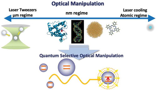
Realization of technologies for the mechanical manipulation (trapping, transportation, positioning, and aligning) of individual nanoscale particles has been an aspiration of researchers in various fields. Such technologies would enable us to manipulate nanomaterials, such as molecules, quantum dots, and nanocarbons, in a direct and selective way according to their individual quantum properties. Laser cooling and laser tweezers have been established as methods of remote manipulation of small objects for the atomic and micro-sized regimes, respectively. Despite the great successes of these technologies, the optical manipulation of nanoscale materials is still challenging because the thermal disturbance from the environment must be overcome by the very weak force on nanoscale objects. Technologies for selectively manipulating individual nanomaterial would enable the creation of structural order through optical sorting and isolation of targets according to their quantum individualities, and enable manipulation of chemical processes by selective control of molecular diffusion and condensation. In this article, we review recent studies on optical force on nanomaterials, mainly focusing on that arising from the linear and nonlinear optical responses due to electronic resonance of nanoparticles, and discuss the possibility of establishing nanoscale optical manipulation that could potentially contribute to the science and technology supporting our daily lives.
GRAPHICAL ABSTRACT
1. Introduction
The existence of optical force has been speculated from phenomena in the cosmos since Kepler’s discussion on comet tails in the early 17th century [Citation1]. Because the optical force is quite weak, it would have been a difficult phenomenon to detect on the ground in daily life at that time. In the late 19th century, Maxwell and Bartoli theoretically established the pressure of light based on electromagnetic theory [Citation2] and thermodynamics theory [Citation3], respectively. Subsequently, Lebedew [Citation4] and Nichols and Hull [Citation1] succeeded in measuring optical force by skillful methods and presenting precisive quantitative discussion. Subsequently, optical force changed from a subject of speculation inspired by cosmological phenomena to one of quantitative science on Earth, though application of the optical force had not yet been reported.
The invention of the laser has drastically changed the significance of optical force. Using the laser, Ashkin demonstrated the levitation of micrometer particles against gravity using the optical force [Citation5], which opened up the possibility of using optical force in technology. Thus, more than 250 years since the announcement by Kepler, and approximately 70 years since the measurements by Lebedew and Nichols and Hull, the optical force has become noticed as a significant technological tool. In Ref [Citation6,Citation7], Ashkin also discussed the idea that atomic motions can be controlled by the optical force if the laser has a frequency resonant with the transition energies between different electronic levels. Since then, from the 1970s to 1990s, technologies for motion control of atoms, such as the deceleration of atomic beams [Citation8], atomic gas cooling [Citation9], and trapping of atoms, have been significantly developed [Citation10], leading to current technologies that realize Bose–Einstein condensation [Citation11], quantum simulators [Citation12], and the optical lattice clock [Citation13]. On the other hand, the invention of laser tweezers to trap micro-sized particles by a single laser beam by Ashkin et al. [Citation14] opened another pathway for technologies to manipulate small objects such as cells, polymers, and biomolecules. This technology has especially promoted studies in the field of bioscience. For example, the trapping of viruses and living cells, and measurement of the mechanical force between biomolecules, were demonstrated [Citation15–17]. This technology has been used by several groups to observe the interaction of single myosin molecules with actin filaments [Citation18–20], revealing myosin–actin interaction by measuring the motion of laser-trapped micro-beads attached to those molecules. Thus, since Ashkin’s demonstrations, the optical force has become a significant laboratory tool for accumulating research knowledge.
With the development of fabrication technologies for various types of nanostructures and recent advances in observation techniques of phenomena in the nanoscale region, manipulation of nanometer-scale materials by optical forces has been attracting increasing interest. Organic molecules, quantum dots, nanocarbons, and nanodiamonds with fluorescent centers are typical examples of targets. If optical force technologies for mechanical manipulation (trapping, transportation, positioning, and aligning) of individual nano-objects could be realized, they could lead to unconventional types of nanofabrication technologies, highly sensitive sensing, controlling chemical processes, efficient nanometrology, etc. In other words, these optical force technologies could extend outside the laboratory and contribute to engineering that supports our daily lives. However, compared with the established technologies of laser tweezers for micrometer-sized particles and atom cooling for extremely small particles, the scheme of optical manipulation for nano-objects is still being developed and the realization of established technologies is currently challenging. The magnitude of optical force is usually proportional to the size of the targeted objects in the Rayleigh scattering regime. Hence, the force exerted on nano-objects is very weak compared with that on objects targeted by conventional laser tweezers. Further, typical targets interact with the solvent or gaseous environment where their thermal disturbance cannot be overcome by the trapping potential of the optical force. This situation is quite different from that of laser cooling.
Several types of approaches have been made during the last two decades. Due to the interaction between the electric field and polarization induced on nanomaterials, the nanomaterials feel the potential if the field intensity has a gradient. Thus, attractive or repulsive forces appear depending on the relative phase between the field and matter polarization. Tightly focused laser beams are useful for generating a strong gradient force, and researchers have successfully extended the staying time of molecules significantly in the focal spot [Citation21,Citation22]. Moreover, the concentration of molecules causes peculiar aggregation behavior [Citation23], which further enhances the optical force. A different version of this approach uses a steep gradient of strongly localized light electric field. Manipulation of nanomaterials such as thin films and nanoparticles by evanescent fields has been theoretically and experimentally demonstrated [Citation24,Citation25]. Further, it has been theoretically demonstrated that the strongly localized field around a sharpened metallic tip efficiently attracts nanomaterials [Citation26]. Since then, many methods of trapping by strongly localized fields associated with surface plasmon resonances (SPRs) have been proposed and demonstrated [Citation27–29], with various types of nanomaterials as the targets. Another approach is to use the resonance of the electronic transitions of nanomaterials . Generally, nanomaterials have quantized electronic levels with wavefunctions confined in the systems. If irradiated light frequency coincides with the transition energies, the optical response, and thus the exerted force, are resonantly enhanced. Although laser cooling uses the resonant absorption of photons, similar operation by applying precisive spectroscopy to nanomaterials is not as straightforward because the nanomaterials are comprised of many atoms, and hence, the absorption lines are usually complicated. However, typical nanomaterials have elementary excitations, such as excitons, coupled with certain reservoirs that make the absorption line rather wide. (An exciton is a bound state of an electron and a hole. Its ground state is usually the lowest excited state of insulator materials.) Such lines are good indicators of resonant excitation. In Refs. [Citation21,Citation22] this method is in fact targeted at resonant absorption lines of single molecules. Following theoretical studies of resonant optical manipulations [Citation30–32], several types of resonant optical manipulations have been demonstrated experimentally [Citation33–42].
An interesting aspect of using the resonance effect in optical manipulations is that it not only enhances the optical force but also realizes quantum-mechanically selective manipulation. Respective nanomaterials have quantum individualities because the wavefunctions and energy levels of confined electronic states and/or elementary excitations are dependent on the size, shape, and internal structures of the nanomaterials. Even when the constitutive atoms and crystalline structures are the same for different quantum dots, their different sizes or shapes cause different electronic level schemes. Thus, optical manipulation using the resonance effect has the potential to realize novel schemes to create structural order; for example, optical sorting and isolation of targets under different quantum resonance conditions. Also, the manipulation of crystal morphology and alignment, and manipulation of chemical processes by selective control of molecular diffusion and condensation would be realized. Further, the electronic resonance effect easily generates the nonlinear polarization that depends on the incident light intensity. This effect causes optical nonlinearity that greatly enhances the degrees of freedom to manipulate nanomaterials. In anticipation of such opportunities between macroscopic and atomic regimes (), this article reviews recent studies of optical manipulation of nanomaterials based on the electronic resonance effect.
Figure 1. Realization of an established scheme of optical manipulation of nanoscale materials is still challenging because the exerted force is considerably weaker than that arising in optical tweezers for micro-sized particles, and because the interaction with a complex environment must be overcome, unlike in atom cooling. However, there are various opportunities to assess the quantum-mechanical properties of individual nanomaterials through resonant optical manipulation because they exhibit individually discretized optical spectra due to quantum confinement of the electronic states
The remainder of this article is organized as follows. In Section 2, we provide formulations of optical force, and then, in Section 3, recent challenges in the optical manipulation of nanomaterials are discussed. In Section 4, we review studies of resonant optical manipulations, with theoretical proposals and experimental demonstrations introduced. Section 5 is devoted to discussions on optical manipulations using optical nonlinearity, introducing theoretical proposals of unconventional manipulations based on the nonlinear optical response of nanomaterials. An outlook and summary are given in Sections 6 and 7, respectively.
2. Optical force: from macroscopic objects to atoms
The optical force can be classified into two types: the dissipative force that arises when light momentum is transferred to objects through light scattering or absorption, and the gradient force that is generated when the electric field intensity is spatially inhomogeneous, under which the objects feel potential owing to the light-polarization interaction. The dissipative force is useful for pushing and transporting particles, whereas the gradient force is usually used for attracting and trapping particles.
The force exerted on a system comprising charged particles is expressed as the sum of the Lorentz force exerted on particles in an electromagnetic (EM) field as
where is the momentum of the center of mass of the particles,
,
,
, and
are the charge density, electric field, current density, and magnetic field at the position
, respectively. Because the time scale of the motion of objects is much longer than that of oscillation of the EM field, the above expression is usually time-averaged. In the actual calculation, if the size of the object is larger than the Rayleigh scattering regime, it is preferable to calculate the surface integral of the Maxwell stress tensor obtained by deforming the above expression [Citation43] rather than performing the volume integral. The time-averaged force for monochromatic light incidence is expressed as
where is the unit normal vector. The definition of
is
, where
and
are the vacuum permittivity and the vacuum permeability, respectively, and
is the unit tensor.
is the stress applied to the matter system surrounded by surface
.
denotes the time average. If the volume integral is preferred, we can recast EquationEquation (1)
(1)
(1) into [Citation44]
The electric field and polarization in the above expressions can be microscopic or macroscopic quantities. Even for objects much smaller than the light wavelength, we can calculate the exerted force using this formula if we can obtain the microscopic electric field and polarization according to their size, shape, and internal structures [Citation44].
By recasting the above general formulae of optical force, the expressions for simple cases can be obtained. For example, the following equation expresses the force exerted on a plain plate irradiated by plane-wave light that is incident normally:
where is the amplitude of the electric field of the incident light,
is the irradiated area, and
and
are the absorption and reflectance of the plate, respectively. In this case, no gradient of the electric field exists, and hence, only the dissipative force appears. The component proportional to
is the scattering force, and that proportional to
is the absorbing force. If the plate is irradiated with light of 1 mW power and
= 0,
= 1, all the light is absorbed and its momentum is transferred to a force of approximately 3.4 pN exerted on the plate. In contrast, in the case of spherical particles irradiated by plane-wave light propagating along the
-axis, the expression for the force can be rewritten as
where and
are the scattering and absorption cross sections, respectively,
is the anisotropy coefficient, and
is the force along the direction of light propagation. If isotropic scattering occurs, i.e.
, the ratio of the scattering and absorbing forces becomes equal to that of the scattering and absorption cross sections. If the scattering is totally backscattering, i.e.
, EquationEquation (5)
(5)
(5) becomes essentially the same as Equation (4).
In EquationEquations (4)(4)
(4) and (Equation5
(5)
(5) ), the optical properties of matter systems are expressed through the macroscopic quantities
and
, or
and
. On the other hand, if we approximate the particle by a single dipole, the Lorentz force can be expressed as
where is the dipole moment of the particle,
is the polarizability. The first term of EquationEquation (6)
(6)
(6) is the dipole force. This force appears in the presence of a gradient of field intensity. Thus, this force is the same as the gradient force and plays an important role in trapping particles in laser tweezers that use a tightly focused beam, and in the trapping of nanomaterials by a localized field, as discussed later. The second term is proportional to the time derivative of the Poynting vector that corresponds to the dissipative (scattering and absorbing) forces. This dipole picture is, of course, valid for particles much smaller than the light wavelength, i.e. in the Rayleigh scattering regime.
For smaller particles, i.e. atoms, an effective force arises when the light frequency is resonant with the electronic transition energy, i.e. resonant absorption is necessary. The optical force on atoms was formulated by Cohen-Tanoudji et al. [Citation45,Citation46], under the resonant condition with the atom and vacuum treated quantum-mechanically and the incident light treated classically. Assuming that the atomic moving distance during the excitation process is significantly shorter than the light wavelength, the exerted force on a two-level atom at rest in a vacuum is derived as
where is the angular frequency corresponding to the two-level transition energy,
and
are the angular frequency and wavevector of the incident light, respectively, and
is the Rabi frequency, which is proportional to the field amplitude
.
expresses the interaction strength between the light and the induced dipole.
is the radiative decay rate of the atom, and
is the population of the excited state under a stationary condition. The scattering force
in EquationEquation (8)
(8)
(8) is the time variation of the transferred momentum from photons to atoms and corresponds to the scattering force in EquationEquation (6)
(6)
(6) . The dipole force
in EquationEquation (9)
(9)
(9) is proportional to the gradient of the field intensity and corresponds to the gradient force in EquationEquation (6)
(6)
(6) . These equations show that both forces are resonantly enhanced when the light angular frequency approaches
. When the incident intensity is weak,
is proportional to
, whereas with an increase in incident intensity it becomes saturated and approaches
. In contrast,
is not saturated with the incident intensity.
Generally, nanomaterials have quantized electronic levels, and similar resonance effects occur in their optical responses. In nanomaterials such as organic molecules and quantum dots, excited states are types of elementary excitations such as excitons and coupling with the heat bath, i.e. phonons, exists; hence, the line widths of resonances are significantly wider than those of atoms. Usually, in optical tweezers, the laser frequency in the transparent region of the targeted matter is used to avoid damage to the samples. However, as discussed in the following sections, resonance effects play an important role in the optical manipulation of nanomaterials. Information on the resonant structures is contained in their polarizability or optical susceptibility. For example, in typical optical tweezers, the polarizability in EquationEquation (6)
(6)
(6) is considered constant in a transparent region. However, around the transition energies, this coefficient has resonant structures, similar to those seen in EquationEquations (8)
(8)
(8) and (Equation9
(9)
(9) ). The resonance effect can be expressed through the optical susceptibility
in the relation
, where
is the induced polarization that appears in EquationEquation (3)
(3)
(3) . In simple cases of linear response,
takes the form
where is defined by
, with the energies of the ground state and excited state denoted by
and
, respectively.
and
are the electron mass and electron density, respectively.
is the oscillator strength that expresses the strength of the relevant transition. The damping effect is neglected here for simplicity. Respective nanoparticles have individualities through the values of
and
. Further, if the incident intensity is strong,
is dependent on
, as seen in the energy denominators in EquationEquation (8)
(8)
(8) , and the optical nonlinearity should be considered in the resonant optical response as discussed in Section 5.
3. Challenges in optical manipulation of nanomaterials
Following the great success of laser tweezers in studies of biomolecular dynamics [Citation18–20], attempts have been made to trap various types of microparticles not only in bioscience, but also in a variety of other research fields such as organic photochemistry and micromachining. Further, recent efforts have been concentrated on developing the engineering of structured light to design the wavefront of the light beam and polarization vector, which leads to highly flexible laser-tweezing techniques. For example, Chen et al. theoretically proposed the pulling force by a Bessel beam, where multipole radiation induces forward scattering leading to pulling of particles [Citation47], and this proposal has been experimentally demonstrated [Citation48]. Recently, such non-intuitive optical forces arising from designed light fields have been drawing substantial interest because it would enhance the degrees of freedom to manipulate small particles. (For comprehensive reviews of the pulling force, see Refs. [Citation49,Citation50].)
As mentioned above, techniques using laser tweezers for manipulating microparticles have been highly developed, while recently, optical manipulation of nanomaterials has been attracting increasing interest. If direct approach to nanomaterials such as biomolecules, quantum dots, dye molecules, and nanocarbons is possible, more precise information of microscopic molecular dynamics can be obtained, and novel schemes for nanofabrication and highly sensitive sensing of molecules can be realized. Because of the weak force on nanomaterials and complicated interactions with the environment, it appears difficult to tightly trap them using a simple extension of conventional laser tweezers. However, if the diffusion or concentration of molecules in a small volume can be controlled, it would be useful to realize unconventional control, observation and measurement of molecular processes. The challenge of trapping nanomaterials started in the 1990s with targeting of metallic nanoparticles which have relatively high polarizability compared with non-metallic particles. Svoboda et al. demonstrated that metallic Rayleigh particles can be stably trapped where the gradient force is dominant in this size regime [Citation51] (see ). In addition, Sugiura et al. trapped metallic nanoparticles and demonstrated that trapped particles can be a scanning near-field optical microscope probe [Citation53]. Trapping of dye molecules and dye-doped nanopolymers has also been intensively conducted in the fields of biochemistry and organic photochemistry using a tightly focused laser beam. As mentioned before, Osborne et al. demonstrated the trapping of single dye molecules and reported that the staying time of molecules in the focal spot became significantly longer [Citation21]. Chirico et al. reported similar analysis for the control of diffusion of small fluorophores [Citation22]. Ito et al. demonstrated patterning and photochemical fixation of polymer nanoparticles by trapping particles with a tightly focused beam [Citation23] (see ). In addition, Hosokawa et al. succeeded in determining the concentration of nanopolymers with diameters of several tens of nanometers at the focal spot and discussed their dynamics in a trapping potential by observing fluorescence from dyes embedded in polymers [Citation54]. Further, they observed the cluster aggregation of particles, which induced deepening of trapping potential, using fluorescence correlation spectroscopy [Citation55].
Figure 2. (a) Schematic illustration of nanoparticle trapping by a tightly focused laser beam. (b) Trapped single gold sphere of 36 nm diameter with a 5 m scale bar (upper panel), and transmission electron micrograph of gold spheres with a 100 nm scale bar (lower panel). (Reprinted with permission from Ref [Citation51].
The Optical Society.) (c) Optical transmission (upper panel) and fluorescence (lower panel) images of patterned and fixed polymer nanoparticles created by scanning with trapping and excitation laser beams. (Reprinted with permission from Ref [Citation23].) (d) Schematic illustration of nanoparticle trapping by a strongly localized electric field causing a gradient force at the metallic nanogap. (e) Brownian motion of 200 nm polystyrene beads in conventional laser trapping (left panel) is strongly reduced by the assistance of nanogaps between gold nanoparticles (right panel). (Reprinted with permission from Ref [Citation27].) (f) Fixing micropatterns of DNA on a substrate with gold nanogaps. Fluorescence micrograph of the letter ‘A’ constructed from 14 microrings of assembled DNA. (Reprinted with permission from Ref [Citation52].©American Chemical Society)
![Figure 2. (a) Schematic illustration of nanoparticle trapping by a tightly focused laser beam. (b) Trapped single gold sphere of 36 nm diameter with a 5 μm scale bar (upper panel), and transmission electron micrograph of gold spheres with a 100 nm scale bar (lower panel). (Reprinted with permission from Ref [Citation51]. © The Optical Society.) (c) Optical transmission (upper panel) and fluorescence (lower panel) images of patterned and fixed polymer nanoparticles created by scanning with trapping and excitation laser beams. (Reprinted with permission from Ref [Citation23].) (d) Schematic illustration of nanoparticle trapping by a strongly localized electric field causing a gradient force at the metallic nanogap. (e) Brownian motion of 200 nm polystyrene beads in conventional laser trapping (left panel) is strongly reduced by the assistance of nanogaps between gold nanoparticles (right panel). (Reprinted with permission from Ref [Citation27].) (f) Fixing micropatterns of DNA on a substrate with gold nanogaps. Fluorescence micrograph of the letter ‘A’ constructed from 14 microrings of assembled DNA. (Reprinted with permission from Ref [Citation52].©American Chemical Society)](/cms/asset/328c0658-c918-4dbb-8c99-df4919c58d72/tapx_a_1885991_f0002_oc.jpg)
The steepness of the field gradient is limited if one uses the conventional focusing scheme of the laser beam. Therefore, different ideas have appeared to realize steeper field gradient. Novotny et al., theoretically proposed to use the strongly localized field around the sharpened metallic tip [Citation26]. The localized field with a steep field gradient appears around the tip and induces a sufficiently strong force to trap nano-objects. Okamoto et al. reported a numerical analysis of the optical force due to a localized field at the metallic nano-aperture that induces sufficiently strong force to trap subwavelength particles that overcome Brownian motion [Citation25]. These ideas have been developed into methods of trapping nanomaterials using optical antennas due to the localized SPR sustained at the nanogap between the metallic structures ()). For example, Grigorenko et al. experimentally demonstrated plasmon trapping of nanomaterials using a substrate with metallic nanostructure [Citation27]. They observed that 200 nm polystyrene beads were trapped at the nanogap and the Brownian motion of particles was significantly reduced ()). In addition, various demonstrations of trapping using localized SPR have been performed [Citation29,Citation56,Citation57]. This type of trapping does not require strong incident light to trap nanomaterials using a tightly focused beam, in contrast with typical laser tweezers, and the intensity is typically several kW/cm. However, even at this level of intensity, it is impossible to neglect the convection and thermophoresis induced by heat elevation due to plasmonic resonance, and it is not easy to analyze the particle motions distinguishing these effects from those of the optical force. Shoji et al. demonstrated an interesting ring formation in DNA particles trapped by localized SPR where the fine balance between the optical force, convection, and thermophoresis plays a crucial role ()) [Citation52]. On the other hand, recently, trapping by non-metallic substrates with nanostructures has been demonstrated as free of the problems caused by heat elevation [Citation58]. For the advanced achievements of optical force studies from microscale to nanoscale materials and their applications, see the recent review articles, such as Refs. [Citation59–62].
In the above examples, the majority of efforts have been directed at designing a light field for nanomaterials trapping. An alternative strategy is to use the intrinsic features of nanomaterials. Generally, nanomaterials have quantized electronic levels whose wavefunctions are coherently extended in larger volumes compared with electronic states in atoms, and transitions between these levels are associated with elementary excitations such as excitons. Because the line widths are wider than those of the atomic levels owing to the interaction with phonons or lattice vibrations, they are usually good indicators of resonant excitation. In the experiments of Osborne et al. and Chirico et al., the absorption lines of dye molecules were targeted in contrast with conventional laser tweezers [Citation21,Citation22]. Using the resonant condition leads to a significant improvement in trapping efficiency because the reaction cross section is resonantly enhanced near the electronic transition lines. Further, we note that using electronic transitions in the optical manipulation not only improves the trapping efficiency, but also enhances the degree of freedom to manipulate nanomaterials, because the exerted force becomes selective according to the individual quantum properties of the respective nanomaterials. In the next section, we review the recent progress of such resonant optical manipulations.
4. Optical manipulation of nanomaterials using electronically resonant optical response
If the frequency of the incident laser approaches the absorption line of the electronic transition of nanomaterials, the induced polarization is resonantly enhanced as understood from the energy denominator in EquationEquation (10)(10)
(10) (see ). The actual trapping efficiency near the absorption lines was examined and a positive effect has been reported, as mentioned in the above section [Citation21,Citation22]. The existence of favorable conditions for resonant trapping, though in a limited frequency region, has also been theoretically discussed [Citation31]. On the other hand, some theoretical demonstrations of optical manipulation using excitonic resonances in semiconductors have been made assuming cryogenic conditions [Citation30,Citation32,Citation63] ()). In Ref [Citation30], the optical force on nanofilms was evaluated for both propagating and evanescent waves, and a significant enhancement due to excitonic and cavity resonances was reported. Moreover, in Ref [Citation32,Citation63], it was proposed that the resonant enhancement of the optical response of quantized electronic states confined in nanoparticles not only causes enhancement of the optical force, but also realizes size-selective manipulations. Considering quantum dots (QDs), even if the constituent atoms and their crystalline structures are the same, the energies and wavefunctions of the electronic levels are different due to the different confinement conditions. Thus, respective QDs exhibit quantum-mechanical individuality in their optical properties, which is reflected in the appearance of an optical force. This means that selective manipulation according to the quantum-mechanical properties of nanomaterials is possible if a resonance effect is used [Citation44,Citation64].
Figure 3. (a) Schematic illustration of optical transitions between size-quantized electronic levels in nanomaterials. (b) Schematic illustration of the absorption spectrum of nanomaterials with peak structures of resonant absorption at quantized excitonic levels. (c) Schematic illustration of selective optical response for a specific light frequency by electronic resonance of a particular particle size. (d) Calculated spectra of acceleration exerted on CuCl nanoparticles with radii of 10, 11, and 12 nm irradiated by a traveling plane wave. The damping constant is assumed to be 0.2 meV. See Ref [Citation32] for calculation details
![Figure 3. (a) Schematic illustration of optical transitions between size-quantized electronic levels in nanomaterials. (b) Schematic illustration of the absorption spectrum of nanomaterials with peak structures of resonant absorption at quantized excitonic levels. (c) Schematic illustration of selective optical response for a specific light frequency by electronic resonance of a particular particle size. (d) Calculated spectra of acceleration exerted on CuCl nanoparticles with radii of 10, 11, and 12 nm irradiated by a traveling plane wave. The damping constant is assumed to be 0.2 meV. See Ref [Citation32] for calculation details](/cms/asset/b6f04aa0-c320-44c5-9ddf-741a594fa073/tapx_a_1885991_f0003_oc.jpg)
Overcoming some difficulties to perform selective manipulation in experiments, Inaba et al. reported the first demonstration of optical manipulation using excitonic resonance of QDs [Citation33](see ). They fabricated CuCl QDs in a liquid He environment in a cryostat using laser ablation. Using second-harmonic waves of a Ti:sapphire laser, they irradiated the CuCl QDs with UV light of a frequency resonant with Z excitons. After examinations using several frequencies, it was clarified that only the laser frequency resonant with the excitons could transport QDs over macroscopic distances. They also confirmed a significantly reduced size distribution of transported QDs compared with that immediately after ablation, although the size selectivity was not very fine because a pulsed laser was used to cover part of the range of the resonance line.
Figure 4. (a) Schematic of experimental setup. The sample holder with the CuCl target for ablation is set at the center of the cryostat. Inset: the manipulation laser passes through the pinhole on the sample holder. (b) SEM image of nanoparticles on a silicon substrate irradiated by the manipulation laser. Particles with diameters ranging from 10 nm to 50 nm are observed. (Reprinted with permission from Ref [Citation33].)
![Figure 4. (a) Schematic of experimental setup. The sample holder with the CuCl target for ablation is set at the center of the cryostat. Inset: the manipulation laser passes through the pinhole on the sample holder. (b) SEM image of nanoparticles on a silicon substrate irradiated by the manipulation laser. Particles with diameters ranging from 10 nm to 50 nm are observed. (Reprinted with permission from Ref [Citation33].)](/cms/asset/f0b19741-ffe1-4d83-b765-d1518a1144fa/tapx_a_1885991_f0004_oc.jpg)
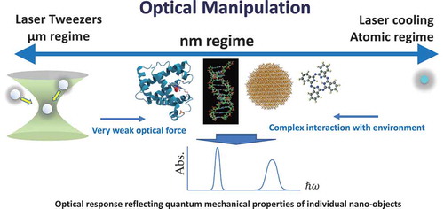
The significance of optical manipulation using the electronic resonance effect is that this scheme links microscopic dynamics in the manipulation targets to their center-of-mass macroscopic motions (see ). In studies of electronic schemes and their dynamics in molecules or QDs, their macroscopic motions are not usually explicitly considered. In addition, when we analyze the macroscopic motions of nanomaterials in certain environments, their electronic properties are not explicitly discussed in typical cases. Namely, these two types of degrees of freedom belong to different hierarchies of motion analysis. However, if we use an electronic resonance condition in optical manipulation, the energy level schemes and microscopic dynamics of nanomaterials are reflected in the manner of their movement. A typical application of resonant optical manipulation is sorting and selection of quantum-mechanical properties. Single-walled carbon nanotubes (SWCNTs) are good targets of such demonstrations because they exhibit sharp excitonic resonance lines that sensitively depend on their diameter and chirality. Using a tightly focused laser beam, Rodgers et al. demonstrated selective aggregation of particular species of SWCNTs [Citation36]. Subsequently, the possibility of selective transport of SWCNTs by traveling waves and trapping by standing waves has been theoretically discussed in detail by Ajiki et al. [Citation65], who calculated the optical force exerted on a SWCNT considering the excitonic effect under the effective-mass approximation. They found that the optical force becomes significantly large for typical laser intensities even at room temperature if the light frequency is close to the excitonic level (see ). Note that, although the diameter of an SWCNT is a couple of nanometers, sufficient force arises near resonance conditions because their length is usually macroscopic. The peak positions in optical force spectra are sensitive to the tube diameter and light polarization. Furthermore, the chirality dependence on excitons for similar diameter is relatively high. Therefore, it is possible to selectively sort and trap SWCNTs with a desired specific structure by tuning the applied field frequency. The same research group as in Ref [Citation36], recently demonstrated selective transport of SWCNTs at room temperature [Citation40]. They irradiated SWCNTs sustained in a microcapillary using an intense laser with a particular frequency injected from one end of the capillary, and verified that the targeted chirality of SWCNTs was successfully transported in a selective manner by observing the Raman signal at the other end of the capillary ().
Figure 5. Macroscopic motions of nanoparticles induced by light reflect their quantum-mechanical individualities via the resonant optical force. In this image, only the particles with resonance frequencies that coincide with the laser frequency are manipulated
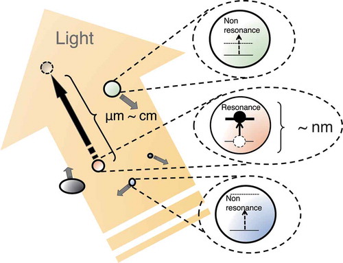
Figure 6. (a) Lattice structure of 2D graphite, which forms SWCNTs and the coordinate system. (b) Schematic illustration of an SWCNT and the coordinate system ,
, and
. (c) Schematic illustration of an applied EM field with polarization parallel to the tube axis. (d) Illustration of an applied EM field with perpendicular polarization. The direction of the wave vector
of the EM field is indicated by
perpendicular to the tube axis. (e) Calculated dissipative force for an EM field with parallel polarization. (f) Calculated dissipative force for an EM field with perpendicular polarization. (g) Calculated potential due to a gradient force for parallel polarization, shown as a function of SWCNT position
. The applied field energy is fixed at 0.88 eV, where an SWCNT with a diameter of 1.2 nm experiences red detuning. The inset shows the potential for perpendicular polarization. (h) Potential difference due to the gradient force for parallel polarization. The warping effect is included. The SWCNTs with chiral vectors (19,8), (18,6), and (17,4) are all metallic. See Ref [Citation65] for the detailed model and calculations. (Reprinted with permission from Ref [Citation65].©American Physical Society)
![Figure 6. (a) Lattice structure of 2D graphite, which forms SWCNTs and the coordinate system. (b) Schematic illustration of an SWCNT and the coordinate system x, y, and θ. (c) Schematic illustration of an applied EM field with polarization parallel to the tube axis. (d) Illustration of an applied EM field with perpendicular polarization. The direction of the wave vector q of the EM field is indicated by Z perpendicular to the tube axis. (e) Calculated dissipative force for an EM field with parallel polarization. (f) Calculated dissipative force for an EM field with perpendicular polarization. (g) Calculated potential due to a gradient force for parallel polarization, shown as a function of SWCNT position Z0. The applied field energy is fixed at 0.88 eV, where an SWCNT with a diameter of 1.2 nm experiences red detuning. The inset shows the potential for perpendicular polarization. (h) Potential difference due to the gradient force for parallel polarization. The warping effect is included. The SWCNTs with chiral vectors (19,8), (18,6), and (17,4) are all metallic. See Ref [Citation65] for the detailed model and calculations. (Reprinted with permission from Ref [Citation65].©American Physical Society)](/cms/asset/07b588ec-68f8-4848-bf4f-d9dcdcfec24c/tapx_a_1885991_f0006_oc.jpg)
Figure 7. (a) Experimental setup for selective optical transport of SWCNTs sustained in a microcapillary. The targeted chirality of the SWCNTs is transported in a selective way, and Raman spectroscopy is observed at the other end of the capillary. (b)–(e) Number of targeted SWCNTs with chirality (9,4) gradually increased. (Reprinted with permission from Ref [Citation40].©American Physical Society)
![Figure 7. (a) Experimental setup for selective optical transport of SWCNTs sustained in a microcapillary. The targeted chirality of the SWCNTs is transported in a selective way, and Raman spectroscopy is observed at the other end of the capillary. (b)–(e) Number of targeted SWCNTs with chirality (9,4) gradually increased. (Reprinted with permission from Ref [Citation40].©American Physical Society)](/cms/asset/e289b6c9-cfe1-430d-ae7f-eea6dd0c298a/tapx_a_1885991_f0007_oc.jpg)
As another target of resonant optical manipulation, the enantioselective transport of chiral molecules has been studied. Near the resonance lines of molecules, the selectivity of chirality is enhanced, which realizes different transportation distances between different enantiomers [Citation66].
The above examples show the selective transport in the case in which targeted quantum states are well isolated from other spectral structures ()). However, in actual situations, this is not always the case. For example: 1) If the resonant bodies are embedded in the mother matrix (e.g. a nanocrystal of diamond containing nitrogen-vacancy centers (NV centers) or a dye-doped polymer particle), the magnitude of the optical force applied to the whole particle is determined largely by the matrix size. Under this condition, selective manipulation based on the quantum properties of the embedded resonant bodies is difficult (see )). 2) If the spectral peak structures of the targeted QDs are masked by higher energy absorption of different groups of QDs with lower absorption edges, selective manipulation may be difficult (see )). These problems can be overcome if counter-propagating waves are used [Citation42,Citation67]. –h) show the scheme. There are two types of forces exerted on nanodiamonds containing NV centers (NVND), i.e. the scattering force on mother diamond crystals and the resonant absorbing force on NV centers. If the size of the nanodiamond is several tens of nanometers, the former is much stronger than the latter and, hence, distinguishing NVND from the pristine diamond (PD) using optical force is usually difficult. However, if we use counter-propagating waves, we can cancel non-resonant contributions, i.e. the scattering force and extract the contribution from the resonant part due to NV centers. Similarly, we can select targeted QDs even if problem 2) mentioned above exists (see ). A particularly noteworthy aspect of this scheme is the possibility to measure pure absorption spectra and their absolute values [Citation42,Citation67]. Single-nanoparticle spectroscopy is an exciting challenge in a variety of research fields. In most cases, the absorption coefficient is measured by various dissipative processes such as scattering, fluorescence or heating, which are not direct measurements of absorption. In contrast, the absorbing force directly reflects momentum transferred from light to matter. Thus, if we cancel the scattering force and measure the moving distance or evaluate the optical force including only the absorbing force, we can directly obtain the absorption coefficients or absorption spectra of single nanoparticles (see ). This form of spectroscopy, based on momentum change instead of energy change, can obtain absorption information independently of any dissipation processes. Selection and absorption spectroscopy based on counter-propagating light has been demonstrated experimentally using nanofibers, which limits the motion of nanoparticles to a one-dimensional space [Citation42] (see ). This scheme successfully performs selective manipulation of NVND and single-particle absorption spectroscopy. This scheme is an unconventional usage of optical force to realize ‘optical force spectroscopy’ [Citation42]. This experiment is a typical demonstration of linking optical force technologies to material science using resonant optical manipulation.
Figure 8. (a) Schematic of force spectra of nanoparticles with size-dependent resonance peaks. The incident light of a specific energy can selectively enhance interaction with the corresponding particles, and we can thus selectively transport them. (b) Schematic of force spectra of nanoparticles, with the resonant bodies embedded in the mother matrix. The optical force applied to a whole particle is determined largely by the matrix size. In this diagram, the exerted force is stronger for the particle with the spectrum represented in red, even if the photon energy is tuned to the peak of the spectrum represented in green. (c) Schematic of force spectra of the QDs of the two groups in regions of different sizes. In this case, selective manipulation of the QD group with a higher absorption edge (represented in green) is difficult because the force on the group with a lower absorption edge (represented in red) is stronger at the peak position of the former. (d) Schematic of optical manipulation with counter-propagating light waves. (e) Model of optical manipulation of nanodiamond particles with nitrogen-vacancy (NV) centers (NVND) by counter-propagating evanescent waves at the interface between glass and water. (f) Optical force spectra of NVND and pristine diamond (PD). The green and red lines represent the forces exerted on the NVND and PD, respectively. The dashed lines represent the forces with only light wave 1, and the solid lines represent the forces with counter-propagating light waves. (g) Trajectories of two particles for 5 s transport with only light wave 1. (h) Trajectories of two particles for 20 s transport with counter-propagating light waves. See Ref [Citation67] for details of the model and calculations. (Reprinted with permission from Ref [Citation67].)
![Figure 8. (a) Schematic of force spectra of nanoparticles with size-dependent resonance peaks. The incident light of a specific energy can selectively enhance interaction with the corresponding particles, and we can thus selectively transport them. (b) Schematic of force spectra of nanoparticles, with the resonant bodies embedded in the mother matrix. The optical force applied to a whole particle is determined largely by the matrix size. In this diagram, the exerted force is stronger for the particle with the spectrum represented in red, even if the photon energy is tuned to the peak of the spectrum represented in green. (c) Schematic of force spectra of the QDs of the two groups in regions of different sizes. In this case, selective manipulation of the QD group with a higher absorption edge (represented in green) is difficult because the force on the group with a lower absorption edge (represented in red) is stronger at the peak position of the former. (d) Schematic of optical manipulation with counter-propagating light waves. (e) Model of optical manipulation of nanodiamond particles with nitrogen-vacancy (NV) centers (NVND) by counter-propagating evanescent waves at the interface between glass and water. (f) Optical force spectra of NVND and pristine diamond (PD). The green and red lines represent the forces exerted on the NVND and PD, respectively. The dashed lines represent the forces with only light wave 1, and the solid lines represent the forces with counter-propagating light waves. (g) Trajectories of two particles for 5 s transport with only light wave 1. (h) Trajectories of two particles for 20 s transport with counter-propagating light waves. See Ref [Citation67] for details of the model and calculations. (Reprinted with permission from Ref [Citation67].)](/cms/asset/f1ec01fc-60dc-464f-a82a-3f372cdd7fd3/tapx_a_1885991_f0008_oc.jpg)
Figure 9. (a) Model of counter-propagating waves in liquid helium. An imaginary screen at = +7.5
m is assumed that catches and fixes the QDs. (b) Absorption spectra of the QDs. Red and green lines represent Groups 1 and 2, respectively. The total number of QDs for each group is 100 000, and the energy interval is 20
eV. (c) Absorption spectra of QDs that have reached the screen after 0.16 ms irradiation of light waves. The peak structures indicate that the targeted QDs within the highly limited range of transition energy are selectively transported. The other small numbers of QDs around the sharp peak are considered to have reached the screen stochastically by Brownian motion. The spectra of all QDs are represented by dotted lines for reference. (d) Schematic of the method to achieve a balance between the forces on the diamond as the mother matrix (scattering forces) using resonant and non-resonant light. Using two non-resonant light waves, it is possible to estimate the contribution of force arising solely from the diamond (outlined arrows) when the NVND is irradiated by a resonant light wave. Using counter-propagating light waves that realize a balance between the background forces, we can extract the pure contribution of the resonance (green filled arrows). (e) Photon energy spectrum of the transport distance of the NVND obtained by Brownian simulation and the fitting curve by the Lorentz function. The resonance center
= 2.320 eV and the dephasing constant of the NV center
= 19.35 meV are obtained as fitting parameters. The original values are assumed to be
= 2.320 eV and
= 20 meV. See Ref [Citation67] for details of the model and calculations. (Reprinted with permission from Ref [Citation67].)
![Figure 9. (a) Model of counter-propagating waves in liquid helium. An imaginary screen at z = +7.5 μm is assumed that catches and fixes the QDs. (b) Absorption spectra of the QDs. Red and green lines represent Groups 1 and 2, respectively. The total number of QDs for each group is 100 000, and the energy interval is 20 μeV. (c) Absorption spectra of QDs that have reached the screen after 0.16 ms irradiation of light waves. The peak structures indicate that the targeted QDs within the highly limited range of transition energy are selectively transported. The other small numbers of QDs around the sharp peak are considered to have reached the screen stochastically by Brownian motion. The spectra of all QDs are represented by dotted lines for reference. (d) Schematic of the method to achieve a balance between the forces on the diamond as the mother matrix (scattering forces) using resonant and non-resonant light. Using two non-resonant light waves, it is possible to estimate the contribution of force arising solely from the diamond (outlined arrows) when the NVND is irradiated by a resonant light wave. Using counter-propagating light waves that realize a balance between the background forces, we can extract the pure contribution of the resonance (green filled arrows). (e) Photon energy spectrum of the transport distance of the NVND obtained by Brownian simulation and the fitting curve by the Lorentz function. The resonance center ω0 = 2.320 eV and the dephasing constant of the NV center γ = 19.35 meV are obtained as fitting parameters. The original values are assumed to be ω0 = 2.320 eV and γ = 20 meV. See Ref [Citation67] for details of the model and calculations. (Reprinted with permission from Ref [Citation67].)](/cms/asset/cf99fc88-7ca8-4150-8ce2-419879730f6f/tapx_a_1885991_f0009_oc.jpg)
Figure 10. (a) Concept of selective optical manipulation and absorption spectroscopy of singe nanoparticles using counter-propagating light in a nanofiber. Nanodiamond particles are trapped by a gradient force arising from the evanescent field around the nanofiber, with their motion along the fiber controlled by the parameters of the two beams. (b) Experimental setup. (c) Selective transport of nanodiamond. As a result of the balance between the green and near-infrared lasers, the PDs (2 and 3) are pushed toward the left, and the NVNDs (1 and 4) are pushed toward the right. Only the scattering force acts on the PDs, whereas the absorption force additionally acts on the NVNDs to invert their direction of motion. (Reprinted with permission from Ref [Citation42].)
![Figure 10. (a) Concept of selective optical manipulation and absorption spectroscopy of singe nanoparticles using counter-propagating light in a nanofiber. Nanodiamond particles are trapped by a gradient force arising from the evanescent field around the nanofiber, with their motion along the fiber controlled by the parameters of the two beams. (b) Experimental setup. (c) Selective transport of nanodiamond. As a result of the balance between the green and near-infrared lasers, the PDs (2 and 3) are pushed toward the left, and the NVNDs (1 and 4) are pushed toward the right. Only the scattering force acts on the PDs, whereas the absorption force additionally acts on the NVNDs to invert their direction of motion. (Reprinted with permission from Ref [Citation42].)](/cms/asset/70e9acf5-54c9-4fc3-8709-33a5d4e80585/tapx_a_1885991_f0010_oc.jpg)
Here, we should mention that none of the above demonstrations of resonant optical manipulation include trapping by a single focused laser beam. They demonstrate optical transport by dissipative force and trapping by standing waves. It is known that, for a single beam, the dissipative force easily pushes the particles out of the focal spot under a resonance condition [Citation31,Citation68]. However, there have been many reports of enhanced trapping efficiency using a resonance effect in conventional single-beam trapping. As explained in Refs. [Citation21,Citation22], extension of the staying time has been achieved using the resonance absorption of molecules. In addition, some papers have reported effective trapping using resonant light [Citation34,Citation35,Citation38]. Although these results show interesting aspects of resonant optical trapping, it is difficult to explain these phenomena within a simple optical response theory as mentioned above. These puzzling aspects of resonant optical trapping had not been discussed explicitly before the 2010s. The approach to understanding these puzzling effects is discussed in the next section.
5. Optical manipulation of nanomaterials using nonlinearity in electronically resonant optical response
As explained in the previous section, Refs. [Citation21] and [Citation22] have successfully measured the optically biased diffusion of single organic molecules using a focused laser beam with a one-photon resonance frequency. Likewise, a significant increase in the trapping time of fluorophore-labeled antibodies when using resonant laser light has been reported [Citation34], wherein antibodies are trapped by a single focused beam. Recently, Shoji et al. demonstrated efficient trapping of myoglobin molecules containing a heme cofactor with a resonance absorption line [Citation38].
It is known that in the linear response regime, the condition of efficient trapping under a resonant condition is limited because, in a typical case, the dissipative force (scattering and absorbing forces), which pushes particles, is dominant and the frequency region favorable for trapping exists only in a very narrow spectral region below the resonance line. Further, note that above the resonance line, the phase relation between the light electric field and induced polarization becomes inverted from that below the resonance, which can be seen from the energy denominator of EquationEquation (10)(10)
(10) . This leads to an inversion of the force direction, which pushes the particle out of the focal spot even with a gradient force. However, the operated laser frequencies are reported to be above the maximum absorption energy of the single organic molecule in the experiments [Citation21,Citation34,Citation37]. Furthermore, the trapping force at energies above resonance is several times stronger than that below resonance for the same molecule [Citation22]. The demonstration conducted by Hosokawa et al. [Citation35] is more extreme; in their study, the trapping time was substantially increased by the addition of a resonant laser (at a wavelength of 532 nm), the intensity of which was several orders of magnitude weaker than that of the main non-resonant trapping laser (wavelength 1064 nm).
The key to understanding these puzzling effects is the nonlinear optical response of matter systems. The optical nonlinearity sometimes plays essential roles in the phenomena associated with optical force. For example, Ashkin et al. demonstrated a type of Kerr effect where the self-focusing of the incident beam was observed [Citation69]. In this experiment, they showed that Rayleigh particles suspended in a liquid were concentrated in a Gaussian beam by optical force. This effect causes a change of effective refractive index of the medium with light intensity, which results in the self-focusing of laser beams. Recently, Fardad et al. reported an effective positive Kerr effect by the suspension of metallic nanoparticles [Citation70]. Robust propagation of self-trapped light over long distances has been demonstrated using designed plasmonic nanoparticles for tunable polarizabilities. Also, Gautam et al. demonstrated a similar mechanism of self-guiding of light in human red blood cell suspensions [Citation71], which is useful for biological imaging. These examples demonstrated nonlinearity appearing through the dependence of the effective refractive index of a liquid solution on the light intensity, whereas the trapping of nanomaterials using nonlinear polarization of the targeted particles in themselves has been reported by Jiang et al., for the first time [Citation72]. They have revealed that the double potential minimum appears because of the optical nonlinear polarizability of metallic nanoparticles.
In typical conditions for efficient trapping of nanoparticles, the laser intensity is strong enough to cause nonlinearity. In particular, under the resonance conditions, the nonlinearity is easily caused by comparatively weak light. In the weak laser intensity regime, the induced polarization is proportional to the light electric field as shown in EquationEquation (10)(10)
(10) , which is within the linear response regime. However, generally, the optical susceptibility
of matter has a dependence on the electric field
, and if the field intensity is not very strong, the induced polarization
can be written in the form of perturbation expansion of the electric field
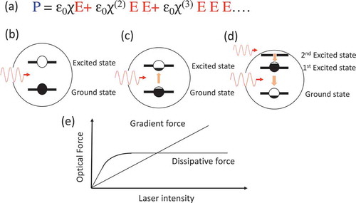
as described in ), whereas if the incident intensity is strong enough to result in significantly high occupancy probability of the excited state, we must consider the description beyond the perturbation regime ()). In many cases of trapping of nanomaterials, an optical response beyond the perturbation regime occurs because of the strength of the incident laser.
Figure 11. (a) Induced polarization expressed by perturbation expansion of electric field
in the weak excitation regime. (b) Schematic illustration of weak excitation regimes. The occupancy probability of the excited state is significantly less than unity. (c) With an increase in the excitation intensity, the occupancy probability of the excited state increases and approaches saturation. (d) In the presence of an upper level, the occupancy probability of the first excited state can be more than half, i.e. inverted probability is possible. (e) Schematic of dependences of the dissipative and gradient forces on the incident laser intensity. The dissipative force is saturated, whereas the gradient force is not
Here, we introduce our studies on optical trapping arising from the nonlinear optical response under the resonance conditions [Citation73,Citation74], for which we have theoretically analyzed the optical force in the nonlinear regime beyond the perturbation. We have formulated the induced polarization for three-level molecules (see )) based on the density matrix method [Citation75], for which the equations of the density matrix are solved under the conditions within two-photon processes. Using the induced polarization calculated in the above way, together with the background dielectric constant described according to the Clausius–Mossotti law including the radiation reaction effect [Citation76], we calculated optical force exerted on a single molecule irradiated with a tightly focused laser beam described by the angular spectrum representation [Citation77]. shows the optical force spectra exerted on the three-level molecule, the schematic energy scheme of which is depicted in ). From this figure, we can see that in the linear response regime, in the positive -region, the optical force is positive; i.e. a repulsive force around the absorption lines appears. If the damping constant is small, very narrow negative regions appear just below the absorption lines. Considering the thermal fluctuation of molecular resonance lines in media, formation of an efficient trapping potential seems difficult. However, in the case of strong excitation, this situation is totally changed. As in ), as the laser intensity increases, the Lorentzian line shape gradually changes to the dispersion type. Namely, the contribution of the gradient force to the total optical force becomes dominant in the nonlinear regime due to the saturation effect of the dissipative force, which is related to the strong broadening of the spectral line. This effect is explained as follows (see )). In the linear response regime, both the dissipative force and the gradient force are proportional to the incident intensity. However, in the nonlinear regime, the growth rate of the former decreases owing to optical saturation, and the former’s contribution subsequently becomes small. This means that the absorption becomes saturated, as does the dissipative force. In this situation, the nonlinear polarizability is notably increased with the opposite sign to the linear one, and they almost cancel each other out. This phenomenon has been discussed for the laser cooling technique [Citation46], as described by EquationEquation (9)
(9)
(9) . On the other hand, the gradient force increases even in this regime. Hence, the entire line shape changes to the dispersion type.
Figure 12. Nonlinear effect on nanoparticle trapping by a resonance laser. (a) Schematic of the model geometry of a particle irradiated with a focused laser beam. (b) Schematic of the energy level scheme of an assumed molecule (rhodamine) with vibration levels. and
are the transition energies between the second excited state and the ground state and between the first excited state and ground state, respectively, and
and
are the dipole moments corresponding to these transitions, respectively. (c) Photon energy dependence of the exerted force on a molecule along the
-direction for several values of the molecular dephasing constant. The vertical black solid lines show the transition energies of (b). Weak incident power (1 nW) is assumed, and hence, only the linear response occurs. The black curve shows a spectrum for only the background dielectric constant (non-resonant case). The attractive force arises across the entire spectral region indicated in this case. (d) Strong incident power (1 mW) is assumed, and a notable nonlinear effect appears. Above the resonance energy
, the direction of the force is inverted and it becomes attractive. The vertical gray lines show the photon energies employed in Ref [Citation21] (above
) and Ref [Citation22] (below
) to trap molecules. Reference [Citation22] reported a staying time of molecules in the focal spot four times longer for the former case than the latter, which is consistent with the present result. See Ref [Citation73,Citation74] for calculation details
![Figure 12. Nonlinear effect on nanoparticle trapping by a resonance laser. (a) Schematic of the model geometry of a particle irradiated with a focused laser beam. (b) Schematic of the energy level scheme of an assumed molecule (rhodamine) with vibration levels. ℏω31 and ℏω21 are the transition energies between the second excited state and the ground state and between the first excited state and ground state, respectively, and μ31 and μ21 are the dipole moments corresponding to these transitions, respectively. (c) Photon energy dependence of the exerted force on a molecule along the z-direction for several values of the molecular dephasing constant. The vertical black solid lines show the transition energies of (b). Weak incident power (1 nW) is assumed, and hence, only the linear response occurs. The black curve shows a spectrum for only the background dielectric constant (non-resonant case). The attractive force arises across the entire spectral region indicated in this case. (d) Strong incident power (1 mW) is assumed, and a notable nonlinear effect appears. Above the resonance energy ℏω21, the direction of the force is inverted and it becomes attractive. The vertical gray lines show the photon energies employed in Ref [Citation21] (above ℏω21) and Ref [Citation22] (below ℏω21) to trap molecules. Reference [Citation22] reported a staying time of molecules in the focal spot four times longer for the former case than the latter, which is consistent with the present result. See Ref [Citation73,Citation74] for calculation details](/cms/asset/e716e058-4dbe-4039-81ad-4eba0632a53d/tapx_a_1885991_f0012_oc.jpg)
If the particle is far from the focal spot in the negative -region, the contribution of the dissipative force is dominant because the gradient of the field is weak. Furthermore, the dissipative force is considerably stronger than that in the non-resonant condition. Therefore, it is expected that molecules with resonance energy near the incident photon energy could be strongly pushed forward to the focal spot, which might lead to an increase in molecular density near the focal spot compared with the non-resonant case. This is referred to as the resonance-drifting effect [Citation74]. shows the results of our Brownian dynamics simulation. As explained above, compared with the case of non-resonance, molecules in the resonant nonlinear case are strongly pushed from far in the negative
-region to the focal spot, and their speed is subsequently reduced owing to the saturation of the dissipative force. Finally, because of the inversion of the gradient force above the resonance energy, the molecules are trapped at the focal spot. If we consider only the linear response with the same laser intensity, the dissipation force strongly pushes the molecules away from the focal spot. Recently, this expected mechanism was experimentally confirmed by Kudo et al. [Citation41], who measured the particle immobilization time by optical trapping of dye-doped beads below and above the molecular resonance in the delicate setting of equal laser intensities. As a result, significant effective trapping above the resonance was achieved ().
Figure 13. (a) Schematic of the energy level scheme of an assumed molecular aggregate with vibration levels. (b) Schematic of model geometry of a particle irradiated with a focused laser beam. Particle (blue circle) is assumed to be a dye aggregate with 30 nm diameter. (c) Results of Brownian dynamics simulations. In the presence of the manipulation laser, compared with the case of diffusion alone (green line), the molecule gradually approaches the focal spot in the non-resonance case (blue line). In the case of resonance, the particle is pushed by a strong dissipative force, and passes through the focal spot if we consider only the linear response (pink line). If the nonlinear effect is considered, although the dissipative force is saturated to some extent even at the initial position, the molecule is strongly pushed forward to the focal spot owing to the resonance-drifting effect. Subsequently, the molecule is trapped around the focal spot because of the braking effect by the strong nonlinearity
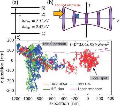
Figure 14. (a) Schematic of setup for optical trapping of individual particles. (b) Excitation (solid line) and emission (dashed line) spectra of dye-doped polystyrene particles in water solution. The vertical lines correspond to the wavelengths of the blue – (515 nm) and red – (532 nm) detuned lasers. Laser power dependence of the effective immobilization time with (c) red – and (d) blue-detuned lasers. (Reprinted with permission from Ref [Citation41]. The Optical Society.)
![Figure 14. (a) Schematic of setup for optical trapping of individual particles. (b) Excitation (solid line) and emission (dashed line) spectra of dye-doped polystyrene particles in water solution. The vertical lines correspond to the wavelengths of the blue – (515 nm) and red – (532 nm) detuned lasers. Laser power dependence of the effective immobilization time with (c) red – and (d) blue-detuned lasers. (Reprinted with permission from Ref [Citation41]. © The Optical Society.)](/cms/asset/bd9cdc05-35c0-4263-84d9-f0af0784d261/tapx_a_1885991_f0014_oc.jpg)
As explained above, we now understand that the hypothesis of nonlinear trapping has been realized. It is well known that, historically, the techniques of spectroscopy and manipulation of photons in optical devices have advanced rapidly since the consideration of nonlinear optical responses of matter systems because nonlinear processes address a considerably larger number of degrees of freedom than the linear process. Similarly, we can expect that the intentional implementation of nonlinear processes in optical manipulation will greatly enhance the degrees of freedom to manipulate nanomaterials. As mentioned above, optical manipulation considering the optical nonlinearity of targeted nanomaterials has been demonstrated for the first time using gold nanoparticles, for which a trapping potential with a double minimum was realized [Citation72]. While the effects in Ref [Citation72] were analyzed based on the perturbation scheme, many peculiar effects have been analyzed and proposed for the manipulation of nanomaterials excited strongly beyond perturbation [Citation73]. A two-color trapping scheme has been theoretically proposed for three-level molecules [Citation74,Citation78]. Unlike trapping using the frequency above the resonance line by single-beam irradiation [Citation73], if we use two-color beams for pumping tuned to the uppermost level and for trapping tuned to the second level, the trapping efficiency is drastically improved by more than an order of magnitude. This is because the excitation to generate gain becomes significantly more efficient owing to the tuning only to the uppermost level [Citation74] (see ). An interesting effect that occurs based on a similar mechanism is the ‘stimulated recoil force’ [Citation73,Citation74]. For three-level molecules, if we pump the molecules to generate gain in such a way that the pump beams do not generate a force, we can pull the particle as explained in . This theoretical prediction indicates that both the absorption and emission lines can be used for optical manipulation though only absorption lines have been used in the conventional optical trapping and transport. This type of inversion of the force direction by the nonlinear response can also be used to realize super-resolution trapping [Citation79] by using a scheme analogous to a stimulated emission depletion microscope [Citation80]. shows the concept of super-resolution trapping. If we have an array of hot spots sustaining localized SPRs as illustrated in ), many nanoparticles are trapped. However, because of the diffraction limit, it is impossible to limit the trapping area to the nanoscale using a typical Gaussian beam. However, if we irradiate a substrate with coaxial beams of Gaussian and Laguerre–Gaussian (LG) beams, the force direction on particles in the overlapping region is inverted, and particles are trapped only in a limited region around the singular point without an overlap because there is no pumping by the LG beam there. ) show the results of theoretical calculations to demonstrate optical trapping based on this concept. Note that this scheme does not necessarily require a substrate with metallic nanostructures, and only Gaussian and LG beams in a liquid solution or on the photonic crystals can realize similar super-resolution trapping. Recently, we have theoretically proposed that two-beam irradiation of nanoparticles on metallic nanostructures could also realize rotational direction switching of nanoparticles [Citation81] owing to a similar mechanism based on the nonlinear optical response.
Figure 15. (a) Single laser beam creating inverted occupancy probability of the first excited state, which inverts the direction of the gradient force above the first excited state and traps particles with the inverted force. (b) Pump beam creating an inverted occupancy probability of the first excited state through the excitation of the second excited state. The manipulation beam resonant with the first excited state traps particles. (c) Calculated results of optical force for cases (a) and (b). The force is enhanced by more than one order of magnitude. See Ref [Citation74,Citation78] for the model and calculation details
![Figure 15. (a) Single laser beam creating inverted occupancy probability of the first excited state, which inverts the direction of the gradient force above the first excited state and traps particles with the inverted force. (b) Pump beam creating an inverted occupancy probability of the first excited state through the excitation of the second excited state. The manipulation beam resonant with the first excited state traps particles. (c) Calculated results of optical force for cases (a) and (b). The force is enhanced by more than one order of magnitude. See Ref [Citation74,Citation78] for the model and calculation details](/cms/asset/f27df508-1986-4331-8267-540cf79577b0/tapx_a_1885991_f0015_oc.jpg)
Figure 16. Spectra of the radiation force along the direction of the traveling wave. The solid and broken lines represent the cases in which the target is irradiated and not irradiated, respectively, with the standing wave. See ref [Citation73] (also Focus in Physics 5, 95 (2012) of American Physical Society) for details
![Figure 16. Spectra of the radiation force along the direction of the traveling wave. The solid and broken lines represent the cases in which the target is irradiated and not irradiated, respectively, with the standing wave. See ref [Citation73] (also Focus in Physics 5, 95 (2012) of American Physical Society) for details](/cms/asset/de90485f-d4a3-4a68-b98e-c75de0467277/tapx_a_1885991_f0016_oc.jpg)
Figure 17. (a) Schematic illustration of the inversion of force direction on nanoparticles with particular resonance energies at metallic nanogaps. When nanoparticles are irradiated with a pump beam, a particular group of particles have gain, and the force on them is inverted. (b) Schematic illustration of super-resolution trapping. With only a Gaussian (G) beam (black circle), nanoparticles are trapped at every hot spot (nanogap). If they are irradiated with a Laguerre–Gaussian (LG) beam (donut beam), nanoparticles are also released from the hot spots in the overlapping region of these two beams because of force inversion. Thus, nanoparticles are trapped only around the singular point of the LG beam. (c)–(h) Calculated map of optical force on nanoparticles. Blue (red) color refers to the force toward (away from) the gap center. (c) Both Gaussian and LG beams are delivered. (e, f) Enlarged maps of areas 1 and 2 in (c). Black arrows show the direction map of the exerted force. (d) Only the Gaussian beam is delivered. (g, h) Enlarged maps of areas 3 and 4 in (d). The meaning of the black arrows is the same as in (e) and (f). (Parts (c)–(h) reprinted with permission from Ref [Citation79].©American Chemical Society)
![Figure 17. (a) Schematic illustration of the inversion of force direction on nanoparticles with particular resonance energies at metallic nanogaps. When nanoparticles are irradiated with a pump beam, a particular group of particles have gain, and the force on them is inverted. (b) Schematic illustration of super-resolution trapping. With only a Gaussian (G) beam (black circle), nanoparticles are trapped at every hot spot (nanogap). If they are irradiated with a Laguerre–Gaussian (LG) beam (donut beam), nanoparticles are also released from the hot spots in the overlapping region of these two beams because of force inversion. Thus, nanoparticles are trapped only around the singular point of the LG beam. (c)–(h) Calculated map of optical force on nanoparticles. Blue (red) color refers to the force toward (away from) the gap center. (c) Both Gaussian and LG beams are delivered. (e, f) Enlarged maps of areas 1 and 2 in (c). Black arrows show the direction map of the exerted force. (d) Only the Gaussian beam is delivered. (g, h) Enlarged maps of areas 3 and 4 in (d). The meaning of the black arrows is the same as in (e) and (f). (Parts (c)–(h) reprinted with permission from Ref [Citation79].©American Chemical Society)](/cms/asset/a81c05d6-f214-4fbf-9ece-8287520663ce/tapx_a_1885991_f0017_oc.jpg)
As an experimental demonstration, Setoura et al. recently reported optical manipulations based on the pump-controlled absorption line using photochromic reactions [Citation82], which is a typical form of optical manipulation of optical nonlinearity arising from the microscopic properties of molecules. In this experiment, the authors successfully demonstrated switching of optical force by controlling the absorption line of the molecules with pump-induced photochromic reactions.
6. Future of resonant optical manipulation
Compared with the well-developed techniques of laser tweezers for micrometer-sized particles and atom cooling, optical manipulation of nanomaterials is still challenging because of the considerably weak force that cannot easily trap and transport nanoparticles, and must overcome thermal disturbance from environmental conditions such as the solvent. However, many efforts have recently been made to open an avenue to optical force technologies for manipulating nanomaterials. Strong modulation of light fields to realize a steep field gradient, such as a localized field associated with localized SPRs, is a typical strategy for efficient trapping of nanomaterials. However, optical manipulations using the electronic resonance effect are another approach and have been studied for various types of materials. Achieving efficient trapping and manipulation of nanomaterials in various environments requires a number of difficulties to be overcome, and we should consider effective strategies. Using a combination of a designed electric field and the resonance effect of nanomaterials [Citation79,Citation81] is a promising strategy. Moreover, limiting the degrees of freedom of particle motions into reduced dimensions, such as one dimension [Citation42] or two dimensions [Citation83], in which nanofibers or liquid–solid interfaces are useful tools and environments, will be effective. Utilizing multiple beams (modes) of a laser is also a prospective scheme to extract the resonant component of optical force [Citation42,Citation67].
We should note the potential of resonant optical manipulation not only for enhancing optical force but also for linking optical force technologies and materials science. This is because the optical force under the resonance condition directly approaches quantum-mechanical properties of individual nanomaterials through momentum changes, with the exchanges of linear momentum, spin angular, and orbital angular momentum between light and matter systems reflected in a variety of motions of nanomaterials. By considering this aspect of optical manipulation using the resonance condition, we will be able to innovate novel measurements of the material properties of individual nanomaterials. The absorption measurement of a single nanoparticle through momentum exchange is a typical example. Such a measurement is a new usage of optical force techniques as well as a new approach to nanomaterials science. Further, we should note that the resonant excitation of nanomaterials easily induces a nonlinear optical response. Although this aspect might lead to difficulties in analyzing phenomena, utilizing the nonlinear effect would greatly enhance the degrees of freedom to manipulate nanomaterials and lead to more advanced ‘optical force spectroscopy.’
In fundamental research fields, we will be able to use resonant optical manipulation to acquire microscopic information, including the individualities of respective nanomaterials, that can be revealed only by observing the motions of individual nanomaterials. Moreover, control of the concentration, diffusion, and nanoscale formation of molecules in various environments according to their material types might lead to unconventional molecular processes, chemical reactions, and ordering. Realization of new material phases and selective crystallizations controlled by resonant optical force are potential targets of the optical manipulation of nanomaterials.
In the engineering domain, novel schemes of optical manipulation to select nanomaterials with particular quantum properties are anticipated because the optical force directly reflects such properties through the resonant optical response. For example, even if we successfully select a particular particle with a definite single size, this does not necessarily guarantee uniformity of the desired properties. However, resonant optical manipulation directly targets particular properties, such as absorption lines, emission lines, chirality, and coherence of the excited state, for selection. Thus, if techniques for such selection can be established, technologies for nanofabrication and production of materials with novel functionalities and devices will be greatly enhanced based on top-down–bottom-up hybrid fabrication technologies.
Since the announcement by Kepler, the optical force has become more prominent in people’s minds, and was made scientific reality via the theoretical proposal of Maxwell and Bartoli and experimental measurements by Lebedew and Nichols and Hull in the last two centuries. Subsequently, since Ashkin’s invention of laser tweezers, the optical force has been used to significantly enhance scientific knowledge in laboratories. Now, we expect optical force technologies for manipulating nanomaterials to develop significantly further and extend beyond the laboratory to contribute to science and technology supporting our daily lives.
7. Summary
This article reviewed recent studies on the optical manipulation of nanomaterials based on the electronic resonance effect. After the introduction, we provided formulations of optical force, followed by accounts of recent challenges in the optical manipulation of nanomaterials. Studies to manipulate nanomaterials based on approaches to designing spatial structures of a light electric field to use a steep field gradient and target the electronic resonance of nanomaterials were discussed. In Section 4, we reviewed various studies on resonant optical manipulation in which theoretical proposals and experimental demonstrations were introduced. We also discussed how this approach links the macroscopic motion of nanomaterials and their microscopic properties to target individual nanomaterials. Section 5 introduced examples of optical manipulations using optical nonlinearity. Using the resonant nonlinear optical responses of nanomaterials significantly enhances the degrees of freedom to manipulate them and, hence, unconventional motion control can be expected. In Section 6, we discussed our expectations regarding the future development of optical manipulation of nanomaterials .
Acknowledgments
The author thanks K. Sasaki, H. Okamoto, T. Omatsu, M. Ashida, H. Masuhara, S. Kawata, Y. Tsuboi, K. Murakoshi, S. Ito, T. Sugiyama, and C. Hosokawa for their fruitful discussions. He is also grateful for the collaborations of the former and present group members T. Iida, T. Kudo, Y. Mizumoto, M. Hoshina, T. Wada, H. Ajiki, N. Yokoshi, and T. Yokoyama. This work was supported by JSPS KAKENHI Grant No. JP16H06504 in Scientific Research on Innovative Areas “Nano-Material Optical Manipulation.”
This review is dedicated to the late Prof. Juan Jose Sáenz of the Donostia International Physics Center in Euskadi (Spain) for his enthusiastic support as an adviser and an assessment committee member of “Nano-Material Manipulation and Structural Order Control with Optical Forces,” Grant-in-Aid for Scientific Research on Innovative Area, MEXT, Japan.
Disclosure statement
No potential conflict of interest was reported by the author.
Additional information
Funding
References
- Nichols EF, Hull GF. The pressure due to radiation. (Second paper.). Physical Review (Series I). 1903;17: 26.
- Maxwell JC. A treatise on electricity and magnetism. Vol. 1. Oxford: Clarendon Press; 1873.
- Bartoli A. Il calorico raggiante e il secondo principio di termodinamica. Il Nuovo Cimento (1877-1894). 1884;15: 193–35.
- Lebedew P. Untersuchungen über die druckkräfte des lichtes. Ann Phys. 1901;311:433–458.
- Ashkin A. Acceleration and trapping of particles by radiation pressure. Phys Rev Lett. 1970;24:156.
- Ashkin A. Atomic-beam deflection by resonance-radiation pressure. Phys Rev Lett. 1970;25:1321.
- Ashkin A. Trapping of atoms by resonance radiation pressure. Phys Rev Lett. 1978;40:729.
- Phillips WD, Metcalf H. Laser deceleration of an atomic beam. Phys Rev Lett. 1982;48:596.
- Chu S, Hollberg L, Bjorkholm JE, et al. Three-dimensional viscous confinement and cooling of atoms by resonance radiation pressure. Phys Rev Lett. 1985;55:48.
- Chu S, Bjorkholm J, Ashkin A, et al. Experimental observation of optically trapped atoms. Phys Rev Lett. 1986;57:314.
- Leggett AJ. Bose-einstein condensation in the alkali gases: some fundamental concepts. Rev Mod Phys. 2001;73:307.
- Bloch I. Ultracold quantum gases in optical lattices. Nat Phys. 2005;1:23–30.
- Takamoto M, Hong FL, Higashi R, et al. An optical lattice clock. Nature. 2005;435:321–324.
- Ashkin A, Dziedzic JM, Bjorkholm JE, et al. Observation of a single-beam gradient force optical trap for dielectric particles. Opt Lett. 1986;11:288–290.
- Ashkin A, Dziedzic JM, Yamane T. Optical trapping and manipulation of single cells using infrared laser beams. Nature. 1987;330:769–771.
- Ashkin A, Dziedzic JM. Optical trapping and manipulation of viruses and bacteria. Science. 1987;235:1517–1520.
- Perkins TT, Smith D, Chu S, et al. Relaxation of a single dna molecule observed by optical microscopy. Science. 1994;264:822–826.
- Finer JT, Simmons RM, Spudich JA. Single myosin molecule mechanics: piconewton forces and nanometre steps. Nature. 1994;368:113–119.
- Funatsu T, Harada Y, Tokunaga M, et al. Imaging of single fluorescent molecules and individual atp turnovers by single myosin molecules in aqueous solution. Nature. 1995;374:555–559.
- Ishijima A, Kojima H, Funatsu T, et al. Simultaneous observation of individual atpase and mechanical events by a single myosin molecule during interaction with actin. Cell. 1998;92:161–171.
- Osborne M, Balasubramanian S, Furey W, et al. Optically biased diffusion of single molecules studied by confocal fluorescence microscopy. J Phys Chem A. 1998;102:3160–3167.
- Chirico G, Fumagalli C, Baldini G. Trapped brownian motion in single-and two-photon excitation fluorescence correlation experiments. J Phys Chem A. 2002;106:2508–2519.
- Ito S, Yoshikawa H, Masuhara H. Optical patterning and photochemical fixation of polymer nanoparticles on glass substrates. Appl Phys Lett. 2001;78:2566–2568.
- Sugiura T, Kawata S. Photon-pressure exertion on thin film and small particles in the evanescent field. Bioimaging. 1993;1:1–5.
- Okamoto K, Kawata S. Radiation force exerted on subwavelength particles near a nanoaperture. Phys Rev Lett. 1999;83:4534.
- Novotny L, Bian RX, Xie XS. Theory of nanometric optical tweezers. Phys Rev Lett. 1997;79:645.
- Grigorenko A, Roberts N, Dickinson M, et al. Nanometric optical tweezers based on nanostructured substrates. Nat Photonics. 2008;2:365–370.
- Righini M, Zelenina AS, Girard C, et al. Parallel and selective trapping in a patterned plasmonic landscape. Nat Phys. 2007;3:477–480.
- Juan ML, Righini M, Quidant R. Plasmon nano-optical tweezers. Nat Photonics. 2011;5:349.
- Iida T, Ishihara H. Study of the mechanical interaction between an electromagnetic field and a nanoscopic thin film near electronic resonance. Opt Lett. 2002;27:754–756.
- Agayan RR, Gittes F, Kopelman R, et al. Optical trapping near resonance absorption. Appl Opt. 2002;41:2318–2327.
- Iida T, Ishihara H. Theoretical study of the optical manipulation of semiconductor nanoparticles under an excitonic resonance condition. Phys Rev Lett See also, Physical Review Focus 11, Story 6. 2003;90:057403. 2003 Feb 11.
- Inaba K, Imaizumi K, Katayama K, et al. Optical manipulation of cucl nanoparticles under an excitonic resonance condition in superfluid helium. Phys Status Solidi B. 2006;243:3829–3833.
- Li H, Zhou D, Browne H, et al. Evidence for resonance optical trapping of individual fluorophore-labeled antibodies using single molecule fluorescence spectroscopy. J Am Chem Soc. 2006;128:5711–5717.
- Hosokawa C, Yoshikawa H, Masuhara H. Enhancement of biased diffusion of dye-doped nanoparticles by simultaneous irradiation with resonance and nonresonance laser beams. Jpn J Appl Phys. 2006;45:L453.
- Rodgers T, Shoji S, Sekkat Z, et al. Selective aggregation of single-walled carbon nanotubes using the large optical field gradient of a focused laser beam. Phys Rev Lett. 2008;101:127402.
- Tsuboi Y, Shoji T, Nishino M, et al. Optical manipulation of proteins in aqueous solution. Appl Surf Sci. 2009;255:9906–9908.
- Shoji T, Kitamura N, Tsuboi Y. Resonant excitation effect on optical trapping of myoglobin: the important role of a heme cofactor. J Phys Chem C. 2013;117:10691–10697.
- Shoji T, Tsuboi Y. Plasmonic optical tweezers toward molecular manipulation: tailoring plasmonic nanostructure, light source, and resonant trapping. J Phys Chem Lett. 2014;5:2957–2967.
- Spesyvtseva SES, Shoji S, Kawata S. Chirality-selective optical scattering force on single-walled carbon nanotubes. Physical Review Applied. 2015;3: 044003.
- Kudo T, Ishihara H, Masuhara H. Resonance optical trapping of individual dye-doped polystyrene particles with blue-and red-detuned lasers. Opt Express. 2017;25:4655–4664.
- Fujiwara H, Yamauchi K, Wada T, et al. Optical selection and sorting of nanoparticles according to quantum mechanical properties. Sci Adv. 2021;7:eabd9551.
- Jackson JD. Classical electrodynamics. John Wiley & Sons, New York; 2007.
- Iida T, Ishihara H. Theory of resonant radiation force exerted on nanostructures by optical excitation of their quantum states: from microscopic to macroscopic descriptions. Phys Rev B. 2008;77:245319.
- Cohen-Tanoudji C. Fundamental systems in quantum optics. 1992;1992;:473–480. Proc Les Houches Summer School.
- Cohen-Tannoudji C, Dupont-Roc J, Grynberg G. Atom-photon interactions. John Wiley & Sons, New York; 1992.
- Chen J, Ng J, Lin Z, et al. Optical pulling force. Nat Photonics. 2011;5:531–534.
- Brzobohatỳ O, Karásek V, Šiler M, et al. Experimental demonstration of optical transport, sorting and self-arrangement using a ‘tractor beam’. Nat Photonics. 2013;7:123–127.
- Ding W, Zhu T, LM Z, et al. Photonic tractor beams: a review. Advanced Photonics. 2019;1:024001.
- Li H, Cao Y, Zhou LM, et al. Optical pulling forces and their applications. Adv Opt Photonics. 2020;12:288–366.
- Svoboda K, Block SM. Optical trapping of metallic rayleigh particles. Opt Lett. 1994;19:930–932.
- Shoji T, Saitoh J, Kitamura N, et al. Permanent fixing or reversible trapping and release of dna micropatterns on a gold nanostructure using continuous-wave or femtosecond-pulsed near-infrared laser light. J Am Chem Soc. 2013;135:6643–6648.
- Sugiura T, Okada T, Inouye Y, et al. Gold-bead scanning near-field optical microscope with laser-force position control. Opt Lett. 1997;22:1663–1665.
- Hosokawa C, Yoshikawa H, Masuhara H. Optical assembling dynamics of individual polymer nanospheres investigated by single-particle fluorescence detection. Phys Rev E. 2004;70:061410.
- Hosokawa C, Yoshikawa H, Masuhara H. Cluster formation of nanoparticles in an optical trap studied by fluorescence correlation spectroscopy. Phys Rev E. 2005;72:021408.
- Tsuboi Y, Shoji T, Kitamura N, et al. Optical trapping of quantum dots based on gap-mode-excitation of localized surface plasmon. J Phys Chem Lett. 2010;1:2327–2333.
- Tanaka Y, Kaneda S, Sasaki K. Nanostructured potential of optical trapping using a plasmonic nanoblock pair. Nano Lett. 2013;13:2146–2150.
- Shoji T, Mototsuji A, Balčytis A, et al. Optical tweezing and binding at high irradiation powers on black-si. Sci Rep. 2017;7:1–9.
- Gao D, Ding W, Nieto-Vesperinas M, et al. Optical manipulation from the microscale to the nanoscale: fundamentals, advances and prospects. Light Sci Appl. 2017;6:e17039–e17039.
- Bradac C. Nanoscale optical trapping: a review. Adv Opt Mater. 2018;6:1800005.
- Xin H, Li Y, Liu YC, et al. Optical forces: from fundamental to biological applications. Adv Mater. 2020;32:2001994.
- Yuan Y, Gu C, Huang S, et al. Advances on studying optical forces: optical manipulation, optical cooling and light induced dynamics. J Phys D Appl Phys. 2020;53:283001.
- Iida T, Ishihara H. Optical manipulation of nano materials under quantum mechanical resonance conditions. IEICE transactions on electronics. 2005;88: 1809–1816.
- Iida T, Ishihara H. Force control between quantum dots by light in polaritonic molecule states. Phys Rev Lett. 2006;97:117402.
- Ajiki H, Iida T, Ishikawa T, et al. Size-and orientation-selective optical manipulation of single-walled carbon nanotubes: a theoretical study. Phys Rev B. 2009;80:115437.
- Ishihara H, Iida T, Eguchi H Method and apparatus for separating isomers of chiral substance; 2011. US Patent 8,084,266.
- Wada T, Fujiwara H, Sasaki K, et al. Proposed method for highly selective resonant optical manipulation using counter-propagating light waves. Nanophotonics. 2020;9:3335–3345.
- Kudo T, Ishihara H. Theory of radiation force exerted on dye-doped molecules irradiated by resonant laser. physica status solidi c. 2011;8: 66–69.
- Ashkin A, Dziedzic J, Smith P. Continuous-wave self-focusing and self-trapping of light in artificial kerr media. Opt Lett. 1982;7:276–278.
- Fardad S, Salandrino A, Heinrich M, et al. Plasmonic resonant solitons in metallic nanosuspensions. Nano Lett. 2014;14:2498–2504.
- Gautam R, Xiang Y, Lamstein J, et al. Optical force-induced nonlinearity and self-guiding of light in human red blood cell suspensions. Light Sci Appl. 2019;8:1–9.
- Jiang Y, Narushima T, Okamoto H. Nonlinear optical effects in trapping nanoparticles with femtosecond pulses. Nat Phys. 2010;6:1005–1009.
- Kudo T, Ishihara H. Proposed nonlinear resonance laser technique for manipulating nanoparticles. Phys Rev Lett. 2012;109:87402. [ See also, Physics 5, 95 (2012) of American Physical Society].
- Kudo T, Ishihara H. Resonance optical manipulation of nano-objects based on nonlinear optical response. Phys Chem Chem Phys. 2013;15:14595–14610.
- Bavli R, Heller D, Band Y. Nonlinear optical response of three-level systems. J Chem Phys. 1989;91:6714–6727.
- Chaumet PC, Nieto-Vesperinas M. Time-averaged total force on a dipolar sphere in an electromagnetic field. Opt Lett. 2000;25:1065–1067.
- Novotny L, Hecht B. Principles of nano-optics. Cambridge University Press, Cambridge; 2012.
- Kudo T, Ishihara H. Two-color laser manipulation of single organic molecules based on nonlinear optical response. The European Physical Journal B. 2013;86: 98.
- Hoshina M, Yokoshi N, Okamoto H, et al. Super-resolution trapping: a nanoparticle manipulation using nonlinear optical response. ACS Photonics. 2018;5:318–323.
- Hell SW, Wichmann J. Breaking the diffraction resolution limit by stimulated emission: stimulated-emission-depletion fluorescence microscopy. Opt Lett. 1994;19:780–782.
- Hoshina M, Yokoshi N, Ishihara H. Nanoscale rotational optical manipulation. Opt Express. 2020;28:14980–14994.
- Setoura K, Memon AM, Ito S, et al. Switching of radiation force on optically trapped microparticles through photochromic reactions of pyranoquinazoline derivatives. J Phys Chem C. 2018;122:22033–22040.
- Kudo T, Yang SJ, Masuhara H. A single large assembly with dynamically fluctuating swarms of gold nanoparticles formed by trapping laser. Nano Lett. 2018;18:5846–5853.