
 ?Mathematical formulae have been encoded as MathML and are displayed in this HTML version using MathJax in order to improve their display. Uncheck the box to turn MathJax off. This feature requires Javascript. Click on a formula to zoom.
ABSTRACT
High-order harmonic generation in solids, the nonlinear up-conversion of coherent radiation resulting from the interaction of a strong and short laser pulse with a solid sample, has come to age. Since the first experiments and theoretical developments, there has been a constant and steady interest in this topic. In this paper, we summarize the progress made so far and propose new possibilities for the generation of high-order harmonics with the aid of plasmonic fields. The driven fields could be adequately engineered both spatially and temporally with nanometric and attosecond resolution, offering to the conventional solid-HHG novel and exciting coherent sources. Just to cite an example, the generation of attosecond pulses using bulk matter is strongly linked to the appropriate manipulation of the driven field to avoid, for instance, reaching the damage threshold of the material. Plasmonics fields as an alternative to conventional laser beams could open new avenues in the development of table-top sources of ultrashort and strong coherent radiation.
Graphical abstract

1. High harmonic generation in bulk solids
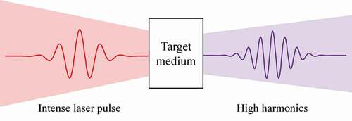
High harmonic generation (HHG) can be induced by focusing an intense laser onto either gas atoms [Citation1–5], solids [Citation6–11], or liquids [Citation12,Citation13], as sketched in . By invoking the so-called three-step model, the HHG process arising from gas atoms can be easily described [Citation5,Citation14]. This semiclassical approach successfully explains the main HHG features, and it has received numerous experimental validations [Citation15–17]. In short, an atomic electron, under the influence of an intense laser field, would undergo (i) ionization, (ii) acceleration, and (iii) recombination. The final step of the sequence is instrumental, and it is the source of several strong field-induced phenomena, being HHG one of the most prominent. Here, the energy gained by the electron during its motion in the laser continuum is converted into a high-energy photon upon recombination with the ground state where it started its laser-driven dynamics. Typically, due to the symmetry of the driving laser pulse and the target, only constructively interfered odd-order harmonics of the incoming laser wavelength are detected, while the even-order ones are strongly suppressed. The three-step model, however, describes solid-HHG only partially. This is because solid-HHG operates in a slightly different manner than gas-HHG [Citation18]. Since the inter-distance between the gaseous atoms is large enough, each atom in gas phase HHG can be thought of as a single independent HHG source. Atoms in a bulk solid, on the other hand, have much shorter interatomic spacing and interact strongly with other surrounding atoms. The strong interaction between atoms produces distinct features (e.g. the electronic band structure, the bandgap, the linear and nonlinear susceptibility, etc.) for each material, making the solid-HHG process analysis extremely complex.
Figure 1. Scheme of high-order harmonic generation. When an intense laser is focused on a target, atoms, molecules or bulk matter, high-order harmonics of the driving laser field, i.e. high energy photons, are generated
The ionization of electrons in atoms is the first step in all the strong-field phenomena. Atomic or molecular electrons could be laser-ionized mainly following two different pathways. The Keldysh parameter (), which is expressed as follows: [Citation19,Citation20]Footnote1
where is the binding energy of the electron in the atom and
the ponderomotive energy (
,
being the laser electric field peak strength and
the laser carrier frequency), is employed to discriminate the different ionization mechanisms. Here, the electron is ionized from the atom through (i) multiphoton ionization (perturbative process) in relatively low laser intensity (
) laser fields or (ii) tunneling ionization (non-perturbative process) in relatively strong laser intensity (
) laser fields. Thus, there exist prominent differences between high-order harmonics generated by these two distinct mechanisms. In the multiphoton (perturbative) regime, the intensity of the N-th order harmonic is proportional to the order of the process (e.g.
is proportional to
). On the other hand, within the tunneling (non-perturbative) regime, two unique features appear, namely (i) a plateau, i.e. a region in the HHG spectrum where the intensity of a set of harmonics is constant and (ii) a cutoff, i.e. there is no harmonic radiation beyond a particular harmonic order [Citation21].
From a macroscopic point of view, a smaller number of atoms in a given volume participate in the HHG process, when gas atoms are used as a nonlinear medium [Citation22–24] compared to solid materials. This is due to the fact that the atoms inside the solid are much more densely packed. In this way, higher conversion efficiency would be, in principle, achievable. There exists, however, a drawback: solid materials are unable to withstand the same laser intensity as gases.
The generation of high-order harmonics from solid samples has an extensive journey (for recent reviews see, e.g. [Citation25–27], and, for current developments in solid-HHG see, e.g. [Citation28–32]). In the early stages, a reflection-type setup was used for solid-HHG experiments [Citation6,Citation7,Citation33,Citation34], in which an intense laser beam falls obliquely on a solid target, and the generated high harmonics propagate along the reflection path. In 1977, N. H. Burnett et al. built a reflection-type setup using flat Al targets and a CO2 laser [Citation6]. They reported that non-perturbative high harmonics can be detected at the reflection path. However, the reflection-type setup has some disadvantages, such as the difficulties to align the incident beam and the effects the beam incident angle has on the light–matter interaction. These issues can be addressed by employing a transmission-type setup, in which the laser beam typically hits the solid target perpendicularly, and the generated high harmonics are measured along the transmission path. A. H. Chin et al. developed a transmission-type setup and conducted HHG experiments with a mid-infrared laser driving ZnSe and ZnTe samples in 2001 [Citation35]. They measured up to the seventh harmonic, which is slightly lower than the bandgap of such materials. Since this seminal experiment, the transmission-type setup has been widely used for solid-HHG investigations, considering it appears to be the easiest to implement. Advances in technology, such as the development of a titanium-sapphire laser (Ti:S laser) and improvements in the performance of vacuum pumps, have lifted the existing constraints, allowing for the development of very high power lasers in the visible portion of the electromagnetic spectrum as well as very efficient vacuum systems. Ghimire et al. reported what we could consider the first non-perturbative HHG experiment in solids. Here, a mid-infrared (
m) laser shone a ZnO sample, generating harmonics up to the 25th order, for the higher laser intensity used [Citation8]. The experiment confirmed several properties of the solid-HHG. According to these first findings, the high-energy cutoff increases proportional to the driving laser electric field strength, as shown in , b). This is in clear contrast to the HHG in gases, where the cutoff scales quadratically with the laser electric field strength [Citation4]. In addition, the conversion efficiency of each harmonic is dependent on the laser intensity. ) depicts the harmonic intensity from the 9th – to the 21st-order harmonics as a function of the driving laser intensity. As it can be seen, each harmonic intensity is approximately proportional to the order of the process in the perturbative regime (below 1.0 TW/cm2) and scales linearly with the driving laser intensity in the non-perturbative region (above 1.0 TW/cm2).
Figure 2. Measured high-order harmonic signals for ZnO driven by a mid-infrared (
m) laser source [Citation8]. (a) the HHG cutoff reaches up to the 17th (25th) order for a laser energy of 0.52 (2.63)
J. (b) The HHG cutoff increases linearly with the driving laser field strength in the range of 0.2 to 0.6 V/Å. (c) Measured intensity of the 9th – to 21st-order harmonics as a function of the driving laser intensity. Each harmonic intensity increases proportionally to the order of the process below 1.0 TW/cm2 and linearly to the driving laser intensity above 1.0 TW/cm2
![Figure 2. Measured high-order harmonic signals for ZnO driven by a mid-infrared (λ=3.25 μ m) laser source [Citation8]. (a) the HHG cutoff reaches up to the 17th (25th) order for a laser energy of 0.52 (2.63) μ J. (b) The HHG cutoff increases linearly with the driving laser field strength in the range of 0.2 to 0.6 V/Å. (c) Measured intensity of the 9th – to 21st-order harmonics as a function of the driving laser intensity. Each harmonic intensity increases proportionally to the order of the process below 1.0 TW/cm2 and linearly to the driving laser intensity above 1.0 TW/cm2](/cms/asset/25ec2d32-8b5a-4155-8776-da2c78074c63/tapx_a_2003244_f0002_oc.jpg)
In addition to the observations of high-order harmonics in ZnO [Citation8,Citation36–38], HHG experimental studies have been performed using a large set of materials with different bandgaps and properties (e.g. amorphous SiO2 [Citation39], GaSe [Citation9,Citation10,Citation40], MgO [Citation41–43], MgF2 [Citation44], Si [Citation45], sapphire [Citation46,Citation47], Quartz [Citation43], monolayer graphene [Citation48], MoS2 [Citation48,Citation49], WS2 [Citation50], and a WSe2 nano-sheet [Citation51]). ) depicts a table with a set of materials used in HHG experiments as a function of both the pump laser photon energy and high-harmonic cutoff [Citation52].
Figure 3. (a) The table represents a set of materials used in solid-HHG experiments, as a function of both the photon energy of the pump laser and the measured HHG cutoff [Citation52]. (b) HHG process in solids. When an intense laser is focused on a solid target, an electron moves from a valence band to a conduction band. The electron is accelerated along the conduction band landscape (intraband acceleration). Then it recombines with a hole on the valence band (interband transition). The high harmonics are emitted by both the electron-hole recombination (interband harmonics) and the accelerated motion of the electron (intraband harmonics)
![Figure 3. (a) The table represents a set of materials used in solid-HHG experiments, as a function of both the photon energy of the pump laser and the measured HHG cutoff [Citation52]. (b) HHG process in solids. When an intense laser is focused on a solid target, an electron moves from a valence band to a conduction band. The electron is accelerated along the conduction band landscape (intraband acceleration). Then it recombines with a hole on the valence band (interband transition). The high harmonics are emitted by both the electron-hole recombination (interband harmonics) and the accelerated motion of the electron (intraband harmonics)](/cms/asset/72da8736-f96e-4d58-a035-81cad5b965b6/tapx_a_2003244_f0003_oc.jpg)
In order to analyze the solid-HHG, various theoretical approaches have been proposed and adopted instead of the three-step model. For instance, we find a model including perspectives of electron trajectories [Citation53,Citation54], a nonrelativistic quantum-mechanical theory [Citation55], a two-band model [Citation56], an approach including propagation effects [Citation57], a Floquet-Bloch-based theory [Citation58], an inter- and intra-band dynamics approach [Citation59–61], a Wannier-Stark state-based approach [Citation62], an approach based on Bloch oscillations [Citation54,Citation63], a full quantum theory model with two conduction and three valence bands [Citation10], a model dealing with the semimetal regime [Citation64], a Wannier-Bloch approach [Citation65], a model including a detailed study of the dephasing time [Citation66], a model including allowing the electron to cross the first Brillouin zone [Citation9,Citation67], an approach incorporating the Berry curvature [Citation68], time-dependent density functional theory (TDDFT) simulations of atomic-like HHG [Citation69], an electron backscattering approach to model HHG from bilayer nanostructures [Citation70], several theoretical models based on the semiconductor Bloch equations (SBE) [Citation71–75], an injection-current-induced solid-HHG approach [Citation76] and models to deal with HHG from strongly-correlated or topological systems [Citation77,Citation78], among others.
When an intense laser is focused on a solid, the following processes induce solid-HHG [Citation79,Citation80]. Within a single electron picture, first, an electron in the solid is excited from a valence band to a conduction band by the intense laser field. Second, this excited electron is accelerated along the path of the conduction band (intraband acceleration), and it finally recombines with a hole on the valence band (interband transition), as depicted in ). The high-order harmonics are generated by these intra – or inter-band electron dynamics [Citation11,Citation38]. Since these electrons’ motions are significantly affected by the band structure envelope and band gap energy, both play a significant role in determining the properties of the emitted high-order harmonics.
Here, we describe several properties of solid-HHG, some of them clearly distinct from the ones of the gas-HHG. In solid crystals, the atoms are periodically arranged, therefore, they can have a geometrical symmetry and different conduction and valence band landscapes depending on the crystal orientations. Y. You et al. performed HHG experiments by focusing a linearly polarized infrared (
m) beam on a 001-cut MgO target having a fourfold geometrical symmetry [Citation41]. The high-order harmonic signals were then recorded as a function of the relative angle between the direction of the laser polarization and the crystal orientation of MgO, by rotating the crystal as shown in ). ) confirms that the measured high harmonic intensity exhibits a fourfold periodicity, which is the same as the one of the crystal symmetry. Additionally, H. Kim et al. conducted an analogous Ti:S laser (
nm) based HHG experiment with the C-plane (sixfold symmetry) and M-plane (fourfold symmetry) of sapphire ()) [Citation46]. Similarly, each measured high harmonic spectra exhibit the same periodicity as each crystal plane symmetry, as shown in , e). These results show that solid-HHG efficiency depends strongly on the crystal orientation; in other words, the band structure shape and bandgap energy play a fundamental role on the harmonic signal strength.
Figure 4. Crystal-orientation dependence in solid-HHG. (a) High-order harmonics are induced by focusing an infrared laser on 001-cut MgO, which has a 4-fold symmetry. (b) The HHG signals are recorded as a function of the relative angle between the laser polarization direction and the crystal orientation of the MgO. The result exhibits a 4-fold periodicity [Citation41]. (c) The C-plane and M-plane in sapphire have a 6-fold and 4-fold symmetry, respectively. (d, e) HHG from sapphire when it is driven by an intense Ti:S laser. The recorded HHG signals as a function of the laser polarization angle show a 6 – and 4-fold periodicity for the C-plane and M-plane orientations, respectively, which is the same as each crystal symmetry [Citation46]
![Figure 4. Crystal-orientation dependence in solid-HHG. (a) High-order harmonics are induced by focusing an infrared laser on 001-cut MgO, which has a 4-fold symmetry. (b) The HHG signals are recorded as a function of the relative angle between the laser polarization direction and the crystal orientation of the MgO. The result exhibits a 4-fold periodicity [Citation41]. (c) The C-plane and M-plane in sapphire have a 6-fold and 4-fold symmetry, respectively. (d, e) HHG from sapphire when it is driven by an intense Ti:S laser. The recorded HHG signals as a function of the laser polarization angle show a 6 – and 4-fold periodicity for the C-plane and M-plane orientations, respectively, which is the same as each crystal symmetry [Citation46]](/cms/asset/4ee59e13-5b95-481c-b337-01de64ee9251/tapx_a_2003244_f0004_oc.jpg)
Besides the crystalline-dependent HHG yields, the high harmonics generated from solids have several distinct features, in contrast to the gas phase HHG. In general, gas-phase HHG yields depend on the ellipticity of the driving laser fields [Citation81,Citation82]. K. S. Budil et al. performed a gas-HHG experiment of Xe, Ar, and Ne gases utilizing a pulse laser with a wavelength of 825 nm and analyzed the HHG yields for different ellipticities ()) [Citation81]. The intensity of each high-order harmonic radically decreases as the ellipticity increases. Numerically, the intensity of the 19th to the 63rd order harmonics generated from Ne is reduced by about thousand times when the ellipticity change from 0 to 0.4. This result could be explained as follows: the gas phase-HHG is driven by ionization, acceleration, and recombination of electrons. If a circularly polarized laser is shone to an atom, the electron’s trajectory is highly modified, resulting in a reduction of the final momentum of the accelerated electrons and suppressing the recombination probability with the parent ion.
Figure 5. Ellipticity dependence in gas- and solid-HHG. Experimentally measured HHG signals from Ne (gas) driven by a 825 nm wavelength laser (a) [Citation81], and ZnO driven by a mid-infrared laser (b) [Citation8], respectively. The HHG is recorded for different ellipticities. The overall HHG signals significantly decrease, when the ellipticity increases. Specifically, the 19th – to 63th-order (7th – to 13th-order) harmonics generated from Ne gas (ZnO) are reduced by about a thousand times (a few times) when the ellipticity changes from 0 to 0.5. (c) HHG signals generated from a monolayer graphene driven by a mid-infrared laser. This layered material has a zero bandgap. As an exceptional case, it is reported that the 9th-order harmonic intensity increases when the ellipticity increases from 0 to 0.32. This behaviour is attributed to the intrinsic properties of the monolayer graphene [Citation48]
![Figure 5. Ellipticity dependence in gas- and solid-HHG. Experimentally measured HHG signals from Ne (gas) driven by a 825 nm wavelength laser (a) [Citation81], and ZnO driven by a mid-infrared laser (b) [Citation8], respectively. The HHG is recorded for different ellipticities. The overall HHG signals significantly decrease, when the ellipticity increases. Specifically, the 19th – to 63th-order (7th – to 13th-order) harmonics generated from Ne gas (ZnO) are reduced by about a thousand times (a few times) when the ellipticity changes from 0 to 0.5. (c) HHG signals generated from a monolayer graphene driven by a mid-infrared laser. This layered material has a zero bandgap. As an exceptional case, it is reported that the 9th-order harmonic intensity increases when the ellipticity increases from 0 to 0.32. This behaviour is attributed to the intrinsic properties of the monolayer graphene [Citation48]](/cms/asset/bf5eca8d-5e27-4169-af7f-65d450541dee/tapx_a_2003244_f0005_oc.jpg)
Interestingly, solid-HHG efficiency seems to be less dependent on the ellipticity than the gas phase-HHG [Citation83]. ) represents the HHG of ZnO by using a mid-infrared laser at different ellipticities (, and
) [Citation8]. Even though the overall high-order harmonic yields in a solid decrease with an increase of the ellipticity, the actual amount at
is only a small factor, being only larger at the highest harmonic orders. Additionally, a distinct example of solid-HHG was reported by Yoshikawa et al. [Citation48]. They experimentally performed the HHG of zero bandgap monolayer graphene with a mid-infrared laser. ) represents the measured signals at the ellipticities of 0, 0.32, and 1. Surprisingly, the 9th-order harmonic intensity increases when the ellipticity changes from 0 to 0.32 due to the intrinsic zero bandgap property of the monolayer graphene. The different and intriguing ellipticity-dependent HHG yields in solids imply that the solid-HHG should be modelled differently than gas-phase HHG.
Breaking the symmetry in HHG is a crucial issue for generating even order harmonics or shorter XUV pulses. In solid-HHG, thin films are mainly used for this purpose. They tend to reduce the degradation of the driving laser field, and the detected HHG are mainly originated near the surface of the solid medium due to the re-absorption by the solid target. The re-absoption can be eased by using a nanostructure and engineering its geometry. For instance, H. Liu et al. induced high harmonics from an array of ridge waveguides with mid-infrared few-cycle femtosecond pulses [Citation28]. The harmonics generated at the ridges’ sidewalls make coupling with other harmonics generated in other sidewalls at the vacuum region between ridges. Then, the harmonics emission modulates depending on the waveguide length, ridge – and vacuum region-width, and the emission increases about 100-fold with respect to bulk Si, proving that such nanostructure geometry can alleviate the re-absorption leading to an enhancement in the harmonics transmission.
In a typical solid-HHG experiment, the thin film is usually located within the beam path and its surfaces are facing to the air or vacuum regions. At the interface, the symmetry of the material is broken by the change in their physical parameters. This symmetry breaking enables the observation of even-order harmonics and an increase in the HHG efficiency. Gao Yi et al. measured the 3rd – and 5th-order harmonics by focusing a near-infrared laser, with a wavelength of 1595 nm, in a stacked silicon wafer [Citation84]. The stacked wafers have microscopic interfaces, where the bulk symmetry breaking occurs (e.g. in the Si-air and Si-air-Si interfaces). They experimentally observed that the 3rd and 5th order harmonic yields are distinctly increased, when the beam is focused at these microscopic interfaces, as shown in .
Figure 6. Experiment showing symmetry breaking effects in solid-HHG [Citation84]. (a) Scheme of the experimental setup; 3rd- and 5th-order harmonics are induced by a focused near-infrared laser (1595 nm) in stacked silicon wafers. They have interfaces where the bulk symmetry breaking occurs (e.g. Si-air and Si-air-Si). The harmonics are recorded by moving the beam focusing position along the optical axis. (b) The intensity of the 3rd- and 5th-order harmonics increases when the focusing is positioned at the interfaces
![Figure 6. Experiment showing symmetry breaking effects in solid-HHG [Citation84]. (a) Scheme of the experimental setup; 3rd- and 5th-order harmonics are induced by a focused near-infrared laser (1595 nm) in stacked silicon wafers. They have interfaces where the bulk symmetry breaking occurs (e.g. Si-air and Si-air-Si). The harmonics are recorded by moving the beam focusing position along the optical axis. (b) The intensity of the 3rd- and 5th-order harmonics increases when the focusing is positioned at the interfaces](/cms/asset/ef22bf29-8818-497c-9b2e-008c781812f8/tapx_a_2003244_f0006_oc.jpg)
As was already stated, even-order harmonics can be generated due to the inherent properties of the solid targets or by breaking the symmetry between the solid and the laser field. H. Liu et al. demonstrated even-order solid-HHG by focusing a mid-infrared (0.30 eV) beam on a monolayer MoS2, a low-dimensional (i.e. 2D layered) material [Citation49]. , b) represents the measured high-order harmonics from both a monolayer and bulk MoS2, which corresponds to about a hundred MoS2 layers. Even though odd-order harmonics are detected in both cases, even-order harmonics are detected only at the monolayer MoS2. Thus, the generation of even-order harmonics could be induced by the inherent inversion symmetry breaking of the monolayer MoS2. Besides, symmetry breaking can be induced by different external stimuli. For example, Vampa et al. used a mid-infrared pump laser for solid-HHG on ZnO, while simultaneously illuminating the sample with a weaker second harmonic beam [Citation38]. The second harmonic field modifies the symmetry of the electron’s trajectory (i.e. symmetry breaking), resulting in an even-order harmonics generation, as shown in , d).
Figure 7. Symmetry breaking even-order harmonics generation in solids. (a, b) HHG are induced by focusing a near-infrared laser on a monolayer and bulk MoS2 [Citation49]. While the odd-order harmonics are detected for both cases, the even-order harmonics are detected only for the monolayer MoS2. The even-order harmonics generation is believed to be induced by the innate inversion symmetry breaking of the monolayer. (c, d) Simplified pictorial description for the electron’s trajectory during the HHG process; If only the fundamental beam is focused on a nonlinear target, the electron promoted to the conduction band travels along a symmetric trajectory (see red dashed lines on (c)). Because of the electron’s symmetric motion, only odd-order harmonics can be detected, not the even-order ones. Vampa et al. show odd – and even-order harmonics generation from ZnO driven by a focused mid-infrared pump laser join with its second, weaker, harmonic [Citation38]. Because the second harmonic beam modifies the symmetry of the electron trajectory, turning it slightly asymmetrical (i.e. symmetry breaking), even-order harmonics are visible (see blue solid lines on (c))
![Figure 7. Symmetry breaking even-order harmonics generation in solids. (a, b) HHG are induced by focusing a near-infrared laser on a monolayer and bulk MoS2 [Citation49]. While the odd-order harmonics are detected for both cases, the even-order harmonics are detected only for the monolayer MoS2. The even-order harmonics generation is believed to be induced by the innate inversion symmetry breaking of the monolayer. (c, d) Simplified pictorial description for the electron’s trajectory during the HHG process; If only the fundamental beam is focused on a nonlinear target, the electron promoted to the conduction band travels along a symmetric trajectory (see red dashed lines on (c)). Because of the electron’s symmetric motion, only odd-order harmonics can be detected, not the even-order ones. Vampa et al. show odd – and even-order harmonics generation from ZnO driven by a focused mid-infrared pump laser join with its second, weaker, harmonic [Citation38]. Because the second harmonic beam modifies the symmetry of the electron trajectory, turning it slightly asymmetrical (i.e. symmetry breaking), even-order harmonics are visible (see blue solid lines on (c))](/cms/asset/81cb3154-b9bd-4201-9161-18abbc2f1e3e/tapx_a_2003244_f0007_oc.jpg)
In condensed matter physics, it is essential to analyze the electronic band structure, in order to understand the materials’ physical/chemical properties. Angle-resolved photoemission spectroscopy (ARPES) is a technique that allows for reconstructing the band structure of materials by measuring the energies and momenta of the target material emitted photoelectrons. However, it only provides limited information about the band structure, such as the details of the valence band. Even though time-resolved angle-resolved photoemission spectroscopy [Citation85,Citation86] and angle-resolved inverse photoemission spectroscopy [Citation87,Citation88], which are pump-probe-based methods and the inverse process of ARPES, can be used for the reconstruction of the conduction band as alternatives, these methods require additional equipment such as pump – and probe-pulses as well as an electron beam source. Thereby, the properties of the conduction band typically rely on numerical simulations or limited experimental data. Since the excited electrons by the intense laser field in the solid undergo intra – and inter-band dynamics, the generated high-order harmonics will preserve information about both the valence and conduction band structures. Thus, solid-HHG could be applicable for investigating the material properties with unprecedented time and spatial resolutions. Some attempts have been already reported, aimed for the characterization of both the valence and conduction band structures using solid-HHG [Citation11,Citation80].
Vampa et al. demonstrated HHG using ZnO driven by a mid-infrared pump laser with a weak second-harmonic pulse as a perturbation [Citation80]. This setup enables the observation of odd – and even-order harmonics as a function of the delay between the fundamental and the second harmonic driven fields ()). As a result, they reconstructed the momentum-dependent band structure by using the HHG spectrum, which inherits information of the coherent motion of electron-hole pairs in the ZnO (see )).
Figure 8. Reconstruction of the electronic band structure in ZnO. Odd – and even-order harmonics are induced in ZnO, when driven by an intense mid-infrared pump laser, and a weaker second harmonic beam, treated as a perturbation [Citation80]. (a) The HHG signals are experimentally recorded as a function of the time delay between the fundamental and the second harmonic beams. (b) The experimentally measured and calculated optimum phases. (c) A reconstructed momentum-dependent band structure. Electrons in the first conduction band (blue line) recombine with holes in a split-off valence band (green line) generating the 10th – and 16th-order harmonics
![Figure 8. Reconstruction of the electronic band structure in ZnO. Odd – and even-order harmonics are induced in ZnO, when driven by an intense mid-infrared pump laser, and a weaker second harmonic beam, treated as a perturbation [Citation80]. (a) The HHG signals are experimentally recorded as a function of the time delay between the fundamental and the second harmonic beams. (b) The experimentally measured and calculated optimum phases. (c) A reconstructed momentum-dependent band structure. Electrons in the first conduction band (blue line) recombine with holes in a split-off valence band (green line) generating the 10th – and 16th-order harmonics](/cms/asset/d46b5e0f-07e3-4bec-92fb-e4c1aa32aa55/tapx_a_2003244_f0008_oc.jpg)
Solid-HHG can be used for very high spatial resolution imaging. H. Lakhotia et al. have measured HHG from MgF2, by focusing a few-cycle pulse, 5.5 fs, and a photon energy of 2 eV, with the polarization aligned along the and
crystal orientations, as shown in ) [Citation44]. The intensity of the high-order harmonics is closely linked to the laser polarization and the periodic potential in the crystal. Thus, the N-th order harmonic intensity (
) can be computed as follows
Figure 9. (a) Laser picoscopy setup. HHG signals are generated from MgF2 by a focused few-cycle pulse (5.5 fs, 2 eV). The beam polarization is aligned along the and
crystal orientations. (b, c) The blue lines represent the variation of the valence potential along the
and
directions, respectively. (d) The valence electron potential in MgF2 is retrieved with picometer accuracy [Citation44]
![Figure 9. (a) Laser picoscopy setup. HHG signals are generated from MgF2 by a focused few-cycle pulse (5.5 fs, 2 eV). The beam polarization is aligned along the ⟨110⟩ and ⟨100⟩ crystal orientations. (b, c) The blue lines represent the variation of the valence potential along the ⟨110⟩ and ⟨100⟩ directions, respectively. (d) The valence electron potential in MgF2 is retrieved with picometer accuracy [Citation44]](/cms/asset/e7586d35-5824-4c76-8e28-609c2d1d20f4/tapx_a_2003244_f0009_oc.jpg)
where is a unit vector along the laser polarization,
is the Bessel function of order
,
and
are the projections of the reciprocal space vectors and the Fourier components of the potential along the laser polarization vector, respectively. Thus, the structural information of MgF2 can be extracted from the generated high-order harmonics. From the measured HHG spectra, a 2D real-space potential map is retrieved with picometer (
m) accuracy, as shown in ).
In addition to the band structure reconstruction and high spatial resolution imaging in solids, solid-HHG has been used to extract the nonlinear susceptibility [Citation89] and characterize the real-time electron dynamics [Citation90,Citation91].
2. Nanophotonics-based high harmonic generation in solids
Surface plasmons (SP), the localized surface electromagnetic waves that propagate in a direction parallel to the metal/dielectric (or metal/vacuum) interface, can be induced by shining a strong laser pulse in a solid material. The SP is the collective charge oscillation resulting from the interaction of free electrons and light [Citation92]. Therefore, the SP enables a substantial enhancement and nanoscale spatial control of the incoming field. Several articles reported it is possible controlling the strength and spatial distribution of the SP field by engineering the geometry of nanostructures and a unique selection of metal/dielectric materials [Citation93–99]. Since the field enhancement by the SP is relatively high, it can be utilized for boosting solid-HHG. As is well-known, as higher the laser intensity, higher-order harmonics are generated. However, if the driving laser intensity is too strong beyond the damage threshold of the material, the sample could be deformed by various processes. For example, by multiphoton absorption. Here, multiple photons are simultaneously absorbed by the material when driven by a strong laser field and they can generate an electron-hole plasma, allowing the laser energy to deposit in the material [Citation100–102]. In addition, non-thermal process, i.e. electronic excitations by the ultrashort laser pulse, modifies the interatomic potential and destabilizes the crystal lattice, leading to the damage of the material [Citation103,Citation104]. These processes distinctively contribute to the deformation, depending on the experimental conditions such as the band gap of material, pulse duration, and laser intensity, among others. Therefore, introducing plasmonic nanostructures to induce HHG in solids enables the observation of higher harmonic orders as well as enhanced high-order harmonic yields, with less damage to the material.
Vampa et al. demonstrated SP-assisted HHG using bar-shaped nano-antennas in silicon [Citation97]. The plasmonic sample is prepared by fabricating an array of 20-nm-thick gold nano-antennas on a 500-nm-thick silicon film, grown on a sapphire substrate (see the inset of )). The plasmonic resonant conditions are numerically simulated and controlled by the size of the nanostructures for a given resonance wavelength and polarization. , c) shows the calculated intensity enhancement for a laser pulse with
m and 100 fs, polarized parallel and perpendicular with respect to the
crystal orientation. The field intensity around the nano-antenna edges is enhanced by about 400 times at the parallel polarization condition (on resonance), but SP enhancement is negligible at the perpendicular polarization condition (off-resonance). Here, considerable intensity enhancement leads to the generation of higher order harmonics with larger yields. They experimentally observed the 5th-, 7th-, and 9th-order harmonics by focusing an infrared laser with an intensity of
W/cm2, as shown in ). ) shows the measured 5th-, 7th-, and 9th-order harmonic yields from nano-antennas and bare Si at parallel and perpendicular laser polarizations. Despite the small SP enhanced volume covered by the antennas (8%), harmonic emission is increased by about 5 to 10 times for the parallel polarization, compared to the perpendicular polarization and the bare Si. This implies that the high-harmonic emission density, in consideration of a SP volume of
nm2, is increased by
times with respect to the bulk.
Figure 10. Plasmonic-assisted HHG [Citation97] (a) scheme of the experimental setup. The inset represents the fabricated nanostructure sample. HHG is induced by infrared pulses (
m and 100 fs). (b, c) Calculated intensity enhancement in the designed nano-antenna for parallel and perpendicular polarizations with respect to the
crystal orientation, respectively. (d) Measured high-order harmonic emission for the parallel (red) and the perpendicular (green) polarizations. The black line represents the HHG from a bare Si, without including the nano-antenna
![Figure 10. Plasmonic-assisted HHG [Citation97] (a) scheme of the experimental setup. The inset represents the fabricated nanostructure sample. HHG is induced by infrared pulses (λc=2.1 μ m and 100 fs). (b, c) Calculated intensity enhancement in the designed nano-antenna for parallel and perpendicular polarizations with respect to the ⟨110⟩ crystal orientation, respectively. (d) Measured high-order harmonic emission for the parallel (red) and the perpendicular (green) polarizations. The black line represents the HHG from a bare Si, without including the nano-antenna](/cms/asset/bc38a21d-89e7-4bde-ace0-2520354ab4d8/tapx_a_2003244_f0010_oc.jpg)
S. Han et al. demonstrated different types of SP-assisted HHG, using funnel-waveguide nanostructures [Citation96]. In the funnel structure, the propagating SP fields, the surface plasmon polaritons (SPP), are induced, and these fields could be guided up to the sharp tip of the structure resulting in a strong SP focused at a single spot. ) depicts the SP guiding nanostructure made of gold and sapphire in a funnel shape. When the incident beam propagates from the bottom of the structure, the SP field focuses on the metal-sapphire interface, where the Au-covered apex is cut and flattened. The numerically estimated intensity enhancement, when the driving laser ( nm and 12 fs) is incident on the nanostructure, is shown in ). The intensity enhancement is obtained by monitoring the XY-plane on the sapphire tip and the cross-section of the XZ-plane. The intensity enhancement factor around the tip is approximately 100 times. ) represents the measured HHG from the nanostructure sample and a bare sapphire structure for two different laser intensities, 0.42 and 1.58 TW/cm2. Surprisingly, the same high harmonic cut-off is observed, around at the 13th order, even when the input laser intensity at the nanostructure sample is 3.76 times lower than that of the bare case. Not only the bar-shaped nano-antenna and funnel-waveguide nanostructures discussed here are used, but various plasmonic nanostructures (e.g. bow-ties [Citation93], waveguides [Citation94], nanoparticles coupled to a plasmonic antenna [Citation95]) are candidates for a possible way to improve the solid-HHG efficiency as well.
Figure 11. Plasmonic-assisted HHG [Citation96] (a) Scheme of SPP-assisted HHG with a funnel-waveguide nanostructure. (b) The fabricated funnel-waveguide nanostructures. (c) Calculated intensity enhancement for the xy-plane on the sapphire tip (left) and cross section of the xz-plane (right). (d) HHG from the nanostructure sample and a bare sapphire driven by a laser intensity of 0.42 and 1.58 TW/cm2, respectively
![Figure 11. Plasmonic-assisted HHG [Citation96] (a) Scheme of SPP-assisted HHG with a funnel-waveguide nanostructure. (b) The fabricated funnel-waveguide nanostructures. (c) Calculated intensity enhancement for the xy-plane on the sapphire tip (left) and cross section of the xz-plane (right). (d) HHG from the nanostructure sample and a bare sapphire driven by a laser intensity of 0.42 and 1.58 TW/cm2, respectively](/cms/asset/f9f70b44-0b52-4a9d-86d8-e8b64f7427ec/tapx_a_2003244_f0011_oc.jpg)
Even when the SP-based HHG has several benefits compared to bare solid-HHG, the SP enhancement requires noble metals (e.g. Au, Ag, Pt) at the visible and infrared light. Then, the thermal damage of the SP nanostructures is unavoidable. Different resonant nanostructure systems, with three or more levels, have been reported to exhibit Fano-resonance-like electromagnetically induced transparency (EIT), with a sharp transmission peak occurring at the resonance wavelength [Citation105–111]. EIT is known to be caused by the interference of quantum states, which significantly alters the optical properties of the medium. Thus, EIT can significantly improve the nonlinear matter-light interaction processes [Citation112]. H. Liu et al. demonstrate enhanced-HHG using optically resonant dielectric nanostructures that induce EIT [Citation106]. As shown in ), the resonant nanostructures are made up of bar antennas and disk resonators. Light with a resonance wavelength (approximately 2320 nm) and adequate polarization can induce EIT. The bar forms a bright mode, which can directly interact with the resonant light, linearly polarized parallel to the bar. The disk forms a dark mode, which is no resonant to the driving light. Instead, it can interact with the bright mode via a near-field coupling. As shown in ), the combination of the bar and the disk creates a three-level Fano-resonance system that enables EIT. ) shows the calculated and measured transmission around the resonance wavelength. The sharp transmission peak (i.e. EIT) induced by the near-field coupling between the dark and the bright modes is clearly observed.
Figure 12. Fano-resonant silicon metasurface [Citation106] (a) The fabricated metasurface consists of bar antennas and disk resonators. (b) The bar forms a bright mode and can be excited by resonant wavelength light with polarization parallel to the bars. The disk forms a dark mode and can interact with the bright mode via near-field coupling. The combination of the bar and the disk forms a three-level Fano-resonant system. (c) Calculated and measured transmission in the resonant metasurface around the resonant wavelength. A sharp Fano-resonance peak is observed. (d, e) Calculated mode amplitude of the bar and the disk. (f) Time evolution of the excited fields at the bar center, disk center, disk edge (corresponding to B, C, and E points on (d, e)), and unpatterned Si for comparison. (g) Measured HHG driven by a laser intensity of 0.071 TW/cm2 with parallel and perpendicular polarizations, respectively. (h) Measured HHG yields of the 5th-, 7th-, and 9th-order harmonic as a function of the excitation intensity
![Figure 12. Fano-resonant silicon metasurface [Citation106] (a) The fabricated metasurface consists of bar antennas and disk resonators. (b) The bar forms a bright mode and can be excited by resonant wavelength light with polarization parallel to the bars. The disk forms a dark mode and can interact with the bright mode via near-field coupling. The combination of the bar and the disk forms a three-level Fano-resonant system. (c) Calculated and measured transmission in the resonant metasurface around the resonant wavelength. A sharp Fano-resonance peak is observed. (d, e) Calculated mode amplitude of the bar and the disk. (f) Time evolution of the excited fields at the bar center, disk center, disk edge (corresponding to B, C, and E points on (d, e)), and unpatterned Si for comparison. (g) Measured HHG driven by a laser intensity of 0.071 TW/cm2 with parallel and perpendicular polarizations, respectively. (h) Measured HHG yields of the 5th-, 7th-, and 9th-order harmonic as a function of the excitation intensity](/cms/asset/75311385-bc6b-4019-9194-fea5fdcaaa17/tapx_a_2003244_f0012_oc.jpg)
The calculated mode amplitudes of the bar and disk are shown in , e). Furthermore, ) illustrates the time evolution of the excitation field at the bar center, disk center, disk edge (corresponding to points of B, C, and E in , e)), and unpatterned Si. Distinct resonant features are found at the patterned Si. Because the energy interchange, due to the Fano resonance, between the bar and the disk structure, a more prolonged field oscillation survival leads to an enhancement of the HHG yield. HHG from nanostructure patterned and unpatterned samples, by focusing a light source of 2320 nm in wavelength, 70 fs pulse duration and 0.071 TW/cm2 laser intensity, were experimentally observed. When the laser polarization is parallel to the long axis of the bar-shaped structure (on Fano resonance), higher and enriched harmonic emission, up to the 11th-order are recognized, while the HHG cut-off reaches only the 5th order, for unpatterned Si and non-resonant polarization conditions. ) plots a comparison of the HHG yields for the patterned and unpatterned samples. The patterned sample exhibits a significantly enhanced HHG emission compared to the unpatterned sample. Furthermore, the enhancement factor appears to be affected by the intensity of the laser; the enhancement factor increases as the intensity decreases.
Introducing nanostructures for solid-HHG appears as an attractive option, considering they improve the HHG with a unique control of the light-electron dynamics in solids. They require, however, important engineering and design efforts. For instance, metal-based plasmonics nanostructures are weak for thermal damage, depending on the structural geometries, and the metal structures at the intensity needed for HHG can be easily deformed or ablated in a short period of time [Citation96,Citation113]. The all-dielectric nanostructures with higher damage thresholds could be candidates for nanostructure-based HHG experiments, but it requires a large field enhancement for the generation of higher harmonic orders [Citation106].
The electron beam lithography and focused ion beam (FIB) milling are general ways for nanostructure fabrication. However, the fabricated samples by these methods have intrinsic fabrication limitations, causing structural deviations from the numerically designed shapes. In addition, a portion of focused ions could be implanted on the fabrication sample during the FIB milling process. The implanted ions could modify the atomic lattice, electron structure, or work as dopants in the sample, leading to unexpected results [Citation114,Citation115]. These imperfections lead to a degradation of the field enhancement and, consequently, to the HHG performance [Citation116]. The usage of focused He-ion beam milling or single-crystalline solids could be a solution for resolving these issues. The focused ion beam milling by the He, instead of Ga, can fabricate higher-resolution nanostructures [Citation117–120]. The sample quality of the fabricated nanostructures depends on the surface roughness and grain size of the solid medium [Citation121,Citation122]. It is reported that nanostructures fabricated using single-crystalline gold flakes show better sample quality, with finer features, than the ones obtained from multi-crystalline gold films.
3. Spatio-temporal control of HHG with geometrically modified surfaces in solids
Conventional refractive optics are not readily applicable for controlling the spatial properties (e.g. steering the propagation direction or direct focusing) of the generated high-order harmonics. This is because the absorption coefficient of most refractive optical materials at the high-order harmonic wavelengths is relatively high, making it impossible to observe their transmission in a medium having a thickness of the order of a millimeter. In that sense, solid-HHG is mostly considered as a surface effect. Thus, the direct shaping or engraving of the solid target surfaces enable a spatial control of the HHG without the need for additional optics.
H. Kim et al. reported that the propagation direction of extreme ultraviolet (EUV) high-order harmonics could be steered by shaping the surface of a solid target [Citation46]. They experimentally monitored the propagation direction of the generated high-order harmonics at bulk sapphire with a flat and sloped surface at a angle. In both cases, high-order harmonics up to the 13th order (61 nm) are generated by focusing ultrashort near-infrared pulses (
nm, 12 fs, 1.31 TW/cm2), with a convergence angle of
. In addition, the propagation direction of the EUV beams at free space was measured by varying the distance between the sapphire and a microchannel plate (MCP) detector. In the case of the flattened sapphire substrate, the generated EUV beam propagates normal to the surface with a divergence angle of
as shown in , c).
Figure 13. Steering beam propagation of extreme ultraviolet (EUV) harmonics by shaping a surface of a solid target [Citation46]. EUV high-order harmonics are induced at both the sapphire samples with a flat surface and the sloped surface cut at an angle of , by focusing near-infrared pulses (
nm, 12 fs, 1.31 TW/cm2) with a convergence angle of
. Beam propagation profiles of the EUV high-order harmonics generated at the flat surface (a) and the sloped surface (b), respectively. The profiles are recorded by changing the gap distance between the sapphire and a microchannel plate. Schematic of the beam propagation of the EUV beam generated at the flat surface (c) and the sloped surface (d), respectively
![Figure 13. Steering beam propagation of extreme ultraviolet (EUV) harmonics by shaping a surface of a solid target [Citation46]. EUV high-order harmonics are induced at both the sapphire samples with a flat surface and the sloped surface cut at an angle of 30∘, by focusing near-infrared pulses (λc=800 nm, 12 fs, 1.31 TW/cm2) with a convergence angle of 25∘. Beam propagation profiles of the EUV high-order harmonics generated at the flat surface (a) and the sloped surface (b), respectively. The profiles are recorded by changing the gap distance between the sapphire and a microchannel plate. Schematic of the beam propagation of the EUV beam generated at the flat surface (c) and the sloped surface (d), respectively](/cms/asset/b9405891-e19c-4a9b-a32e-13af29726e27/tapx_a_2003244_f0013_oc.jpg)
For the sloped surface sample, the pumped near-infrared pulse should be refracted at an angle of , following the Snell’s law (, d)). Here, the angle of incidence is
, considering the sapphire’s refractive index is 1.76 at 800 nm. Interestingly, the refractive angle at the emitted high-order harmonic beam does not follow the Snell’s law. At these generated EUV wavelengths, the refractive index of the sapphire is from 0.8 to 2.2.
It was shown that the emitted EUV beams originate in an ultra-thin sapphire layer of the sloped surface, with a thickness comparable to the pump laser wavelength. As a result, the HHG propagates at the refracted pump beam propagation direction. This study shows that the spatial control of the solid-HHG could be possible by shaping the surface of the solid target. Similarly, M. Sivis et al. demonstrated diffraction-limited self-focusing of the generated harmonics using a silicon integrated Fresnel zone plate (FZP) target [Citation114]. Unlike conventional refractive lenses, the FZP enables light to focus by diffraction by the concentric rings, with varying sizes. Each ring functions as an independent high-order harmonics source and diffractive element, and its structural parameters follow the phase-matching condition of at the focal point, where
is the wavelength of each high-order harmonic, and
is an integer. As a result, each high-order harmonic constructively interferes at a different focal point, resulting in focused high-order harmonic spots. The introduction of an engraved gallium-implanted FZP pattern on a Si substrate would allow the self-focusing in high-order harmonic devices. A scanning electron microscope (SEM) image of a fabricated gallium-implanted FZP pattern (darker area) is shown in ). In this structure, high-order harmonics up to the 9th-order (250 nm) was observed by focusing ultrashort infrared pulses having a wavelength of 2.25
m, pulse duration of 70 fs, and a peak intensity of about
W/cm2.
Figure 14. (a) Schematic of an integrated Fresnel zone plate (FZP) target in silicon leading to self-focusing of the generated high-order harmonics [Citation114]. (b) A SEM image of a fabricated gallium-implanted FZP pattern (darker area) in Si. High-order harmonics up to the 9th-order (250 nm) are induced by focusing ultrashort infrared pulses (
m, 70 fs, above
W/cm2). For imaging, the signals are recorded with a high numerical aperture objective lens (63x, NA = 0.75) and a bandpass filter. (c) The measured 3rd-order harmonic emission profile on the FZP pattern plane. The inset shows an SEM image of the FZP pattern corresponding to its profile. (d, e) Focus scans of the 3rd – and 5th-order harmonic, respectively, as a function of the distance to the pattern plane. The scans are obtained by moving the collecting objective lens relative to the FZP pattern. (f) Measured beam widths at each focal point; the 3rd – and 5th-order harmonics are focused up to diffraction-limited spot sizes, corresponding to each wavelength and diffraction order
![Figure 14. (a) Schematic of an integrated Fresnel zone plate (FZP) target in silicon leading to self-focusing of the generated high-order harmonics [Citation114]. (b) A SEM image of a fabricated gallium-implanted FZP pattern (darker area) in Si. High-order harmonics up to the 9th-order (250 nm) are induced by focusing ultrashort infrared pulses (λc=2.25 μ m, 70 fs, above 1012 W/cm2). For imaging, the signals are recorded with a high numerical aperture objective lens (63x, NA = 0.75) and a bandpass filter. (c) The measured 3rd-order harmonic emission profile on the FZP pattern plane. The inset shows an SEM image of the FZP pattern corresponding to its profile. (d, e) Focus scans of the 3rd – and 5th-order harmonic, respectively, as a function of the distance to the pattern plane. The scans are obtained by moving the collecting objective lens relative to the FZP pattern. (f) Measured beam widths at each focal point; the 3rd – and 5th-order harmonics are focused up to diffraction-limited spot sizes, corresponding to each wavelength and diffraction order](/cms/asset/d8cc46e7-079e-4eb8-ac6f-57e62c3089c9/tapx_a_2003244_f0014_oc.jpg)
The spatial distribution of each high-order harmonic is analyzed using a high numerical aperture objective lens (63x, NA = 0.75) with a bandpass filter. The measured 3rd-order harmonic emission profile on the patterned plane is shown in ). A significant 3rd-order harmonic emission is observed at the gallium-implanted patterned area compared to the Si area, implying that the patterned area dominates the HHG by ion implantation. Like gallium ions in a p-type semiconductor, implanted gallium ions can act as electron acceptors, adding a positive charge density to the valence band. Furthermore, crystal defects during the implantation process (such as vacancies and interstitials) add up different states within the bandgap. The added states can alter the solid-HHG process, resulting in an enhancement of the HHG yield [Citation115].
The spatial distribution of the 3rd- and 5th-order harmonics along the optical axis were investigated by positioning an objective lens along the optical axis (, e)). The 3rd- and 5th-order harmonics were then concentrated to near the diffraction-limited spot sizes for each wavelength and diffraction order ()). The FZP-based HHG shows promising self-focusing capabilities and could pave the way for compact and integrated HHG devices.
In light of various phase-controlled solid-HHG concepts, metasurfaces could be applicable for future HHG platforms. A metasurface consists of nanostructures able to modify the phase of the incident beam, similar to a spatial light modulator, in a way that each of the N-th nanostructure constituting the metasurface can be considered as a nanometer-scale HHG source, with a phase retardation of . A variety of nanostructures (e.g. V-antenna [Citation123,Citation124], elliptical nanopillars [Citation125], nanoholes [Citation126], nanofins [Citation127]) have been used for inducing a phase retardation (
) depending on the rotation angle of the rods or the ellipticity of the nanopillar. This microscopic phase control by nanostructures could enable a unique macroscopic spatial control of solid-HHG.
M. Khorasaninejad et al. demonstrated that metalens composed of titanium dioxide nanofins allow for diffraction-limited focusing [Citation127]. Depending on the arranged angle, each nanofin introduces a geometrical phase to the incident beam. For example, a nanofin arranged at an angle of induces a geometric phase of
, as shown in ). The centers of the nanofins are arranged at regular intervals and the angles of each nanofin are chosen such that the phase difference at the designed focal point between the beams coming from each nanofin is
, where
is the design wavelength, and
is an integer (see )). Consequently, the beams constructively interfere at the focal point leading to a beam focusing. , d) shows optical and SEM images of the fabricated metalens, respectively. Diffraction-limited focal spots of the metalens (NA = 0.8) were evaluated with a commercially available high-NA objective lens (100x Nikon CFI 60; NA = 0.8) for a designed wavelength of 532 nm (, f)). The metalens have a nearly diffraction-limited focal spot size of 375 nm at FWHM, which is 1.6 times smaller than the objective lens’s focal spot size of 600 nm. This shows the superior focusing capability of the metalens. Since the metasurface is based on nanostructures, it can be used for the enhanced generation of nonlinear effects (e.g. HHG) and, simultaneously, to control the spatial properties of the emitted high-order harmonics. When the second or third harmonics are induced in the metasurface, the nanostructures can induce a geometrical phase in the transmitted harmonics, enabling the control of their spatial properties, as in the case of the metalens. In practice, metasurfaces that provide self-controlling (e.g. beam propagation steering [Citation128] and direct beam focusing [Citation126]) for the second and third harmonics have been demonstrated. However, to the best of our knowledge, such metasurface-based HHG has not been reported yet. In this sense, we believe that metasurfaces configure a promising tool to self-controlling the HHG sources, like the solid target with the sloped surface and the gallium-implanted FZP target.
Figure 15. Metalens enabling diffraction-limited focusing [Citation127]. (a) Pancharatnam-Berry phase; a nanofin arranged at an angle of induces a geometrical phase of
to the incident beam. (b) Schematic of a metalens composed of nanofins. Optical (c) and SEM (d) images of a fabricated matelens. Focal spot profiles of 532-nm light focused by the metalens (e) and by a commercial objective lens (100x Nikon CFI 60; NA = 0.8) (f) are recorded with a collecting objective lens (100x, NA = 0.9), tube lens, and CMOS camera. The focal spot sizes at FWHM are 375 and 600 nm, respectively
![Figure 15. Metalens enabling diffraction-limited focusing [Citation127]. (a) Pancharatnam-Berry phase; a nanofin arranged at an angle of θ induces a geometrical phase of 2θ to the incident beam. (b) Schematic of a metalens composed of nanofins. Optical (c) and SEM (d) images of a fabricated matelens. Focal spot profiles of 532-nm light focused by the metalens (e) and by a commercial objective lens (100x Nikon CFI 60; NA = 0.8) (f) are recorded with a collecting objective lens (100x, NA = 0.9), tube lens, and CMOS camera. The focal spot sizes at FWHM are 375 and 600 nm, respectively](/cms/asset/86a7df73-4908-40a3-8aba-cc0ed0377449/tapx_a_2003244_f0015_oc.jpg)
4. Conclusions and Perspectives
In this contribution, we review the solid-HHG from the early studies to the recent trends. The solid-HHG presents different features than gas-HHG. Since the interatomic distance in a solid is much shorter than the gas phase, the solid atoms strongly interact with their surrounding atoms, resulting in a distinct environment for the electron dynamics. Thus, various models (e.g. a two-band model [Citation56] and a full quantum theory model [Citation10]) have been proposed and appropriately utilized to understand and analyze the solid-HHG, for a large set of target and laser parameters.
The solid-HHG process is closely linked to the physical properties of both the material and the driving laser’s parameters (e.g. band structure, crystallinity, laser wavelength, ellipticity or polarization, etc.). For example, each intraband and interband transition contributes differently to the HHG, depending on the ellipticity of the driving laser [Citation129]. Thus, high-order harmonics show fingerprints of the electron’s behavior in the solid, thereby providing insights to disentangle its complex dynamics. Thus, for instance, from the solid-HHG spectrum, it is possible to retrieve both the solid band structure [Citation67,Citation130,Citation131] and its associated geometrical structure [Citation43,Citation132] as well as to characterize the interatomic potential [Citation43,Citation133]. Furthermore, the momentum-dependent band structure of ZnO [Citation80] and the valence electron potential in MgF2 [Citation44] were reconstructed by using the high-order harmonics generated in these solid samples. Furthermore, even-order harmonics are produced from the surface of an intrinsic topological insulator (BiSbTeSe2), when it is driven by intense mid-infrared pulses. The even-order harmonics are unique footprints of strong-field-driven helical Dirac fermions in the topological surface states and can be helpful to understand the complex dynamics of the electron in those topological surface states [Citation134].
In solid-HHG, the HHG cutoff is usually proportional to the peak strength of the laser electric field. Additionally, in most of the cases, it is the solid damage threshold the limiting factor to reach larger HHG cutoffs. The introduction of nanostructures into the solid-HHG enables an enhanced high harmonic emission, reaching higher-order harmonics and at the same time minimizing the material damage. For example, higher HHG cutoffs and yields, compared to the bare solid-HHG, are observed in both the bar-shaped nano-antenna setups, due to the plasmonic field enhancement [Citation97] and in the metasurface composed of bar antennas and disk resonators setups, due to a Fano-resonance [Citation106].
The sloped surface [Citation46] and the integrated FZP target in silicon [Citation114] showed the potential for controlling the spatial properties (e.g. steering the beam propagation or the direct focusing) of the generated harmonics in solids. In addition to these methods, metasurfaces composed by nanostructures are expected to be bifunctional HHG devices in the not so far future [Citation126–128].
Compared with gas phase-HHG, solid-HHG is a fascinating way to generate high-order harmonics with relatively low-intensity laser pulses. There exist, however, several limitations to still rely on conventional gas phase HHG in attosecond science. Nevertheless, the solid-HHG is opening a new era within the ultrafast optical technologies with compact XUV sources (e.g. imaging with picometer accuracy, extracting physical parameters of a solid, attosecond pulse generation, full reconstruction of the electronic band structure, etc.).
Acknowledgments
This work was supported by the National Research Foundation of Korea (NRF) grant funded by the Korea government (MSIT) (No. 2020R1C1C100769112) and by of the international cooperation program managed by the National Research Foundation of Korea (2019K2A9A1A0607115712). M. F. C. acknowledges the Czech Science Foundation (GACR) (Grant number: 20-24805J) and the Guangdong Province Science and Technology Major Project (Future functional materials under extreme conditions - 212019071820400001).
Disclosure statement
No potential conflict of interest was reported by the authors.
Notes
1. Atomic units are used, unless otherwise stated, i.e. the electron rest mass, , the elementary charge,
, and the reduced Planck’s constant,
, are all equal to 1.
References
- Baltuška A, Udem T, Uiberacker M, et al. Attosecond control of electronic processes by intense light fields. Nature. 2003;421:611–29.
- Paul PM, Toma ES, Breger P, et al. Observation of a train of attosecond pulses from high harmonic generation. Science. 2001;292:1689–1692.
- Schafer KJ, Kulander KC. High harmonic generation from ultrafast pump lasers. Phys Rev Lett. 1997;78:638–641.
- Krause JL, Schafer KJ, Kulander KC. High-order harmonic generation from atoms and ions in the high intensity regime. Phys Rev Lett. 1992;68:3535.
- Lewenstein M, Balcou P, Ivanov MY, et al. Theory of high-harmonic generation by low-frequency laser fields. Phys Rev A. 1994;49:2117.
- Burnett NH, Baldis HA, Richardson MC, et al. Harmonic generation in co2 laser target interaction. Appl Phys Lett. 1977;31:172–174.
- Carman RL, Forslund DW, Kindel JM. Visible harmonic emission as a way of measuring profile steepening. Phys Rev Lett. 1981;46:29.
- Ghimire S, DiChiara AD, Sistrunk E, et al. Observation of high-order harmonic generation in a bulk crystal. Nat Phys. 2011;7:138–141.
- Schubert O, Hohenleutner M, Langer F, et al. Sub-cycle control of terahertz high-harmonic generation by dynamical Bloch oscillations. Nat Phot. 2014;8:119–123.
- Hohenleutner M, Langer F, Schubert O, et al. Real-time observation of interfering crystal electrons in high-harmonic generation. Nature. 2015;523:572–575.
- Luu TT, Garg M, Kruchinin SY, et al. Extreme ultraviolet high-harmonic spectroscopy of solids. Nature. 2015;521:498–502.
- DiChiara AD, Sistrunk E, Miller TA, et al. An investigation of harmonic generation in liquid media with a mid-infrared laser. Opt Exp. 2009;17:20959–20965.
- Luu TT, Yin Z, Jain A, et al. Extreme–ultraviolet high–harmonic generation in liquids. Nat Commun. 2018;9:1–10.
- Corkum PB. Plasma perspective on strong-field multiphoton ionization. Phys Rev Lett. 1993;71:1994.
- Schafer KJ, Yang B, DiMauro LF, et al. Above threshold ionization beyond the high harmonic cutoff. Phys Rev Lett. 1993;70:1599.
- Heyl CM, Güdde J, Höfer U, et al. Spectrally resolved maker fringes in high-order harmonic generation. Phys Rev Lett. 2011;107:033903.
- He L, Lan P, Zhang Q, et al. Spectrally resolved spatiotemporal features of quantum paths in high-order-harmonic generation. Phys Rev A. 2015;92:043403.
- Garg M, Kim HY, Goulielmakis E. Ultimate waveform reproducibility of extreme-ultraviolet pulses by high-harmonic generation in quartz. Nat Phot. 2018;12:291–296.
- Keldysh LV. Ionization in the field of a strong electromagnetic wave. Sov Phys JETP. 1965;20:1307–1314.
- Reiss HR. Unsuitability of the keldysh parameter for laser fields. Phys Rev A. 2010;82:023418.
- Boyd RW. Nonlinear optics. Fourth ed. Cambridge: Academic Press; 2020.
- Sivis M, Duwe M, Abel B, et al. Nanostructure-enhanced atomic line emission. Nature. 2012;485:E1–E2.
- Raschke MB. High‐harmonic generation with plasmonics: feasible or unphysical? Ann Phys. 2013;525:A40–A42.
- Sivis M, Duwe M, Abel B, et al. Extreme-ultraviolet light generation in plasmonic nanostructures. Nat Phys. 2013;9:304–309.
- Yu C, Jiang S, Lu R. High order harmonic generation in solids: a review on recent numerical methods. Adv Phys-X. 2019;4:1562982.
- Kruchinin SY, Krausz F, Yakovlev VS. Colloquium: strong-field phenomena in periodic systems. Rev Mod Phys. 2018;90:021002.
- Huttner U, Kira M, Koch SW. Ultrahigh off‐resonant field effects in semiconductors. Laser Photonics Rev. 2017;11:1700049.
- Liu H, Vampa G, Zhang JL, et al. Beating absorption in solid-state high harmonics. Commun Phys. 2020;3:1–6.
- Korobenko A, Rashid S, Heide C, et al. Generation of structured coherent extreme ultraviolet beams from an mgo crystal. Opt Exp. 2021;29:24161–24168.
- Schmid CP, Weigl L, Grössing P, et al. Tunable non-integer high-harmonic generation in a topological insulator. Nature. 2021;593:385–390.
- Heinrich T, Taucer M, Kfir O, et al. Chiral high-harmonic generation and spectroscopy on solid surfaces using polarization-tailored strong fields. Nat Commun. 2021;12:1–7.
- Li J, Lu J, Chew A, et al. Attosecond science based on high harmonic generation from gases and solids. Nat Commun. 2020;11:1–13.
- Von der Linde D, Engers T, Jenke G, et al. Generation of high-order harmonics from solid surfaces by intense femtosecond laser pulses. Phys Rev A. 1995;52:R25.
- Norreys PA, Zepf M, Moustaizis S, et al. Efficient extreme UV harmonics generated from picosecond laser pulse interactions with solid targets. Phys Rev Lett. 1996;76:1832.
- Chin AH, Calderón OG, Kono J. Extreme midinfrared nonlinear optics in semiconductors. Phys Rev Lett. 2001;86:3292.
- Ghimire S, DiChiara AD, Sistrunk E, et al. Redshift in the optical absorption of ZnO single crystals in the presence of an intense midinfrared laser field. Phys Rev Lett. 2011;107:167407.
- Wang Z, Park H, Lai YH, et al. The roles of photo-carrier doping and driving wavelength in high harmonic generation from a semiconductor. Nat Commun. 2017;8:1–7.
- Vampa G, Hammond TJ, Thiré N, et al. Linking high harmonics from gases and solids. Nature. 2015;522:462–464.
- You YS, Yin Y, Wu Y, et al. High-harmonic generation in amorphous solids. Nat Commun. 2017;8:1–5.
- Langer F, Hohenleutner M, Huttner U, et al. Symmetry-controlled temporal structure of high-harmonic carrier fields from a bulk crystal. Nat Phot. 2017;11:227–231.
- You YS, Reis DA, Ghimire S. Anisotropic high-harmonic generation in bulk crystals. Nat Phys. 2017;13:345–349.
- You YS, Wu M, Yin Y, et al. Laser waveform control of extreme ultraviolet high harmonics from solids. Opt Lett. 2017;42:1816–1819.
- Lu J, Cunningham EF, You YS, et al. Interferometry of dipole phase in high harmonics from solids. Nat Phot. 2019;13:96–100.
- Lakhotia H, Kim HY, Zhan M, et al. Laser picoscopy of valence electrons in solids. Nature. 2020;583:55–59.
- Vampa G, Hammond TJ, Thiré N, et al. Generation of high harmonics from silicon. arXiv. 2016;1605:06345.
- Kim H, Han S, Kim YW, et al. Generation of coherent extreme-ultraviolet radiation from bulk sapphire crystal. ACS Photonics. 2017;4:1627–1632.
- Kim YW, Shao TJ, Kim H, et al. Spectral interference in high harmonic generation from solids. ACS Photonics. 2019;6:851–857.
- Yoshikawa N, Tamaya T, Tanaka K. High-harmonic generation in graphene enhanced by elliptically polarized light excitation. Science. 2017;356:736–738.
- Liu H, Li Y, You YS, et al. High-harmonic generation from an atomically thin semiconductor. Nat Phys. 2017;13:262–265.
- Yoshikawa N, Nagai K, Uchida K, et al. Interband resonant high-harmonic generation by valley polarized electron–hole pairs. Nat Commun. 2019;10:1–7.
- Langer F, Hohenleutner M, Schmid CP, et al. Lightwave-driven quasiparticle collisions on a subcycle timescale. Nature. 2016;533:225–229.
- Ghimire S, Reis DA. High-harmonic generation from solids. Nat Phys. 2019;15:10–16.
- Vampa G, McDonald CR, Orlando G, et al. Semiclassical analysis of high harmonic generation in bulk crystals. Phys Rev B. 2015;91:064302.
- Luu TT, Wörner HJ. High-order harmonic generation in solids: a unifying approach. Phys Rev B. 2016;94:115164.
- Gupta AK, Alon OE, Moiseyev N. Generation and control of high-order harmonics by the interaction of an infrared laser with a thin graphite layer. Phys Rev B. 2003;68:205101.
- McDonald CR, Vampa G, Corkum PB, et al. Interband Bloch oscillation mechanism for high-harmonic generation in semiconductor crystals. Phys Rev A. 2015;92:033845.
- Ghimire S, DiChiara AD, Sistrunk E, et al. Generation and propagation of high-order harmonics in crystals. Phys Rev A. 2012;85:043836.
- Faisal FHM, Kamiński JZ. Floquet-Bloch theory of high-harmonic generation in periodic structures. Phys Rev A. 1997;56:748.
- Golde D, Meier T, Koch SW. High harmonics generated in semiconductor nanostructures by the coupled dynamics of optical inter- and intraband excitations. Phys Rev B. 2008;77:075330.
- Golde D, Meier T, Koch SW. Microscopic analysis of high‐harmonic generation in semiconductor nanostructures. Phys Status Solidi C. 2009;6:420–423.
- Vampa G, McDonald CR, Orlando G, et al. Theoretical analysis of high-harmonic generation in solids. Phys Rev Lett. 2014;113:073901.
- Higuchi T, Stockman MI, Hommelhoff P. Strong-field perspective on high-harmonic radiation from bulk solids. Phys Rev Lett. 2014;113:213901.
- Wu M, Ghimire S, Reis DA, et al. High-harmonic generation from Bloch electrons in solids. Phys Rev A. 2015;91:043839.
- Tamaya T, Ishikawa A, Ogawa T, et al. Diabatic mechanisms of higher-order harmonic generation in solid-state materials under high-intensity electric fields. Phys Rev Lett. 2016;116:016601.
- Osika EN, Chacón A, Ortmann L, et al. Wannier-Bloch approach to localization in high-harmonics generation in solids. Phys Rev X. 2017;7:021017.
- Vampa G, McDonald C, Fraser A, et al. High-harmonic generation in solids: bridging the gap between attosecond science and condensed matter physics. IEEE J Sel Top Quantum Electron. 2015;21:1–10.
- Du TY, Tang D, Huang XH, et al. Multichannel high-order harmonic generation from solids. Phys Rev A. 2018;97:043413.
- Yue L, Gaarde MB. Imperfect recollisions in high-harmonic generation in solids. Phys Rev Lett. 2020;124:153204.
- Tancogne-Dejean N, Rubio A. Atomic-like high-harmonic generation from two-dimensional materials. Sci Adv. 2018;4:eaao5207.
- Yu C, Jiang S, Wu T, et al. Higher harmonic generation from bilayer nanostructures assisted by electron backscattering. Phys Rev B. 2020;102:241407.
- Jiang S, Yu C, Chen J, et al. Smooth periodic gauge satisfying crystal symmetry and periodicity to study high-harmonic generation in solids. Phys Rev B. 2020;102:155201.
- Jiang S, Gholam-Mirzaei S, Crites E, et al. Crystal symmetry and polarization of high-order harmonics in zno. J Phys B. 2019;55:225601.
- Jiang S, Chen J, Wei H, et al. Role of the transition dipole amplitude and phase on the generation of odd and even high-order harmonics in crystals. Phys Rev Lett. 2018;120:253201.
- Jiang S, Wei H, Chen J, et al. Effect of transition dipole phase on high-order-harmonic generation in solid materials. Phys Rev A. 2017;96:053850.
- Yu C, Zhang X, Jiang S, et al. Dependence of high-order-harmonic generation on dipole moment in Sio2 crystals. Phys Rev A. 2016;94:013846.
- Jürgens P, Liewehr B, Kruse B, et al. Origin of strong-field-induced low-order harmonic generation in amorphous quartz. Nat Phys. 2020;16:1035–1039.
- Imai S, Ono A, Ishihara S. High harmonic generation in a correlated electron system. Phys Rev Lett. 2020;124:157404.
- Silva REF, Jiménez-Galán A, Amorim B, et al. Topological strong-field physics on sub-laser-cycle timescale. Nat Phot. 2019;13:849–854.
- Ghimire S, Ndabashimiye G, DiChiara AD, et al. Strong-field and attosecond physics in solids. J Phys B: At Mol Opt Phys. 2014;47:204030.
- Vampa G, Hammond TJ, Thiré N, et al. All-optical reconstruction of crystal band structure. Phys Rev Lett. 2015;115:193603.
- Budil KS, Salières P, L’Huillier A, et al. Influence of ellipticity on harmonic generation. Phys Rev A. 1993;48:R3437.
- Burnett NH, Kan C, Corkum PB. Ellipticity and polarization effects in harmonic generation in ionizing neon. Phys Rev A. 1995;51:R3418.
- Ndabashimiye G, Ghimire S, Wu M, et al. Solid-state harmonics beyond the atomic limit. Nature. 2016;534:520–523.
- Gao Y, Lee H, Jiao J, et al. Surface third and fifth harmonic generation at crystalline si for non-invasive inspection of si wafer’s inter-layer defects. Opt Exp. 2018;26:32812–32823.
- Haight R. Electron dynamics at surfaces. Surf Sci Rep. 1995;21:275–325.
- Kim S, Yoshizawa S, Ishida Y, et al. Robust protection from backscattering in the topological insulator bi 1.5 sb 0.5 te 1.7 se 1.3. Phys Rev Lett. 2014;112:136802.
- See AK, Thayer M, Bartynski RA. Angle-resolved inverse-photoemission study of the nearly perfect tio 2 (110) surface. Phys Rev B. 1993;47:13722.
- Sato H, Arita M, Utsumi Y, et al. Conduction-band electronic structure of 1 t-tas 2 revealed by angle-resolved inverse-photoemission spectroscopy. Phys Rev B. 2014;89:155137.
- Han S, Ortmann L, Kim H, et al. Extraction of higher-order nonlinear electronic response in solids using high harmonic generation. Nat Commun. 2019;10:1–6.
- Sommer A, Bothschafter EM, Sato SA, et al. Attosecond nonlinear polarization and light–matter energy transfer in solids. Nature. 2016;534:86–90.
- Garg M, Zhan M, Luu TT, et al. Multi-petahertz electronic metrology. Nature. 2016;538:359–363.
- Stockman MI. Nanoplasmonics: the physics behind the applications. Phys Today. 2011;64:39–44.
- Kim S, Jin J, Kim YJ, et al. High-harmonic generation by resonant plasmon field enhancement. Nature. 2008;453:757–760.
- Park IY, Kim S, Choi J, et al. Plasmonic generation of ultrashort extreme-ultraviolet light pulses. Nat Phot. 2011;5:677–681.
- Aouani H, Rahmani M, Navarro-Cía M, et al. Third-harmonic-upconversion enhancement from a single semiconductor nanoparticle coupled to a plasmonic antenna. Nat Nanotechnol. 2014;9:290–294.
- Han S, Kim H, Kim YW, et al. High-harmonic generation by field enhanced femtosecond pulses in metal-sapphire nanostructure. Nat Commun. 2016;7:1–7.
- Vampa G, Ghamsari BG, Mousavi SS, et al. Plasmon-enhanced high-harmonic generation from silicon. Nat Phys. 2017;13:659–662.
- Franz D, Kaassamani S, Gauthier D, et al. All semiconductor enhanced high-harmonic generation from a single nanostructured cone. Sci Rep. 2019;9:1–7.
- Wen Y, Zhou J. Artificial generation of high harmonics via nonrelativistic Thomson scattering in metamaterial. Research. 2019;2019:8959285.
- Schaffer CB, Brodeur A, Mazur E. Laser-induced breakdown and damage in bulk transparent materials induced by tightly focused femtosecond laser pulses. Meas Sci Technol. 2001;12:1784.
- Li C, Feng D, Jia T, et al. Ultrafast dynamics in ZnO thin films irradiated by femtosecond lasers. Solid State Commun. 2005;136:389–394.
- Paschotta R. Article on multiphoton absorption. In: Encyclopedia of laser physics and technology. 1st ed. 2008. Wiley-VCH. p. 1. ISBN 978-3-527-40828-3.
- Sundaram SK, Mazur E. Inducing and probing non-thermal transitions in semiconductors using femtosecond laser pulses. Nat Mater. 2002;1:217–224.
- Medvedev N, Milov I. Nonthermal phase transitions in metals. Sci Rep. 2020;10:1–9.
- Boller KJ, Imamoğlu A, Harris SE. Observation of electromagnetically induced transparency. Phys Rev Lett. 1991;66:2593.
- Liu H, Guo C, Vampa G, et al. Enhanced high-harmonic generation from an all-dielectric metasurface. Nat Phys. 2018;14:1006–1010.
- Zhang S, Genov DA, Wang Y, et al. Plasmon-induced transparency in metamaterials. Phys Rev Lett. 2008;101:047401.
- Liu N, Hentschel M, Weiss T, et al. Three-dimensional plasmon rulers. Science. 2011;332:1407–1410.
- Yang Y, Kravchenko II, Briggs DP, et al. All-dielectric metasurface analogue of electromagnetically induced transparency. Nat Commun. 2014;5:1–7.
- Yang Y, Wang W, Boulesbaa A, et al. Nonlinear fano-resonant dielectric metasurfaces. Nano Lett. 2015;15:7388–7393.
- Limonov MF, Rybin MV, Poddubny AN, et al. Fano resonances in photonics. Nat Phot. 2017;11:543–554.
- Fleischhauer M, Imamoğlu A, Marangos JP. Electromagnetically induced transparency: optics in coherent media. Rev Mod Phys. 2005;77:633.
- Pfullmann N, Waltermann C, Kovaev M, et al. Nano-antenna-assisted harmonic generation. Appl Phys B. 2013;113:75–79.
- Sivis M, Taucer M, Vampa G, et al. Tailored semiconductors for high-harmonic optoelectronics. Science. 2017;357:303–306.
- Rimini E. Ion implantation: basics to device fabrication. New York: Springer US; 1995.
- Park J, Lee H, Gliserin A, et al. Spectral shifting in extraordinary optical transmission by polarization-dependent surface plasmon coupling. Plasmonics. 2020;15:489–494.
- Hlawacek G, Veligura V, van Gastel R, et al. Helium ion microscopy. J Vac Sci Technol B. 2014;32:020801.
- Allen FI, Velez NR, Thayer RC, et al. Gallium, neon and helium focused ion beam milling of thin films demonstrated for polymeric materials: study of implantation artifacts. Nanoscale. 2019;11:1403–1409.
- Boden S, Moktadir Z, Bagnall D, et al. Focused helium ion beam milling and deposition. Microelectron Eng. 2011;88:2452–2455.
- He S, Tian R, Wu W, et al. Helium-ion-beam nanofabrication: extreme processes and applications. Int J Extrem Manuf. 2021;3:012001
- Huang JS, Callegari V, Geisler P, et al. Atomically flat single-crystalline gold nanostructures for plasmonic nanocircuitry. Nat Commun. 2010;1:150.
- Chew SH, Gliserin A, Choi S, et al. Large-area grain-boundary-free copper films for plasmonics. Appl Surf Sci. 2020;521:146377.
- Yu N, Genevet P, Kats MA, et al. Light propagation with phase discontinuities: generalized laws of reflection and refraction. Science. 2011;334:333–337.
- Stolt T, Kim J, Héron S, et al. Backward phase-matched second-harmonic generation from stacked metasurfaces. Phys Rev Lett. 2021;126:033901.
- Wang L, Kruk S, Koshelev K, et al. Nonlinear wavefront control with all-dielectric metasurfaces. Nano Lett. 2018;18:3978–3984.
- Chen J, Wang K, Long H, et al. Tungsten disulfide–gold nanohole hybrid metasurfaces for nonlinear metalenses in the visible region. Nano Lett. 2018;18:1344–1350.
- Khorasaninejad M, Chen WT, Devlin RC, et al. Metalenses at visible wavelengths: diffraction-limited focusing and subwavelength resolution imaging. Science. 2016;352:1190–1194.
- Li G, Zhang S, Zentgraf T. Nonlinear photonic metasurfaces. Nat Rev Mater. 2017;2:1–14.
- Tancogne-Dejean N, Mücke OD, Kärtner FX, et al. Ellipticity dependence of high-harmonic generation in solids originating from coupled intraband and interband dynamics. Nat Commun. 2017;8:745.
- Luu TT, Wörner HJ. Measurement of the berry curvature of solids using high-harmonic spectroscopy. Nat Commun. 2018;9:1–6.
- Yu C, Jiang S, Wu T, et al. Two-dimensional imaging of energy bands from crystal orientation dependent higher-order harmonic spectra in h-bn. Phys Rev B. 2018;98:085439.
- Wang Z, Jiang S, Yuan G, et al. Strain effect on the orientation-dependent harmonic spectrum of monolayer aluminum nitride. Sci China Phys Mech. 2020;63:1–7
- You YS, Cunningham E, Reis DA, et al. Probing periodic potential of crystals via strong-field re-scattering. J Phys B. 2018;51:114002.
- Bai Y, Fei F, Wang S, et al. High-harmonic generation from topological surface states. Nat Phys. 2021;17:311–315.