
 ?Mathematical formulae have been encoded as MathML and are displayed in this HTML version using MathJax in order to improve their display. Uncheck the box to turn MathJax off. This feature requires Javascript. Click on a formula to zoom.
ABSTRACT
Nonlinear frequency generation at the nanoscale is a hot research topic which is gaining increasing attention in nanophotonics. The generation of harmonics in subwavelength volumes is historically associated with the enhancement of electric fields in the interface of plasmonic structures. Recently, new platforms based on high-index dielectric nanoparticles have emerged as promising alternatives to plasmonic structures for many applications. By exploiting optically induced electric and magnetic response via multipolar Mie resonances, dielectric nanoelements may lead to innovative opportunities in nanoscale nonlinear optics. Dielectric optical nanoantennas enlarge the volume of light–matter interaction with respect to their plasmonic counterpart, since the electromagnetic field can penetrate such materials, and therefore producing a high throughput of the generated harmonics. In this review, we first recap recent developments obtained in high refractive index structures, which mainly concern nonlinear second order effects. Moreover, we discuss configurations of dielectric nano-devices where reconfigurable nonlinear behavior is achieved. The main focus of this work concerns efficient Sum Frequency Generation in dielectric nano-platforms. The reported results may serve as a reference for the development of new nonlinear devices for nanophotonic applications.
GRAPHICAL ABSTRACT
I. Introduction
Nowadays, nonlinear generation of light from nano-devices is a strategic topic in nanophotonics [Citation1–5]. The main reason for this success is related to the different behavior observed in materials at the nanometer-scale as compared to the macroscopic phenomena [Citation6,Citation7]. This difference has been firstly observed in studies based on metallic – i.e. plasmonic – nanostructures. In these platforms, the harmonic process is enhanced by the presence of surface plasmon resonances at the fundamental frequency of the pump as well as the frequency of the generated harmonics [Citation8,Citation9]. Several approaches have been successfully implemented and have also enlightened that the main limitation in terms of nonlinear generation efficiency is related to the high dissipative losses of metals in the infrared and optical range [Citation10–12]. Therefore, overcoming such limitation is essential for realizing efficient nonlinear platforms at the nanoscale. A promising alternative to overcome this drawback is the use of dielectric resonator antennas that have previously been designed in the microwave and radio-frequency range and have recently been extended to optical frequencies [Citation13–19]. A key feature of dielectric nanoparticles is that they can exhibit electric, magnetic and toroidal dipolar resonances while concurrently attain very low intrinsic losses. Starting from the optimization of a single isolated nano-resonators [Citation20,Citation21], the research has moved to the design of optimized 2D arrangements of nano-elements, also named metasurfaces [Citation22,Citation23]. Such platforms are periodic arrays of scattering nano-elements whose dimensions and periods are generally smaller than the operating wavelength. In particular, dielectric metasurfaces are compact structures yielding strong enhancement of the driving fields, which makes them a versatile platform to boost, control and modulate harmonics and other nonlinear processes at the nanoscale [Citation24,Citation25]. Recently, Second – and Third- Harmonic Generation (SHG, THG) have been achieved in Aluminium Gallium Arsenide (AlGaAs), Gallium Arsenide (GaAs), Lithium Niobate (LiNbO3) and Silicon (Si) metasurfaces [Citation26–36]. Since the efficiency of a nonlinear phenomenon decreases with increasing nonlinearity order, SHG and THG represent the two major elastic contributions among the nonlinear optical processes. In more details, in the SHG process, two photons of frequency ω are annihilated, and a photon of frequency 2ω is simultaneously created in a single quantum-mechanical process. When the optical field incident upon a nonlinear optical medium consists of two distinct frequency components, the process is regarded as Sum Frequency Generation (SFG). SFG process is analogous to that of SHG, except that in the SFG the two input waves are at different frequencies. For this reason, it is conversely possible to state that the SHG is a degenerate case of the SFG process, where the input beams have the same frequency [Citation37]. Most important, in SFG, by properly selecting the input frequencies, it is possible to generate light in the desired wavelength range with an additional degree of freedom. This degree of freedom is related to the polarization of the input beams, which may be co-polarized, cross-polarized or any case in between, thus affecting the nonlinear response in different way.
This review is organized as follow: in Section II we report and describe recent achievements in terms of second-order nonlinear process in nano-structured dielectric materials. A brief overview of the main results in this field is given and a summary of reconfigurable SHG metasurfaces is presented. The discussion continues in Section III, where the nonlinear process of SFG is described both in an isolated nano-element and in a dielectric metasurface configuration, as well as infrared up-conversion imaging applications (Section IV). Finally, Section V is devoted to conclusions and future perspectives.
II. SHG in dielectric nano-structures
In this section, we discuss SHG in dielectric metasurfaces by focusing mainly on AlGaAs nano-resonators as the unitary cell of the metasurface arrangements. Although other materials, such as GaP [Citation38,Citation39], GaAs [Citation36] and LiNbO3 have been proposed for enhanced SHG [Citation40–46], AlGaAs has been widely used due to its high second-order nonlinear susceptibility (χ(2)), its negligible two-photon absorption in the Infra-Red (IR) spectral range (for specific aluminum concentration) and its low losses in the IR [Citation47–49]. In 2016, Gili and coworkers demonstrated an efficient SHG of about 10−5 (more than 3 orders of magnitude with respect to the plasmonic counterpart [Citation1]) originated from an isolated AlGaAs nano-pillar when illuminated with a pump beam at 1.5 μm and intensity of 1 GW/cm2 [Citation50]. In this pioneering work, such a record SHG efficiency, is achieved by designing the geometrical dimensions of the pillar in order to fulfill a magnetic dipolar resonance at the fundamental wavelength, see . In recent years, numerous works have been proposed with the goal of maximizing the SHG conversion efficiency in AlGaAs nanostructures [Citation51,Citation52]. For this purpose, anapole and Bound States In the Continuum (BIC) conditions have been extensively exploited [Citation53–62]. The so called anapole condition could be interpreted as the concurrently excitation of an electric dipole and a toroidal dipole moment with the same amplitude but in phase opposition. The equivalent radiation patterns of the two contributions produce an effectively destructive interference in the far-field, leading to the radiationless nature of the anapole [Citation63]. Such phenomenum has been demonstrated in different spectral regions, spanning from microwave to near-infrared and visible frequencies. In dielectric metasurfaces, the fulfillment of the anapole condition is not only associated with the suppression of far-field radiation but also enhancements in near-field energy, which facilitate and boost the harmonic generation efficiency [Citation55,Citation59]. For instance, in [Citation53], it is reported that in an AlGaAs dimer platforms, the near-field coupling can be translated into further degrees of freedom to change the polarization state and the radiation diagram of the second-harmonic field. The nonlinear efficiency can also be strongly enhanced by the use of BIC modes. Traditionally, the physics of BIC was well-known in atomic physics, acoustic and hydrodynamics [Citation64–66]. Recently, such concept has also been exploited in nonlinear nanophotonics because it can be used to obtain extremely high-quality factors for optical metasurfaces or subwavelength individual resonators [Citation67]. Instead of increasing the geometrical dimensions to excite, for example, high Q-factor whispering gallery modes, one can take advantages of the excitation of BIC even in subwavelength structures. The basic notion of the bound states in the continuum is vanishing coupling between the resonant mode and all radiation channels of the surrounding space. Two main classes of BIC can be distinguished: symmetry-protected and accidental BIC. The symmetry-protected BIC is reached when the spatial symmetry of the mode is fully mismatched with the symmetry of the outgoing radiating waves [Citation68–70]. On the contrary, the accidental BIC is obtained by the continuous tuning of one (or more) system parameter until an accidental vanishing of the coupling coefficient is reached [Citation71–73]. The dramatic Q-factor enhancement at the BIC condition represents a key aspect for nonlinear optics, revealing unconventional perspectives for active and passive metastructures at the nanoscale. The main reason is that nonlinear harmonic generation in subwavelength high refractive index resonators is not limited by phase-matching but it is mainly controlled by strong electromagnetic field confinement at the involved resonances. Since the SH process is proportional to the Q-factor of the fundamental resonance, an enhancement of the latter will dramatically increase the total SHG efficiency. In this context, a huge increase of the generation efficiency in terms of SHG coming from and individual AlGaAs nanoantennas tuned to the BIC regime has been recently investigated and demonstrated [Citation54]. Apart from efficiency, the emission properties of the SHG signal have also been deeply studied and several solutions to obtain the nonlinear signal along the normal direction have been designed and experimentally verified [Citation74–80]. More recently, the tunability and reconfigurability of the emitted SH light have been addressed. For this purpose, the use of anisotropic surrounding materials such as Liquid Crystals (LCs) has been proposed to achieve kHz modulation rates in metasurfaces composed of AlGaAs nanocylinders enclosed by E7 nematic LC (Merck Licristal). In [Citation81] it has been predicted that, by reversing the LC orientation with a realistic voltage bias, a modulation of the total power and of the emission pattern of the SH is achievable in the optimized metasurface. Since the mechanism is based on the rotation of large (few nm) molecules to switch the LC state, the modulation rate is inherently low (few kHz). Faster SH modulation rates can be achieved by employing thermo-optical effects. The optically tunable control of SHG in all-dielectric nanoresonators has been proposed in [Citation82], achieving a modulation rate up to MHz range. By exploiting a control beam that is absorbed by the nanoantenna, the refractive index of the dielectric element is thermo-optically tuned. Finally, the induced variation of the refractive index results in the amplitude modulation of the SH signal. Modulation of the SH efficiency up to 60% is measured for a modest localized temperature increase of about 40 K. This huge tunability at the single meta-atom level has motivated the investigation of SH thermo-optical meta-devices [Citation83]. Higher nonlinear modulation rates of a few MHz can be achieved by working with Phase-Change Materials around their transition temperature [Citation84,Citation85]. Finally, let us mention that ultrafast modulation rates have also been successfully proposed and investigated. In this context, nonlinear absorption and refraction or electric field-induced SHG in centrosymmetric materials have been studied [Citation86–89]. A summary depicting the aforementioned solutions for reconfigurable nonlinear modulation is shown in .
Figure 1. (a) Electric field enhancement in an AlGaAs-on-AlOx nanopillar with radius r = 200 nm and height h = 400 nm, excited by a plane wave at 1550 nm. Inset: SHG conceptual scheme, with two photons of frequency ω being annihilated, and a photon being simultaneously created at 2ω in a single quantum-mechanical process. (b) Measured and (c) calculated SHG vs. r, for h = 400 nm and 1.6 GW/cm2 pump intensity. Adapted from [Citation50].
![Figure 1. (a) Electric field enhancement in an AlGaAs-on-AlOx nanopillar with radius r = 200 nm and height h = 400 nm, excited by a plane wave at 1550 nm. Inset: SHG conceptual scheme, with two photons of frequency ω being annihilated, and a photon being simultaneously created at 2ω in a single quantum-mechanical process. (b) Measured and (c) calculated SHG vs. r, for h = 400 nm and 1.6 GW/cm2 pump intensity. Adapted from [Citation50].](/cms/asset/4e928c96-f61d-4a8b-b799-2d20f1a51ec1/tapx_a_2022992_f0001_oc.jpg)
Figure 2. An illustration of the SH modulation rates in dielectric platform based on different mechanisms. Adapted from [Citation90].
![Figure 2. An illustration of the SH modulation rates in dielectric platform based on different mechanisms. Adapted from [Citation90].](/cms/asset/d8db940f-e7c4-49ac-ad63-bc6fc51cede7/tapx_a_2022992_f0002_oc.jpg)
We believe that these recent developments open new avenues for optical/quantum communication and computing, virtual or augmented reality, imaging and holography. Since the above brief summary just aims to point out the potential of nonlinear SHG-based dielectric nanodevices, a more complete overview can be found in Refs. [Citation90–92].
A further technological boost is given by SFG in dielectric metasurfaces. Therefore, the following sections will cover this new research field, demonstrating the huge potential of the SFG nonlinear process from basic research to practical imaging applications.
III. SFG in dielectric nanoresonators
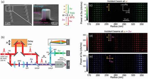
In this section, we discuss the recent achievements in SFG coming from a single isolated nano-antenna [Citation93]. We consider an isolated Nano Disk, ND, made of Al0.18Ga0.82As with a fixed height equal to 400 nm and radius, r, in the range 165 nm – 365 nm. The NDs are fabricated through electron-beam lithography and are layered over an AlOx substrate (refractive index of 1.6), see ). The NDs axes are oriented along the [001] crystal direction and are arranged in a 2D-matrix with period of 3 μm, long enough for the inter-particle coupling to be considered null. The incident pump beams at frequencies ω1 and ω2 are used to achieve, through the AlGaAs bulk χ(2), a SFG signal at frequency ω3 = ω1+ ω2. The incident pump at ω1 consists of a laser source that emits femtosecond pulses with a repetition rate equal to 80 MHz, centered at an angular frequency ω that corresponds to a wavelength of 1554 nm. The second incident source at ω2 is obtained by duplicating in frequency the pump beam at ω1 = ω. A beta barium borate crystal is used to obtain via SHG the second incident excitation which thus has a frequency of 2ω. The temporal delay between the two pulse trains is governed by a delay line in the ω beam path. It is straightforward to note that, for the specific choice of the incident frequency, the SFG signal is emitted at ω3 = 3ω that also corresponds to the frequency of the THG, see the energy diagram in ). Thus, for the specific selected condition, the SFG and THG signals are degenerate in frequency. A schematic of the implemented experimental setup is illustrated in ). The incident light pulses at ω and 2ω are combined and focused onto the sample via a 0.85 numerical aperture (NA) air microscope objective. The time-averaged powers of the incident pulses is respectively equal to Pavg(ω) = 384 μW and Pavg(2ω) = 192 μW. The generated nonlinear emission at 3ω is collected in a backscattering configuration through the same objective and optically filtered to remove unwanted spectral components. Finally, the emitted photon flux and the corresponding average power is measured using a single-photon avalanche photodiode. summarize the confocal maps detected at 3ω by scanning the sample under the laser beam via a piezoelectric microscope stage. Along the x direction, 10 nominally identical replicas of the same NDs are reported while the radius of the ND increases in steps of 6 nm along the y direction. In particular, ) reports the 3ω detected signal when the sample is excited solely by the pulse at ω. Instead, ) and (e) report the case when the sample is concurrently excited by pulses at ω and 2ω at co- and cross-polarized incidence, respectively.
Figure 3. (a) Scanning Electron Micrograph image of the fabricated resonators with a pitch of 3 μm and a magnified view of an individual nano-disk as indicated by the white frame. The colored area indicates the result of the fabrication steps: the AlGaAs nano-disk is in between a underlying transition layer and the overlaying HSQ resist. The right panel shows a graphical representation of the two nonlinear processes involved: the THG and the SFG. When the time delay between the two input pulses is zero, the SFG is maximized, and it adds to the always present THG which is only due to the pump at ω. (b) A schematic of the experimental set-up. BS indicates a 50:50 beam splitter, SPF the short-pass filter, BPF the band-pass filter, DMSP the dichroic mirror short-pass, DMLP the dichroic mirror long-pass and FM the flip mirror. (c-e) Experimental confocal raster scans of the cylinder array where the power detected at 3ω is depicted in false colors. The arrows indicate the polarization of the two pumps: a pulsed beam at ω alone (c) or superimposed to a pulsed beam at 2ω with either co- (d) or cross- (e) polarization. The AlGaAs crystalline axis orientation is shown as an inset in (c).
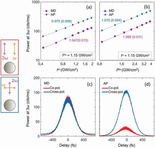
All three maps (see ) show a resonant behavior around the NDs with radii of 200 nm and 335 nm. In particular, the resonance around r = 200 nm is almost equally excited by the different configurations of the incident pump polarizations. In contrast, around r = 335 nm, the maximum of the nonlinear signal for co-polarized pumps is associated to a dip in the case of cross-polarized incidence (see maps d and e for comparison). elucidates the experimental results, stating that the measured nonlinear signal originates from the SFG process at 3ω = ω + 2ω. The figure reports the measured emitted power at 3ω as a function of the intensity of one of the incident pumps, while the power of the other one is maintained constant. A linear trend is observed for both magnetic dipole (MD) and anapole (AP) resonances, and for both co- and cross-polarized excitations, hence confirming the SFG nature of the process. This corroborates that the measured signal is due to the SFG process at 3ω = ω + 2ω. Nonlinear mixing has also been observed in the time domain by varying the time delay between the pulsed pumps at ω and 2ω, as shown in (c) & (d). The measured temporal traces present a temporal correlation peak arising from a flat THG baseline, which is produced by the ω beam alone. In this case, the experimental delay traces do not show temporal interference between the SFG and THG signals even if both are emitted at the same frequency equal to 3ω. This is due to spatial symmetries that forbid observing temporal interference in the far-field. For more details, the interested reader is referred to [Citation93].
Figure 4. (a,b) Measured nonlinear emission coming from an isolated single nano-disk as a function of the pump intensity at (a) ω and (b) 2ω when fixing the other pump intensity to the value reported in the insets. MD refers to cylinders exhibiting magnetic resonance (radius 200 nm) while AP indicates nano-disk exhibiting the anapole condition (radius 335 nm). The fitting values of the power are reported beside each line, with the uncertainty in brackets. (c,d) Delay traces recorded on a single nano-disk having a radius of (c) 200 nm and(d) 335 nm. The pumps have polarization as indicated in the legends and intensities I(ω) = 0.79 GW/cm2 and I(2ω) = 1.6 GW/cm2. The left panels display a sketch of the two experimental incident configurations of the pumps.
To further understand this dependence, theoretical simulations have been performed using Comsol Multiphysics. The resonators have been modeled as NDs with a fixed height (equal to 400 nm) and different radii in the range of 165 nm – 365 nm, as the fabricated ones. Firstly, the linear behavior is analyzed by numerical predictions. By performing a multipolar decomposition of the linear scattered light, it is possible to show that around 200 nm, a MD resonance is excited at the fundamental wavelength while around NDs with radius of 335 nm, an electric anapole condition is fulfilled. We recall here that the electric anapole condition is achieved when the scattering response is dominated by the electric and toroidal dipolar resonances with same the amplitudes and opposite phases. Therefore, around the two values of the ND radius (200 nm and 335 nm) the electromagnetic field is strongly confined inside the resonators and a boost in the nonlinear emitted field is expected. Secondly, the nonlinear response is also simulated both for the SFG and THG process. The incident beams are assumed to be a plane wave normally incident on the nanodisks and polarized along the [110] or [] crystal axis. For a zincblende lattice material, such as AlGaAs, the SFG nonlinear polarization, PSFG, reads as:
Instead, the THG nonlinear polarization, PTHG, is calculated as:
We initially set all the nonzero components of the χ(3) tensor equal to 10−19 m2 /V2, as reported for GaAs in [Citation94]. Instead, the non-zero components of the χ(2) tensor are set equal to 2 × 10⁻¹⁰ m/V [Citation55]. Once the field is solved at the fundamental frequency in the first computational step, the nonlinear harmonic emission can be calculated with the previous expression of the nonlinear polarizations. In more details, PTHG or PSFG are used in a second computational step as the source of the wave equation at 3ω. shows the measured THG (a) and SFG (c) signals acquired as a function of the nanodisk radius and compares them with the simulated signals, panels (b) and (d) respectively. To lessen the experimental uncertainty due the nonuniformity of the sample, the curve in ) and (c) are obtained by averaging 10 nominally identical NDs. Let us stress that both measurements and simulations confirm that the signal at 3ω is dominated by a SFG mechanism. Moreover, the general agreement between experiments and predictions is more than satisfactory. The peak positions are well mapped with the only noticeable difference for the MD resonance which is attained around a ND radius equal to 190 nm in the experiment and around 210 nm in the numerical results. The main overall dissimilarity can be observed in terms of relative amplitude for the SFG signal. The latter is due to inevitable differences between the perfectly modeled NDs and the fabricated one in terms of inclination of the axis, overall shape, crystalline orientation and surface contaminations. A complete analysis of these mechanisms and their impact on the nonlinear trend can be found in [Citation93], where it is shown that by changing the relative contributions of these parameters, it is possible to obtain a better fit.
Figure 5. (a) Experimental and (b) simulated THG power as a function of the nano-disk radius. (c) Measured SFG power and (d) the associated simulated results. The red curve refers to the case of co-polarized beams while the blue one indicates the cross-polarized excitation condition. The pump powers are Pavg(ω) = 384 μW and Pavg(2ω) = 192 μW. Adapted from [Citation93].
![Figure 5. (a) Experimental and (b) simulated THG power as a function of the nano-disk radius. (c) Measured SFG power and (d) the associated simulated results. The red curve refers to the case of co-polarized beams while the blue one indicates the cross-polarized excitation condition. The pump powers are Pavg(ω) = 384 μW and Pavg(2ω) = 192 μW. Adapted from [Citation93].](/cms/asset/74cf2475-542e-4206-9a36-e37868e93044/tapx_a_2022992_f0005_oc.jpg)
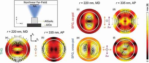
The theoretical calculations have also been performed to obtain the back-scattered nonlinear far-field emission in the form of back-focal-plane images. The results are shown in both for SFG and THG for two representative ND radii: 220 nm (MD) and 335 nm (AP). The magnitude of the Poynting vectors is shown in , where the experimental Numerical Aperture NA (equal to 0.85) is highlighted in white. The simulated back-focal plane images have the 2-fold rotational symmetry of either the illumination or the zincblende lattice seen along the [001] direction. These maps are also useful to qualitatively describe the behavior of the SFG measurements. In fact, the experimental SFG signals have similar amplitude around the MD resonances for the two different input pump polarizations, instead the SFG signal shows a maximum intensity peak and a subsequent dip around the AP for cross- or co-polarized beams, respectively. Similarly, the simulated maps show that the generated SFG is mostly confined inside the experimental NA (fixed to 0.85, white circle) for both incident polarizations around the MD resonance. In contrast, around the AP resonance the emitted SFG is mostly confined inside the NA for cross-polarized beams while is mainly radiated outside the NA when the pumps are co-polarized. This is in good agreement with the trends at the MD and AP resonances under co and cross-polarized excitations depicted in . Let us recall that the integrated intensity of the superposition of the SFG and THG fields, although emitted at the same wavelength, displays no interference because the SFG and THG emission always have opposite parity with respect to the coordinate axes.
Figure 6. Simulated back-focal-plane images. The top left panel reports a sketch of the nonlinear emission coming from the pillar which is calculated in the far-field approximation over a finite numerical aperture, NA. The bottom left panel reports the BFP related to the THG (a) at the magnetic dipole (MD) resonance and (b) at the anapole condition (AP). The white circle indicates a numerical aperture of 0.85, equal to the experimental one. The right panels are related to the SFG: (c) reports the BFP for co-polarized beams at the MD resonance while (d) the BFP at the AP condition. (e) and (f): same as (c), (d) but for the case of cross-polarized beams. The polarization of the pumps is indicated by the arrows in the middle of each image row. The black arrows indicate the electric fields ETHG and ESFG, respectively. The magnitude of the Poynting vectors STHG and SSFG is displayed in false colors.
As expected, the numerical calculations lead to more efficient generation of nonlinear signal in comparison to the experimental measurements. In any case the SFG-to-THG power ratio, which is more significant than the absolute value, have the same order of magnitude for both calculations and experiments. Specifically, the ratio is about 40 for the measurements and 20 in the calculations. Regarding the difference in the two ratios, let us clarify that the measured one is quite reliable within experimental uncertainties because the two nonlinear signals have exactly the same frequency and zero interferences. Conversely, the simulated ratio is strictly related to the input values of χ(2) and particularly of χ(3), which is affected by high uncertainty in the literature. Moreover, the initial value selected for χ(3) is related to a GaAs crystal, rather than to an AlGaAs crystal. To map the experimental ratio, the selected χ(3) value only needs to be reduced by a factor equal to 1.4, leading to a χ(3) value of 10−20 m2/V2 for Al0.18Ga0.82As. Of course, this evaluation is affected by large systematic errors and the resulting value of χ(3), therefore, should be considered as an order-of-magnitude estimation. Importantly, the obtained χ(3) for Al0.18Ga0.82As is in line with the estimated uncertainty for GaAs. At the same time, this procedure can be used to determine the nonlinear optical properties for other nonlinear materials and possibly with higher fidelity.
To summarize, in this section, efficient SFG is demonstrated for individual dielectric resonators made of AlGaAs. Moreover, due to the specific wavelength choice, the degenerate SFG and THG signals allow to foresee the ratio between χ(2) and χ(3) and, in this way, predict the χ(3) value of AlGaAs. Finally, the strong dependence of the nonlinear emission on the excitation properties, such as the pump polarizations, and on the geometrical parameters of the system makes dielectric nanocylinders promising building blocks of nonlinear metasurfaces.
IV. SFG in dielectric metasurfaces
In this section, we report the newest achievements related to SFG in dielectric metasurfaces. The fundamental study reported in the Section III represents the cardinal core for understanding the nonlinear SFG mechanism coming from a metasurface. Here, we will focus on a specific application: by optimizing a dielectric metasurface we present an approach to achieve IR up-conversion imaging [Citation95,Citation96]. Consider a metasurface, composed of nanocylinders fabricated on (110) GaAs wafers, excited by two laser beams, defined as the pump and the signal. In contrast to the previous section, now, the wavelengths are different for the two incident beams and are respectively equal to 860 nm for the pump and 1530 nm for the signal. The latter choice is dictated by applications in night-vision technologies where thermal vision devices amplify long-wave IR emitted by normal temperature objects, whereas the pump beam is fixed to 860 nm, since pulsed light sources are easily available around this wavelength. By exploiting SFG within the resonant metasurface, it is possible to generate an upconverted green light in the visible spectrum at a wavelength of 550 nm, thus where the human eye has maximum sensitivity. Let us recall that when facing the lattice effects of a metasurface, the nonlinear emission is shaped into different diffraction orders, depending on the periodicity of the metasurface. Thus, for practical applications, a crucial feature to obtain is the nonlinear emission redirected towards the zero-th diffraction order, facilitating its detection along the normal direction. Several nano-resonators geometries have been proposed in the literature to achieve this goal. All the designed solutions are based on the symmetry breaking of the problem either from structural, geometrical or excitation viewpoint [Citation76,Citation79]. In details, several approaches have been recently exploited to modify the spatial emission properties of the second-order harmonic generated light. One opportunity is given by tilting the fundamental pump with respect to the main crystal axis of the nanostructured antenna [Citation74]. A different possibility consists of creating a surrounding grating structure that allows the deviation of the harmonic radiation emitted at grazing angles from the optical resonators along its normal [Citation75]. The dielectric grating permits phase control of the nonlinear light produced by the nanoantennas and adjust the harmonic radiation for discretionary collection angles. It has also been presented an intuitive approach, established on symmetry breaking in the geometrical shape of AlGaAs cylindrical nanoresonators to obtain SHG towards the normal direction [Citation76]. The asymmetric fabricated structure is known as ‘nano-chair’ and represents a fundamental building block for tunable harmonic generation [Citation77,Citation83]. Finally, the fabrication of dielectric nanodisks with crystalline axis rotated with respect to the global coordinate system has been proved by facing epitaxial growth on either (110) or (111) substrates [Citation40,Citation97–99]. In this context, GaAs (110) nanoantennas could represent a valuable solution because, with this choice of crystalline orientation, GaAs nanoresonators have shown highly normal SHG emission. Thus, a GaAs (110) metasurface will allow two copropagating beams to generate SFG light, mainly emitted along the normal direction.
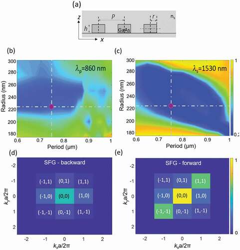
The optimized metasurface is constituted by GaAs nanocylinder with a radius of 225 nm, height of 400 nm and a period equal to 750 nm, see ). The choice of these parameters guarantees the spectral overlap of the involved wavelengths. In other words, the simultaneous excitations of resonances at 1530 nm, 860 nm and 550 nm, (not shown here) is fulfilled, as indicated by the 2D transmission maps of . The transmittance estimation have been performed in Comsol Multiphysics, as a function of the period and the pillar radius. The calculations are obtained by considering a unitary cell composed of a GaAs nanocylinder embedded within a homogenous surrounding material (with refractive index, ns, equal to 1.44) and by implementing Floquet boundary conditions at the cell borders to simulate an infinite periodic structure. The final design is highlighted by the purple points of ) and (c). Once the metasurface linear behavior is simulated, the nonlinear SFG calculations are performed, following the same steps and procedures as reported in Section III. The high efficiencies associated with the doubly resonant behavior in the linear regime enables the generation of an efficient SFG signal. The total forward SFG conversion efficiency, η = P SFG/P s is equal to 3 10−7 for Is = 1GW/cm2. Moreover, as previously anticipated, the (110) GaAs crystalline axis orientation allows to obtain a non-null emission normal to the metasurface, both in the backward and forward direction, as depicted in ) and (e) where the SFG diffraction order decomposition is displayed for the optimized metasurface. In particular, for the selected metasurface parameters shown in ) and (c), the SFG zero-th diffraction order is the most efficient, meaning that the generated SFG is mainly directed along the normal direction.
Figure 7. (a) Schematic transverse section of the designed metasurface indicating the height (h) and the GaAs pillar radius (r), together with the period (P). The pillar are assumed to be surrounded by a homogenous material with refractive index ns. (b,c) Calculated transmittance of the GaAs metasurface as a function of the pillar radius and period of the array for an incident wavelength of (b) 860 nm (pump) and (c) 1530 nm (signal). In all the calculations the nanoantenna height is fixed at 400 nm. A concomitant double-resonant behavior (either at the pump or at the signal wavelength) is achieved when the period is equal to 0.75 μm and the radius is 225 nm, as highlighted by the purple dots. (d,e) Corresponding far-field diffraction distribution of the SFG emitted from the optimized metasurface, when illuminated by the two incident beams, in the (d) backward and (e) forward direction. The zero-th diffraction order – (0, 0) – is the most efficient.
The fabricated samples are obtained through electron-beam lithography following the same procedure as reported in [Citation95]. The result of the fabrication is the metasurface shown in (a) & (b), which covers a total area of 30 30 μm. In this realization the GaAs cylindrical pillars are bonded to a thin glass substrate and embedded within a benzocyclobutene layer. The linear trasmission spectrum of the fabricated metasurface is measured by white light spectroscopy and compared with the numerical predictions, see . The overall agreement is good. The green vertical line indicates the spectral position of the SFG walength at 550 nm, the orange one the wavelength of the pump at 860 nm, while the red one indicates the wavelength of the signal at 1530 nm. We note that the calculations are obtained by considering the disperion of the surrounding benzocyclobutene layer.
Figure 8. (a,b) Scanning Electron Micrographs images of the fabricated nanoantennas (a) before and (b) after lift-off from the substrate. Experimental (c), (d) and corresponding (e), (f) calculated transmission spectra of the optimized GaAs metasurface in different spectral ranges. The left panel are for the visible region while the right one are for the infra-red region. The wavelength positions of the SFG, pump, and signal are indicated by the green, Orange, and red vertical lines, respectively. Adapted from [Citation95].
![Figure 8. (a,b) Scanning Electron Micrographs images of the fabricated nanoantennas (a) before and (b) after lift-off from the substrate. Experimental (c), (d) and corresponding (e), (f) calculated transmission spectra of the optimized GaAs metasurface in different spectral ranges. The left panel are for the visible region while the right one are for the infra-red region. The wavelength positions of the SFG, pump, and signal are indicated by the green, Orange, and red vertical lines, respectively. Adapted from [Citation95].](/cms/asset/b17745ed-0f7b-4b4b-975f-a2e12edd6e8b/tapx_a_2022992_f0008_oc.jpg)
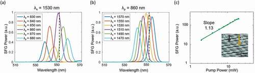
Concerning the nonlinear emission instead, the experimental characterization is performed by using an optical parametric oscillator (OPO) pumped by an 80 MHz repetition rate Ti:Sapphire laser, which allows delivering simoultaneusly on the fabricated sample two beams with mutually coherent pulse trains (i.e. a higher energy pump and a lower energy signal). Firstly, the wavelength of the signal is fixed to 1530 nm and the pump wavelength is varied between 830 nm and 880 nm, see ). As predicted by the simulation, the maximum SFG signal is obtained when the pump wavelength is around 860 nm. Secondly, the pump is fixed to 860 nm and the signal wavelength is tuned in the range of 1470–1570 nm, see ). The maximum SFG signal is obtained for a signal wavelength equal to 1530 nm, close to the value of 1550 nm predicted by the simulation. These experimental measurements demonstrate that the maximum nonlinear emission is obtained when the metasurface is resonant at all the wavelengths involved in the process. To prove the origin of the measured SFG at 550 nm, the average power of the pump beam is continuosly increased from 2 to 20 mW in steps of 2 mW, while maintaining the signal beam power constant. ) shows the measured instensity of the parametric emission plotted on a log-log scale. A linear dependence on the pump power with a slope of 1.13 is recorded, confirming the SFG nature of the measured emission. The maximum experimental SFG efficiency, which is smaller than the theoretical one due to fabrication imperfections, is η = 6 10−8 when using incident average powers equal to Pave_p = 16.4 mW and Pave_s = 16.8 mW.
Figure 9. Spectral dependence of the SFG emission on the varying wavelength of (a) the pump beam from 830 to 880 nm (by fixing the signal at 1530 nm), and (b) the signal beam from 1470 to 1570 nm (by keeping the pump at 860 nm). The black dashed lines indicate the maximum SFG obtained by the numerical simulations. (c) Intensity dependence of the SFG on the pump power in a log-log plot. The solid line represents the linear fit to the experimental data (slope equal to 1.13). The inset display a Scanning Electron Micrographs image of the metasurface under test. The grey and yellow arrows represent the signal and pump beams, respectively.
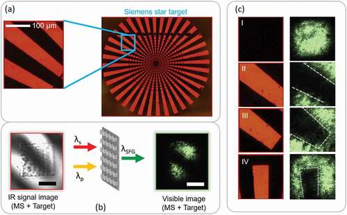
A thorough experimental analysis of the temporal synchronization between the pump and the signal is carried out by using a free-space variable delay line. The measured temporal duration of the SFG pulses is about 267 fs, which corresponds to the convolution of the pump and the signal pulses. This result indicates that the up-conversion process is mediated by a fast (electronic) nonlinearity and thus maintains the temporal information of the femtosecond IR pulses, therefore nonlinear metasurfaces can find applications in ultra-fast IR imaging. In particular, in the optimized GaAs metasurface, a practical example of up-conversion IR imaging can be realized, as shown in . In this scenario, the signal beam (at 1530 nm) passes through a target (Siemens star), that is imaged by a focusing lens onto the metasurface. In this way, the signal beam carries the IR information (i.e. an image). Concurrently, the pump beam at 860 nm is also focused onto the GaAs sample. Following the same nonlinear mechanism described before, at the metasurface, the IR image is converted, through the metasurface-mediated SFG process, to a visible one. Since the SFG is a coherent process, all the IR spatial information should be fully translated to the visible image, see (a) – (b). The main limiting conversion factor is related to having well-fabricated pillars forming the metasurface; any fabrication defects could introduce artifacts in the up-converted image in the visible. Please note that the IR image shown in ) is acquired with an InGaAs IR camera, using only the signal beam as the excitation source, while the visible images are captured using a conventional CCD camera. ) reports four acquired visible images in correspondence to different target positions – including the control case in which the target has been removed from the path of the signal beam.
Figure 10. (a) Optical microscope image of the Siemens star utilized for imaging. The section of the target used in the IR image is highlighted by the light-blue square. (b) The plot in the middle represents a sketch of the IR up-conversion imaging mechanism by exploiting the optimized GaAs metasurface: the metasurface is simultaneously illuminated by the pump and signal beams, generating at the output the SFG emission. The left panel shows the IR signal image acquired with an InGaAs camera. By simultaneously illuminating the metasurface with the IR image (in the signal beam) and the pump beam, due to the SFG process, a visible image of the target is obtained, which is subsequently imaged by a lens onto a CCD camera. The size of the fabricated metasurface is 30 μm×30 μm whereas the scale bars correspond to 15 μm. (c) Optical microscope images acquired at different positions of the target (left column) and their visible upconverted images (right column). The position (I) shows the SFG emission in the absence of the target whereas positions from (II) to (IV) display the visible SFG images for three different target positions in the transverse plane.
The low-noise visible images are obtained at room temperature, in great advantage compared to other technologies. Differently from common IR cameras, the proposed nano-platform is not affected by thermal noise. Still, the presented proof-of-principle design has lot of rooms for further optimized. For instance, the resonances can be selected to attain a higher field-enhancement leading to higher SFG conversion efficiency; the metasurface can be also optimized to operate in more than one single IR-channel, achieving thereby a multi-IR responsive device. To conclude, in this section we have presented a dielectric metasurface able to perform infrared up-conversion, at the nanoscale, through the SFG mechanism. An IR image is converted to visible wavelengths by mixing the 1530 nm signal beam with a pump beam at 860 nm within the metasurface, using the ultra-fast SFG nonlinear process. This achievement can facilitate the creation of innovative night vision tools and IR sensor devices.
V. Conclusions
The field of dielectric and semiconductor nanoresonators and metasurfaces with large bulk susceptibility, χ(2), and an associated enhanced nonlinear emission is rapidly developing inspired by basic demonstrations of SHG in high-refractive-index nanoparticles. Dielectric resonators offer peculiar properties such as high electromagnetic enhancement, strong nonlinear light–matter interaction, and low infrared losses that are especially advantageous for the design of nonlinear platforms. Among all the nonlinear phenomena of second order, the SFG is of particular interest. Indeed, by carefully designing dielectric nanostructures it is possible to obtain an efficient SFG signal that propagates in the normal direction to the substrate, which is desirable for many applications.
In this review, after presenting the main achievements regarding the SHG in dielectric devices, we discuss the most recent results obtained in terms of SFG from both isolated nano-structures and metasurfaces. Concerning the individual nanostructure, we report the fundamental study of SFG coming from AlGaAs pillars when the first incident pump has a frequency ω and the second one is at 2 ω. This allows obtaining a SFG emission with the same wavelength of the emitted THG signal. Hence, a strategy to compute the χ(3) value of AlGaAs is presented. The reported approach can also be easily exploited for other materials, obtaining a solid estimation of the nonlinear susceptibility of the third order in dielectrics which is commonly uncertain. Regarding the 2D arrangement of nanoresonators by exploiting the SFG mechanism, we present an IR imaging device using the SFG process in a GaAs metasurface. In particular, we show that an IR image, if properly mixed with a pump beam, can be translated to the visible spectral range. The presented results may open new possibilities for the realization of ultra-compact IR imaging platforms with possible applications in night vision instruments, machine vision and life sciences.
Disclosure statement
No potential conflict of interest was reported by the author(s).
Additional information
Funding
References
- Celebrano M, Wu X, Baselli M, et al. Mode matching in multiresonant plasmonic nanoantennas for enhanced second harmonic generation. Nat Nanotechnol. 2015;10:412–25.
- Kauranen M, Zayats AV. Nonlinear plasmonics. Nat Photonics. 2012;6:737–748.
- Kabashin AV, Evans P, Pastkovsky S, et al. Plasmonic nanorod metamaterials for biosensing. Nat Mater. 2009;8:867–871.
- Kuznetsov AI, Miroshnichenko AE, Brongersma ML, et al. Optically resonant dielectric nanostructures. Science. 2016;354. DOI:10.1126/science.aag2472
- Grinblat G. Nonlinear dielectric nanoantennas and metasurfaces: frequency conversion and wavefront control. ACS Photonics. 2021;8:3406–3432.
- Zheludev NI, Kivshar YS. From metamaterials to metadevices. Nat Mater. 2012;11:917–924.
- Decker M, Staude I, Falkner M, et al. High-efficiency dielectric huygens’ surfaces. Adv Opt Mater. 2015;3:813–820.
- Butet J, Brevet P-F, Martin OJ. Optical second harmonic generation in plasmonic nanostructures: from fundamental principles to advanced applications. ACS Nano. 2015;9:10545–10562.
- Zhang HC, Fan Y, Guo J, et al. Second-harmonic generation of spoof surface plasmon polaritons using nonlinear plasmonic metamaterials. ACS Photonics. 2015;3:139–146.
- Noor A, Damodaran AR, Lee I-H, et al. Mode-matching enhancement of second-harmonic generation with plasmonic nanopatch antennas. ACS Photonics. 2020;7:3333–3340.
- Thyagarajan K, Rivier S, Lovera A, et al. Enhanced second-harmonic generation from double resonant plasmonic antennae. Opt Express. 2012;20:12860–12865.
- Albella P, de La Osa RA, Moreno F, et al. Electric and magnetic field enhancement with ultralow heat radiation dielectric nanoantennas: considerations for surface-enhanced spectroscopies. ACS Photonics. 2014;1:524–529.
- Petosa A, Apisak I. Dielectric resoNATOr antennas: a historical review and the current state of the art. IEEE Antennas Propag Magazine. 2010;52:91–116.
- Bohren CF, Huffman DR. Absorption and scattering of light by small particles. Weinheim, Germany: John Wiley & Sons; 2008.
- Zhao Q, Zhou J, Zhang F, et al. Mie resonance-based dielectric metamaterials. Mater Today. 2009;12:60–69.
- Evlyukhin AB, Novikov SM, Zywietz U, et al. Demonstration of magnetic dipole resonances of dielectric nanospheres in the visible region. Nano Lett. 2012;12:3749–3755.
- Kuznetsov AI, Miroshnichenko AE, Fu YH, et al. Magnetic light. Sci Rep. 2012;2:1–6.
- Fu YH, Kuznetsov AI, Miroshnichenko AE, et al. Directional visible light scattering by silicon nanoparticles. Nat Commun. 2013;4:1–6.
- Person S, Jain M, Lapin Z, et al. Demonstration of zero optical backscattering from single nanoparticles. Nano Lett. 2013;13:1806–1809.
- Krasnok AE, Simovski CR, Belov PA, et al. Superdirective dielectric nanoantennas. Nanoscale. 2014;6:7354–7361.
- Krasnok AE, Miroshnichenko AE, Belov PA, et al. All-dielectric optical nanoantennas. Opt Express. 2012;20:20599–20604.
- Liu S, Sinclair MB, Saravi S, et al. Resonantly enhanced second-harmonic generation using III–V semiconductor all-dielectric metasurfaces. Nano Lett. 2016;16:5426–5432.
- Liu S, Vabishchevich PP, Vaskin A, et al. An all-dielectric metasurface as a broadband optical frequency mixer. Nat Commun. 2018;9:1–6.
- Vabishchevich PP, Liu S, Sinclair MB, et al. Enhanced second-harmonic generation using broken symmetry III–V semiconductor fano metasurfaces. ACS Photonics. 2018;5:1685–1690.
- Kruk S, Weismann M, Bykov AY, et al. Enhanced magnetic second-harmonic generation from resonant metasurfaces. ACS Photonics. 2015;2:1007–1012.
- Marino G, Rocco D, Gigli C, et al. Harmonic generation with multi-layer dielectric metasurfaces. Nanophotonics. 2021;10:1837–1843.
- Fedotova A, Younesi M, Sautter J, et al. Second-Harmonic Generation in resonant nonlinear metasurface based on lithium niobate. Nano Lett. 2020;20:8608–8614.
- Löchner FJ, Fedotova AN, Liu S, et al. Polarization-dependent second harmonic diffraction from resonant GaAs metasurfaces. ACS Photonics. 2018;5:1786–1793.
- Tong W, Gong C, Liu X, et al. Enhanced third harmonic generation in a silicon metasurface using trapped mode. Opt Express. 2016;24:19661–19670.
- Frizyuk K, Volkovskaya I, Smirnova D, et al. Second-harmonic generation in Mie-resonant dielectric nanoparticles made of noncentrosymmetric materials. Phys Rev B. 2019;99:075425.
- Shcherbakov MR, Neshev DN, Hopkins B, et al. Enhanced third-harmonic generation in silicon nanoparticles. Nano Lett. 2014;14:6488–6492.
- Wang L, Kruk S, Xu L, et al. Shaping the third-harmonic radiation from silicon nanodimers. Nanoscale. 2017;9:2201–2206.
- Melik-Gaykazyan E, Kruk SS, Camacho-Morales R, et al. Selective third-harmonic generation by structured light in mie-resonant nanoparticles. ACS Photonics. 2018;5:728–733.
- Kroychuk MK, Shorokhov AS, Yagudin DF, et al. Enhanced nonlinear light generation in oligomers of silicon nanoparticles under vector beam illumination. Nano Lett. 2020;20:3471–3477.
- Smirnova D, Kruk S, Leykam D, et al. Third-harmonic generation in photonic topological metasurfaces. Phys Rev Lett. 2019;123:103901.
- Rahmani M, Leo G, Brener I, et al. Nonlinear frequency conversion in optical nanoantennas and metasurfaces: materials evolution and fabrication. Opto-Electronic Advances. 2018;1:180021.
- Boyd RW. Nonlinear optics. United States: Academic Press; 2020.
- Anthur AP, Zhang H, Paniagua-Dominguez R, et al. Continuous wave second harmonic generation enabled by quasi-bound-states in the continuum on gallium phosphide metasurfaces. Nano Lett. 2020;20:8745–8751.
- Sanatinia R, Anand S, Swillo M. Modal engineering of second-harmonic generation in single GaP nanopillars. Nano Lett. 2014;14:5376–5381.
- Sautter JD, Xu L, Miroshnichenko AE, et al. Tailoring second-harmonic emission from (111)-GaAs nanoantennas. Nano Lett. 2019;19:3905–3911.
- Carletti L, Zilli A, Moia F, et al. Steering and encoding the polarization of the second harmonic in the visible with a monolithic LiNbO3 metasurface. ACS Photonics. 2021;8:731–737.
- Huang Z, Lu H, Xiong H, et al. Fano resonance on nanostructured lithium niobate for highly efficient and tunable second harmonic generation. Nanomaterials. 2019;9:69.
- De Ceglia D, Carletti L, Vincenti MA, et al. Second-harmonic generation in mie-resonant GaAs nanowires. Appl Sci. 2019;9:3381.
- Barreda A, Saiz J, Gonzalez F, et al. Recent advances in high refractive index dielectric nanoantennas: basics and applications. AIP Adv. 2019;9:040701.
- Wolf O, Campione S, Yang Y, et al. Multipolar second harmonic generation in a symmetric nonlinear metamaterial. Sci Rep. 2017;7:1–7.
- Kang L, Bao H, Werner DH. Efficient second-harmonic generation in high Q-factor asymmetric lithium niobate metasurfaces. Opt Lett. 2021;46:633–636.
- Aitchison JS, Hutchings D, Kang J, et al. he nonlinear optical properties of AlGaAs at the half band gap. IEEE J Quantum Electron. 1997;33:341–348.
- Gigli C, Marino G, Borne A, et al. ll-dielectric nanoresoNATOrs for X(2) nonlinear optics. Front Phys. 2019;7:221.
- Carletti L, Locatelli A, Stepanenko O, et al. Enhanced second-harmonic generation from magnetic resonance in AlGaAs nanoantennas. Opt Express. 2015;23:26544–26550.
- Gili VF, Carletti L, Locatelli A, et al. Monolithic AlGaAs second-harmonic nanoantennas. Opt Express. 2016;24:15965–15971.
- Rocco D, Vincenti MA, De Angelis C. Boosting second harmonic radiation from AlGaAs nanoantennas with epsilon-near-zero materials. Appl Sci. 2018;8:2212.
- Rocco D, De Angelis C, De Ceglia D, et al. Dielectric nanoantennas on epsilon-near-zero substrates: impact of losses on second order nonlinear processes. Opt Commun. 2020;456:124570.
- Rocco D, Gili VF, Ghirardini L, et al. Tuning the second-harmonic generation in AlGaAs nanodimers via non-radiative state optimization. Photonics Res. 2018;6:B6–B12.
- Carletti L, Koshelev K, De Angelis C, et al. Giant nonlinear response at the nanoscale driven by bound states in the continuum. Phys Rev Lett. 2018;121:033903.
- Gili VF, Ghirardini L, Rocco D, et al. Metal–dielectric hybrid nanoantennas for efficient frequency conversion at the anapole mode. Beilstein J Nanotechnol. 2018;9:2306–2314.
- Han Z, Ding F, Cai Y, et al. Significantly enhanced second-harmonic generations with all-dielectric antenna array working in the quasi-bound states in the continuum and excited by linearly polarized plane waves. Nanophotonics. 2021;10:1189–1196.
- Jiang H, Cai Y, Han Z. Strong second-harmonic generation in dielectric optical nanoantennas resulting from the hybridization of magnetic dipoles and lattice resonances. JOSA B. 2020;37:3146–3151.
- Carletti L, Kruk SS, Bogdanov AA, et al. High-harmonic generation at the nanoscale boosted by bound states in the continuum. Phys Rev Res. 2019;1:023016.
- Li Y, Huang Z, Sui Z, et al. Optical anapole mode in nanostructured lithium niobate for enhancing second harmonic generation. Nanophotonics. 2020;9:3575–3585.
- Volkovskaya I, Xu L, Huang L, et al. Multipolar second-harmonic generation from high-Qquasi-BIC states in subwavelength resonators. Nanophotonics. 2020;9:3953–3963.
- Koshelev K, Bogdanov A, Kivshar Y. Meta-optics and bound states in the continuum. Sci Bull. 2019;64:836–842.
- Melik-Gaykazyan E, Koshelev K, Choi J-H, et al. From Fano to Quasi-BIC resonances in individual dielectric nanoantennas. Nano Lett. 2021;21:1765–1771.
- Miroshnichenko A, Evlyukhin A, Yu Y, et al. Nonradiating anapole modes in dielectric nanoparticles. Nat Commun. 2015;6:1–8.
- Fonda L. Bound states embedded in the continuum and the formal theory of scattering. Ann Phys. 1963;22:123–132.
- Stillinger F, Herrick D. Bound-states in continuum. Phys Rev A. 1975;11:446–454.
- Friedrich H, Wintgen D. Interfering resonances and bound states in the continuum. Phys Rev A. 1985;32:3231–3242.
- Hsu C, Zhen B, Stone AD, et al. Bound states in the continuum. Nat Rev Mater. 2016;1:1–13.
- Paddon P, Young J. Two-dimensional vector-coupled-mode theory for textured planar waveguides. Phys Rev B. 2000;61:2090–2101.
- Bulgakov E, Sadreev A. Robust bound state in the continuum in a nonlinear microcavity embedded in a photonic crystal waveguide. Opt Lett. 2014;39:5212–5215.
- Sadrieva Z, Belyakov M, Balezin M, et al. Experimental observation of a symmetry-protected bound state in the continuum in a chain of dielectric disks. Phys Rev A. 2019;99:053804.
- Marinica D, Borisov A, Shabanov S. Bound states in the continuum in photonics. Phys Rev Lett. 2008;100:183902.
- Bulgakov E, Pichugin K, Sadreev A. All-optical light storage in bound states in the continuum and release by demand. Opt Express. 2015;23:22520–22531.
- Gandolfi M, Tognazzi A, Rocco D, et al. Near-unity third-harmonic circular dichroism driven by a quasibound state in the continuum in asymmetric silicon metasurfaces. Phys Rev A. 2021;104:023524.
- Carletti L, Marino G, Ghirardini L, et al. Nonlinear goniometry by second-harmonic generation in AlGaAs nanoantennas. ACS Photonics. 2018;5:4386–4392.
- Ghirardini L, Marino G, Gili VF, et al. Shaping the nonlinear emission pattern of a dielectric nanoantenna by integrated holographic gratings. Nano Lett. 2018;18:6750–6755.
- Rocco D, Gigli C, Carletti L, et al. Vertical second harmonic generation in asymmetric dielectric nanoantennas. IEEE Photonics J. 2020;12:1–7.
- Gigli C, Marino G, Artioli A, et al. Tensorial phase control in nonlinear meta-optics. Optica. 2021;8:269–276.
- Xu L, Rahmani M, Smirnova D, et al. Highly-efficient longitudinal second-harmonic generation from doubly-resonant AlGaAs nanoantennas. Photonics. 2018;5:29.
- Carletti L, Rocco D, Locatelli A, et al. Controlling second-harmonic generation at the nanoscale with monolithic AlGaAs-on-AlOx antennas. Nanotechnology. 2017;28:114005.
- Frizyuk K. Second-harmonic generation in dielectric nanoparticles with different symmetries. JOSA B. 2019;36:F32–F37.
- Rocco D, Carletti L, Caputo R, et al. Switching the second harmonic generation by a dielectric metasurface via tunable liquid crystal. Opt Express. 2020;28:12037–12046.
- Celebrano M, Rocco D, Gandolfi M, et al. Optical tuning of dielectric nanoantennas for thermo-optically reconfigurable nonlinear metasurfaces. Opt Lett. 2021;46:2453–2456.
- Rocco D, Gandolfi M, Tognazzi A, et al. Opto-thermally controlled beam steering in nonlinear all-dielectric metastructures. Opt Express. 2021;29:37128–37139.
- Tognazzi A, Locatelli A, Vincenti M, et al. Tunable optical antennas using vanadium dioxide metal-insulator phase transitions. Plasmonics. 2019;14:1283–1288.
- Cao T, Liu K, Tang Y, et al. A high-index Ge2Sb2Te5-based fabry–perot cavity and its application for third-harmonic generation. Laser Photonics Rev. 2019;13:1900063.
- Carletti L, de Ceglia D, Vincenti M, et al. Self-tuning of second-harmonic generation in GaAs nanowires enabled by nonlinear absorption. Opt Express. 2019;27:32480–32489.
- Guo X, Ding Y, Ni X. Electrically tunable second harmonic generation enhancement on a parametrically excited metasurface, FTh1C.3 CLEO: QELS_Fundamental Science, 2020.
- Schirato A, Mazzanti A, Proietti Zaccaria R, et al. All-optically reconfigurable plasmonic metagrating for ultrafast diffraction management. Nano Lett. 2021;21:1345–1351.
- Pogna EAA, Celebrano M, Mazzanti A, et al. Ultrafast, all optically reconfigurable, nonlinear nanoantenna. ACS Nano. 2021;15:11150–11157.
- Carletti L, Gandolfi M, Rocco D, et al. Reconfigurable nonlinear response of dielectric and semiconductor metasurfaces. Nanophotonics. 2021;10:4209–4221.
- Sain B, Meier C, Zentgraf T. Nonlinear optics in all-dielectric nanoantennas and metasurfaces: a review. Advanced Photonics. 2019;1:024002.
- Li G, Zhang S, Zentgraf T. Nonlinear photonic metasurfaces. Nat Rev Mater. 2017;2:1–14.
- Zilli A, Rocco D, Finazzi M, et al. Frequency tripling via sum-frequency generation at the nanoscale. ACS Photonics. 2021;8:1175–1182.
- Vincenti M, De Ceglia D, Roppo V, et al. Harmonic generation in metallic, GaAs-filled nanocavities in the enhanced transmission regime at visible and UV wavelengths. Opt Express. 2011;19:2064–2078.
- Camacho-Morales R, Dreischuh A, Xu L, et al. Infrared upconversion imaging in nonlinear metasurfaces. Advanced Photonics. 2021;3:036002.
- Morales MC, Rocco D, Xu L, et al. Infrared imaging in nonlinear GaAs metasurfaces. SPIE Micro+ Nano Materials, Devices, and Applications. 2019;11201:112011S.
- Xu L, Saerens G, Timofeeva M, et al. Forward and backward switching of nonlinear unidirectional emission from GaAs nanoantennas. ACS Nano. 2020;14:1379–1389.
- Chen S, Rahmani M, Li KF, et al. Third harmonic generation enhanced by multipolar interference in complementary silicon metasurfaces. ACS Photonics. 2018;5:1671–1675.
- Xu L, Rahmani M, Kamali KZ, et al. Boosting third-harmonic generation by a mirror-enhanced anapole resoNATOr. Light: Science and Applications. 2018;7:1–8.