
Abstract
Small unmanned aircraft systems (sUAS) offer key benefits over manned aircraft and satellite platforms used for remote sensing research, such as high spatial resolution, portability, simplicity of implementing ground control, affordability, and lack of reliance upon third-party imagery providers. Mountainous areas, which we define as locations that are higher than 2500 m in elevation and that contain slopes greater than 25°, pose a number of challenges to sUAS mapping operations that other environments do not, including reduced aircraft performance, cold temperatures, high winds, and limited accessibility. The purpose of our paper is to identify these challenges and discuss workflows used to mitigate these difficulties to achieve greater logistical and operational efficiency. We used a DJI Inspire 2 multirotor aircraft to conduct mapping missions in remote, mountainous areas to support subalpine forest inventory and assessment in Nevada and southern Utah. We identified several potential obstacles to collecting high-quality aerial image data in environments with high topographic variability and landscape heterogeneity. We found that sUAS are very useful and practical when performing mapping missions in these circumstances when operators account for potential environmental limitations (e.g., poor weather, shortened flight times due to atmospheric conditions, line-of-sight challenges, difficulty implementing ground control across steep sites, ensuring applicable aviation regulations are observed) and technological capabilities (terrain following, flight duration, etc.). This work has implications for a wide variety of scientific and management disciplines that involve low-altitude remote sensing research in mountainous areas.
Introduction
Small unmanned aircraft systems (hereafter abbreviated sUAS), defined in the United States as unmanned aircraft weighing less than 55 lbs. (14 C.F.R. Part 107 Citation2016), have become ubiquitous in their use in several disciplines in recent years. Perhaps the most widespread use of sUAS currently is as a remote sensing platform. sUAS are often equipped with high-resolution RGB, multispectral, and thermal infrared sensor packages. Their relatively low cost (compared to manned aircraft and satellite remote sensing platforms) and rapid deployment capabilities are ideal for low-altitude scientific imaging applications. Two basic types of sUAS are available – fixed-wing and multirotor systems. Off-the-shelf fixed-wing sUAS are suitable for surveying larger areas at relatively higher altitudes above ground level (AGL) (e.g., 160 hectares in 45 minutes at 122-m AGL), while multirotor sUAS are by their nature generally less efficient and can cover smaller areas on a single flight (e.g., 40 hectares in 25 minutes at 122-m AGL). However, multirotor systems have other advantages, including their ability to stop and hover, fly slowly, and easily descend to a lower altitude for more detailed imaging of a small area of interest. Additionally, multirotor systems, e.g., the DJI Inspire 2 (Dà-Jiāng Innovations, Shenzhen, China), tend to cost less than fixed-wing systems with similar capabilities.
sUAS have been used as remote sensing platforms to support a wide variety of applications, such as emergency management, agronomy, cadastral mapping, and infrastructure inspection (Silvagni et al. Citation2017; Khot et al. Citation2016; Shi et al. Citation2016; Crommelinck et al. Citation2016). Use cases are also numerous in environmental disciplines, including forestry, range management, wildlife management, geology, and oceanography (Linchant et al. Citation2015; Tang and Shao Citation2015; Laliberte, Winters, and Rango Citation2011; Eisenbeiss Citation2009). Relatively few academic papers have been published about conducting UAS-based remote sensing missions in mountainous locations, which are common settings for environmental research in many regions of the world. Still fewer detail challenges encountered best practices for flight operations. Ambrosia et al. (Citation2011) described missions conducted using a NASA-modified MQ-9 Predator B, dubbed Ikhana, for wildfire observation and firefighting coordination in several mountainous areas across the western United States. This large fixed-wing aircraft has a 400-lb sensor payload capacity and can fly up to 13,700 m in altitude for durations approaching 24 hours. The Ikhana flies well above the tops of mountains and is more suited to providing situational awareness rather than high-resolution mapping capabilities. Ragg and Fey (Citation2013) used two small UAS – a fixed-wing QUEST-UAV and a TWINS-NRN multicopter – outfitted with an RGB sensor to monitor an active rock slide at 2,900 m in the Austrian Alps. They described several challenges operating sUAS in this setting, including thin air, cold temperatures, strong and unpredictable winds, poor GNSS reception, and large differences in scale caused by steep slopes. Mirijovsky and Langhammer (Citation2015) studied the morphodynamics of a montane stream system in the Czech Republic using a Canon DSLR camera mounted aboard a Mikrokopter Hexa XL multirotor system (MikroKopter, Moormerland, Germany). They were able to create a multitemporal digital elevation model (DEM) dataset using structure-from-motion photogrammetry, from which they measured bank erosion rates. Gruen, Zhang, and Eisenbeiss (Citation2012) discuss a workflow for sUAS-based 3D modeling of an archeological site at 2930-m elevation in Bhutan. Their article focuses primarily on their process for processing the data and does not provide much detail on sUAS mapping procedures.
Mapping snow and ice cover are common applications for sUAS in high-altitude sites. Syromyatina et al. (Citation2015) performed mapping flights with a Geoscan 101 fixed-wing UAS (Geoscan Group, St. Petersburg, Russia) over two glaciers at altitudes ranging from 3400–3900-m above mean sea level (MSL) in the Tavan Bogd Mountains in Mongolia. De Michele et al. (Citation2016) used a SenseFly Swinglet-CAM fixed-wing UAS (senseFly, Cheseaux-sur-Lausanne, Switzerland) to characterize snow depths in an alpine location in northern Italy using multitemporal RGB imaging. Buhler et al. (Citation2017) detailed methods for reconstructing three-dimensional depictions of homogeneous snow surfaces following avalanches. They provided a useful perspective on the challenges of flying in a subalpine location (their study sites were in Switzerland and Austria), such as steep slopes, high elevation differences, and unfavorable atmospheric considerations, including low temperatures and high winds that exceeded the recommended limits for the Falcon 8 multirotor UAS (Intel, Santa Clara, California, USA) they used.
The purpose of this paper is to discuss how multirotor sUAS can be effectively used to conduct remote sensing missions in mountainous areas to support environmental research. Our objectives are to present techniques for operating sUAS in challenging operational environments in mountainous areas, to explain how to overcome difficulties related to the operational environment, and to develop a set of best practices for operating sUAS within these conditions. Additionally, we describe our methods and the best practices for collecting high-quality aerial image data in mountainous areas, which we define as locations where steep slopes (> 25°) and high elevations (> 2500-m MSL) create logistical challenges for sUAS-based mapping – challenges that are not present at study sites in low-elevation and topographically flat locations. These challenges include reduced thrust and shorter flight times due to reduced air pressure, cold temperatures, strong winds, problems with variable scale and resolution when mapping areas with steep slopes or significant topographic relief, difficulty maintaining visual line-of-sight (VLOS) with the UAS, and following current regulations from the Federal Aviation Administration (FAA) governing sUAS flights in the United States (14 C.F.R. Part 107 Citation2016). Our team successfully conducted mapping missions with sUAS at study sites in mountainous areas 17 times during 2017–2018, gaining valuable experience that has helped us develop specialized standard procedures for aerial imaging flights in locations with rugged terrain at high elevations.
Materials and methods
Data collection for this project was accomplished as part of a larger study to map subalpine forest stands in the Great Basin and Colorado Plateau ecoregions at a fine spatial scale. Study sites were selected based upon their forest species composition, accessibility, and topography. In total, seven sites in Utah and Nevada, U.S.A., were mapped using an sUAS during this project (; ).
Figure 1. Locations of the seven subalpine forest sites mapped using sUAS within the Great Basin and Colorado Plateau ecoregions. Map data courtesy of Esri, Garmin, USGS, NOAA, and NPS.
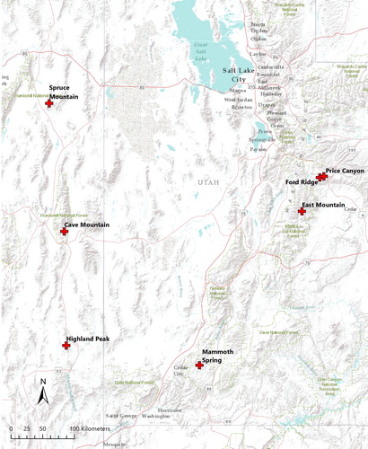
Table 1. Characteristics of the seven subalpine forest sites mapped during this project. Terrain data derived from USGS 3DEP.
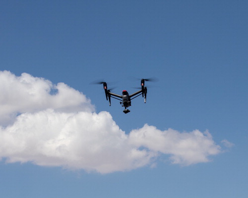
To accomplish the mapping missions, we selected a DJI Inspire 2 sUAS platform (). The Inspire 2 is a quadcopter designed for aerial photography and videography applications. One benefit of the Inspire 2 is its compatibility with various gimbaled cameras manufactured by DJI. We selected the DJI Zenmuse X4S camera system with integrated gimbal, which includes a 1-inch size RGB sensor with a fixed 94-degree field-of-view lens. An additional feature of the Inspire 2 is its ability to raise its landing legs after takeoff, providing the camera with an unobstructed 360-degree rotation capability while in flight. During some missions in which detailed spectral data were required, we used a Micasense Rededge-M multispectral camera (Micasense Inc., Seattle, Washington, U.S.A.). The Rededge-M is a small five-band multispectral imager designed for use aboard sUAS. It offers discrete bands centered at 475 nm (blue), 560 nm (green), 668 nm (red), 840 nm (near-infrared), and 717 nm (red-edge), offering the capabilities to produce natural color and color-infrared imagery, along with various vegetation indices that make use of the near-infrared and red-edge bands in tandem with a visible band (typically red).
Figure 2. DJI Inspire 2 with DJI Zenmuse X4S camera in operation at Highland Peak, Nevada.
The Inspire 2 is controlled via the DJI Cendence transmitter in tandem with an Apple iPad Pro (Apple Inc., Cupertino, California, U.S.A.) that functions as a computer ground control station. DJI’s Go 4 iOS app provides a live view of the video feed from the Inspire 2’s camera, along with real-time telemetry information such as GPS position, battery status, altitude, distance, and camera settings. The DJI software developer’s kit (SDK) enables third-party developers to create applications that leverage the functionality of the sUAS and the ground station software to offer enhanced capabilities, such as aerial mapping. After evaluating several iOS applications designed for mapping with DJI UAS, our team selected the Maps Made Easy Map Pilot for DJI app (www.mapsmadeeasy.com). This application has several useful features, including a terrain-following mode, a live map view that showed image footprints during each flight, and the ability to pre-cache basemap imagery in remote locations without reliable cellular data service. The application was programed to capture images at 75 percent overlap in both the forward and side directions, from an altitude of 121-m AGL. The camera exposure settings were automatically selected by the app, while white balance was manually set to the “Sunny” option during each flight to avoid issues with white balance variations associated with the use of the automatic white balance setting. Images were captured in the JPEG file format.
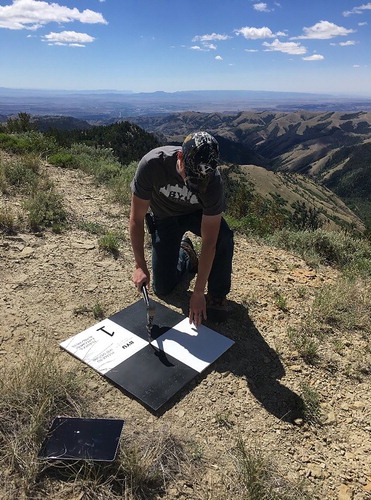
To improve the georectification accuracy of orthoimagery and photogrammetric point cloud models produced from these missions, we needed to establish absolute ground control within the areas we mapped (Mirijovsky and Langhammer Citation2015; Pix4D 2019). We created 24 ground control point (GCP) panels made from plywood boards cut to 0.6 m × 0.6 m dimensions. These square panels were painted with a checkerboard pattern to improve their visibility from the air, and to create obvious and well-defined center points that would serve as the actual GCP locations (). These GCPs were laid out at each site in a uniform pattern prior to conducting sUAS mapping flights. Distances between GCPs depended upon the total area of each site. The primary goal in GCP placement was to focus on the corners and edges of each site, and then to place several GCPs in a uniform pattern between the edges and corners of the area of interest. After placement, a Trimble GeoExplorer 6000 GNSS (Trimble Inc., Sunnyvale, California, U.S.A.) was used to collect differential precision global positioning system (GPS) data (latitude, longitude, and elevation) at each GCP location.
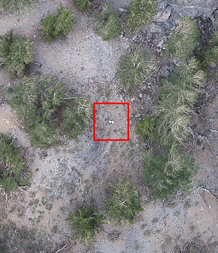
Figure 3. (a) Staking a ground control point (GCP) target at Ford Ridge, Utah. GCP boards are made of 0.6 m × 0.6 m plywood painted to be highly visible from the air. (b) An RGB aerial image of a GCP target in position at Spruce Mountain, Nevada (captured from 122-m AGL).
Following data acquisition, our team used Pix4Dmapper software (Pix4D SA, Lausanne, Switzerland) to post-process the imagery gathered on each mission. Pix4Dmapper is a photogrammetric mapping software package that uses structure-from-motion algorithms to produce orthomosaics, point clouds, and digital surface models (DSMs) from aerial imagery collected with a high percentage of overlap between adjacent images (Pix4Dmapper User Manual v4.0 2019; Westoby, Hambrey, and Glasser 2012). Following processing with Pix4D, the data products were imported into GIS software (e.g., ArcGIS) for further processing and information extraction.
Results and discussion
Benefits, drawbacks, and logistics of sUAS-based imaging in mountainous areas
UAS offer several key advantages over manned aircraft and satellite platforms when imaging in mountainous areas. First, UAS can fly close to the ground and collect ultra-high-resolution data in locations where manned aircraft would not be able to fly safely due to the danger of colliding with terrain or other terrestrial features (Laliberte, Winters, and Rango Citation2011). Second, sUAS can be easily transported in a four-wheel drive vehicle, or even carried by a person to a study site in a backpack, simplifying access to remote locations in many cases. Since the crew is positioned in the same general location as the UAS, ground control targets can be easily laid out over the study site prior to a mapping mission.
A key disadvantage of sUAS compared to higher-altitude platforms is their inability to provide mapping coverage over large geographic areas. The maximum acreage we could cover in a single 15–20-m mapping flight at 122-m AGL with the Inspire 2 was typically around 32 hectares. Because of this coverage area limitation, multirotor sUAS similar to the Inspire 2 are best suited for mapping small research plots with areas up to 40 hectares. Fixed-wing sUAS offer greater endurance than multirotor systems, but our team opted for a multirotor for reasons that will be discussed below.
A logistical aspect of operating sUAS is adhering to the regulatory structure that governs their operation for commercial purposes (14 CFR Part 107 – hereafter “Part 107”). Two key provisions of Part 107 are the altitude and distance restrictions on sUAS flights: sUAS are limited to operating up to 400 feet (122 meters) AGL and within VLOS of the remote pilot-in-command (RPIC) (14 C.F.R. Part 107 Citation2016). These two restrictions can be waived by the FAA under certain circumstances if an acceptable safety case is made. Many mapping missions would benefit from operating a UAS above 122 m and beyond VLOS distances to increase the aircraft’s ability to image larger areas per flight, albeit at a coarser spatial resolution. Another requirement of Part 107 is that RPIC candidates must obtain a remote pilot certificate (RPC) with an sUAS rating from the Federal Aviation Administration (FAA) to conduct or supervise sUAS operations for commercial purposes (14 C.F.R. Part 107 Citation2016). This certification requires the candidate to pass a written examination that tests their knowledge of weather, airspace, and operating limitations for sUAS. Then, after initial certification, remote pilots must pass a recertification test every 24 calendar months. This examination system has proved burdensome for some remote sensing scientists because of the need to learn seemingly complex aviation regulations, procedures, and jargon that are foreign to their area of specialization. Notwithstanding, the regulations in Part 107 represent significant progress toward standardizing sUAS flights in the United States (see Hardin et al. Citation2018, 9–11).
Platform selection – fixed wing versus multirotor
We decided early in the planning process for this project to utilize a multirotor sUAS instead of a fixed-wing system. Multirotors have the disadvantages of reduced aerodynamic and power efficiency (due to the energy spent by the motors creating lift for hovering and maneuvering), and generally shorter endurance. Their advantages lie in their ability to stop and hover, maneuver slowly around steep slopes and obstacles, and take off and land without a large area nearby to serve as a runway (∼75–100-m minimum distance for most fixed-wing aircraft) (Ragg and Fey Citation2013). Few or none of the sites we mapped had sufficient open space for fixed-wing takeoff and landing operations. Moreover, DJI multicopters (DJI does not offer fixed-wing UAS models) have a sophisticated SDK that allows third-party developers to write sophisticated mapping applications for DJI aircraft that control the functions of the onboard camera and provide navigation over the area of interest. There are several of these apps available for the iOS and Android platforms, including DroneDeploy, Pix4Dcapture, and the Map Pilot for DJI app that we selected (described above).
Besides maneuverability, another advantage of multirotor systems (including DJI products) is low cost. The system we acquired, the DJI Inspire 2, costs ∼$3600 for the airframe and gimballed Zenmuse X4S RGB camera. We also purchased additional batteries (six pairs total) for extended operational capabilities in remote areas, a rapid charging station, a GoProfessional hard case (GPC Custom Cases Inc., San Diego, California, U.S.A.) for transporting the Inspire 2 to study sites, a DJI Cendence transmitter (an upgrade from the stock transmitter), and an Apple iPad Pro to serve as the ground control station. The total investment for the Inspire 2 with accessories was around $7500. The un-gimballed Micasense Rededge-M multispectral camera could be optionally mounted to the Inspire 2 camera port using a custom 3D-printed adapter we designed. Total costs for the Rededge-M were approximately $5000. Off-the-shelf fixed-wing platforms that were comparable in their mapping capabilities were much more expensive. For example, the Sensefly eBee Classic (Sensefly, Cheseaux-sur-Lausanne, Switzerland) fixed-wing platform with RGB and multispectral sensor capabilities costs around $25,000, about twice the price of the Inspire 2 system with the Micasense Rededge-M camera. The primary benefit of the eBee over the Inspire 2 is its 50-min maximum endurance, which we did not consider to be worth the additional cost to our project. Furthermore, we were concerned that a fixed-wing sUAS would not be able to fly slowly enough or be sufficiently maneuverable to handle the complex terrain present in the mountainous environments where we operated.
Challenges of operating sUAS in mountainous areas
sUAS, and aircraft in general, perform less efficiently at high elevation than they do at altitudes near sea level. Lower air density in high-altitude locations means wings and rotors produce less lift and propellers produce less thrust than they would achieve at sea level. The reduced efficiency results in diminished aircraft endurance, or flight time, which limits the total area that can be mapped on a single flight (Ragg and Fey Citation2013). The term “density altitude,” defined as DJI, addresses the problem of reduced thrust at higher altitudes by selling high-altitude propellers for the Inspire 2 that have a greater pitch than the standard propellers, thereby producing more thrust in thinner air. Additionally, wind velocity tends to have greater potential at high altitudes and can be a factor in reducing aircraft endurance when flying upwind legs during a mapping mission. Finally, cold ambient air temperatures reduce the efficiency of the Inspire 2’s lithium polymer (LiPo) batteries, creating an additional variable that can have an impact on flight endurance (Ragg and Fey Citation2013). We learned that we needed to carefully evaluate weather forecasts prior to departure to our field sites, paying special attention to the temperature and wind velocity forecasts. Our Inspire 2 achieved flight times ranging from ∼15–20 minutes, depending upon flight elevation, wind speed, and ambient air temperature. Cold temperatures can also have a negative impact on crew comfort and performance during mapping flights. Due to the reduced flight times we experienced due to the aforementioned phenomena inherent to high mountainous areas, we invested in a total of six sets of flight batteries and a rapid charging station (powered via wall outlet or generator) to enable us to quickly land and swap batteries during aerial mapping missions that could not be completed on a single flight.
Line-of-sight problems are also common in mountainous areas. Per Part 107, the RPIC must maintain VLOS with the aircraft at all times during the flight operation (14 C.F.R. Part 107 Citation2016). Additionally, the aircraft uses a line-of-sight 2.4-GHz radio control link that must be maintained during flight. If the aircraft descends over a ridge away from the pilot’s location, the radio control link is lost. Although the flight software typically uploads all mission waypoints to the aircraft before flight and the aircraft continues to fly normally when radio signals are lost, the RPIC must still maintain VLOS with the aircraft (14 C.F.R. Part 107 Citation2016). Addressing radio- and visual line-of-sight challenges should be done during the preflight safety briefing. When possible, the UAS pilot should be pre-positioned on an elevated location within the study site to minimize the chance of losing both radio- and visual line-of-sight with the aircraft while in flight. During at least two of our mapping missions, the RPIC was forced to abort the automated mapping mission in order to avoid losing line-of-sight with the aircraft. As a last resort, we configured our Inspire 2 to use its “smart return-to-home” capabilities. In this mode, if the transmission signal is lost, the aircraft will return to its takeoff location using its built-in obstacle avoidance sensors to navigate over trees and slopes. An additional option for reducing the chances of losing VLOS is to use a designated visual observer (VO), who can aid the RPIC in maintaining VLOS (14 C.F.R. Part 107 Citation2016). During missions with particularly complex terrain or obstacles, or that require flight near the edge of visible range, it can be useful for the pilot to have a small network of VOs distributed across the flight area and communicating with the pilot and each other via two-way radios.
Variable resolution and scale
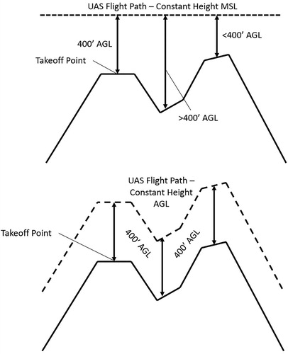
Another problem we encountered when mapping in locations with steep slopes was dealing with variable resolution and scale in the imagery. When the sensor is far from the ground, it produces an image of coarser spatial resolution (and smaller scale) than when it is flown close to the ground. In locations with extremely steep slopes, the ground may be both close and far within the mapping area, or even within the same image (e.g., ), resulting in variable scale and resolution. Apart from causing difficulties in post-processing (Ragg and Fey Citation2013), this phenomenon presents a challenge from a regulatory standpoint because Part 107 mandates a maximum flight altitude of 400 feet (122 m) AGL. At a topographically rugged site, this altitude rule may be quickly exceeded unintentionally if a “flat” flight plan is used (constant height MSL). To maintain safe and legal flight, mapping must be done in a way that maintains the altitude of the sUAS at a constant height AGL (). We searched for a mapping software application that could produce flight plans that would keep the Inspire 2 at 122-m AGL or below regardless of the terrain. The Map Pilot (MP) for DJI app was selected because it includes a terrain following mode. The elevation dataset used by the MP app is derived from the Shuttle Radar Topography Mission dataset collected by STS-99 in February 2000 (30-m spatial resolution). When the user identifies the location of the mapping flight (drawn in the app as a rectangle or polygon boundary feature) and specifies the desired forward overlap and sidelap, MP creates an elevation profile for the ground beneath the flight path and then calculates another elevation profile for the flight path to maintain a desired height AGL. We found this functionality to be reliable, even in terrain that included nearly vertical topography that we expected would confound the accuracy of the terrain-following mode.
Figure 4. Nadir aerial photograph showing trees along a steep slope (∼55° average). The top-right of the image has a finer scale (higher spatial resolution) than the bottom-left of the image due to the rapidly changing elevation. The changes in elevation are reflected in the relative sizes of the trees.
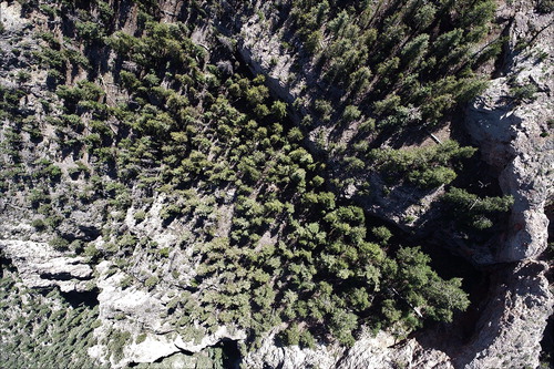
Figure 5. Diagram comparing UAS mapping missions flown at a constant height AGL (above ground level) versus a constant height MSL (above mean sea level). Flight at a constant height AGL (i.e., terrain following) allows the UAS to remain under the 400-foot (122 m) maximum altitude set by the FAA, even while navigating across rugged terrain, and mitigates problems related to variable scale and resolution.
The MP app and terrain-following feature generally functioned as advertised – we did experience an occasional problem (probably a software glitch) in which the Inspire 2 would reach the end of a flight line and pause for up to a minute before turning onto the next flight line and resuming the mission. This delay seemed especially pronounced when the sUAS needed to make an elevation adjustment as it proceeded to the next flight line. More than being a simple annoyance, this delay reduced the effective mapping endurance of the aircraft. The total flight endurance of the Inspire 2 was also visibly reduced by the terrain-following feature when compared with missions flown at a constant height MSL because of the additional battery capacity that was consumed to allow the UAS to climb and descend constantly throughout the flight.
Ground control
Due to the precision distance and area measurements that would be made from the imagery collected during this project, we implemented ground control at each site prior to mapping. After trial and error while testing various methods, we created the GCP boards described above. Transporting the boards around each site was made easier by loading them into a mainframe backpack designed for hunters to transport game meat. Using the supplied straps, we were able to attach a stack of 10–12 GCPs on the backpack frame. A team of two was required to accomplish each task when placing and measuring the GCPs. One team member carried the backpack with GCP boards, while the other carried the GPS receiver used to collect the coordinates at each location. The second team member also carried a hammer and stakes, and drove a stake into the ground through a hole in the center of the GCP board so it would not move during the mapping flight. We found this to be particularly important on steep slopes because GCPs can easily shift out of position if they are disturbed.
While very important to the overall goals of the project, the process of placing ground control targets was often tedious and difficult due to steep terrain. To streamline this process, prior to visiting each site, we would use GIS software to create a rough map of the site boundaries with intended GCP locations positioned at regular intervals. We used smartphone mapping apps (e.g., Collector for ArcGIS and Gaia GPS) to navigate to the desired positions for the GCPs. However, cliffs, scree slopes, and areas of bare rock often thwarted our efforts to place GCPs in the desired locations. We quickly learned to prioritize placing GCPs first near the corners of the site, then along the edges, and finally within the interior. This strategy seemed to improve global accuracy of the photogrammetric modeling of the scene in Pix4Dmapper, resulting in precisely georectified orthomosaics and digital surface models. If GCPs were only placed within the interior of the site and not at the corners and edges, local accuracy near the points tended to be adequate, but the global model accuracy often suffered.
Newer UAS such as the DJI Phantom 4 RTK offer near-direct georeferencing capabilities that may reduce the number of GCPs needed or eliminate them altogether. These systems work by communicating with an on-site GPS base station that has been left to average its signal over several minutes or hours, resulting in a highly accurate base point. The UAS measures its location relative to the base station to refine the accuracy of the geotags produced during the mission, which in turn results in a more accurate photogrammetric model in post-processing. We have not yet had the opportunity to use the Phantom 4 RTK, but we believe it could be very promising for precision mapping in mountainous areas with minimal GCPs.
Conclusions
We mapped seven subalpine forest sites using sUAS during 2017–2018 and encountered several challenges associated with mapping in mountainous locations. These challenges included weather factors and reduced aircraft performance at high altitudes, regulatory challenges related to flight altitude, line-of-sight issues, problems with variable resolution and scale, and difficulties with ground control placement over steep terrain. We learned how to overcome each of these problems using off-the-shelf or simple custom solutions to produce high-quality aerial image data at our study sites, and we believe these lessons we have outlined will be of great value to any research group conducting sUAS mapping operations in similar settings. We have found that sUAS are excellent platforms for remote sensing applications in mountainous areas, and we believe that this area of research is ripe for further development.
Acknowledgements
We would like to express our sincere thanks to Christopher Burchfield, James Burchfield, Nicole Burchfield, Ryan Howell, and Teresa Gómez for their assistance with sUAS flight operations.
Additional information
Funding
References
- Ambrosia, V. G., S. Wegener, T. Zajkowski, D. V. Sullivan, S. Buechel, F. Enomoto, B. Lobitz, S. Johan, J. Brass, and E. Hinkley. 2011. The Ikhana unmanned airborne system (UAS) western states fire imaging missions: From concept to reality (2006–2010). Geocarto International 26 (2):85–101. doi: 10.1080/10106049.2010.539302.
- Buhler, Y., M. S. Adams, A. Stoffel, and R. Boesch. 2017. Photogrammetric reconstruction of homogeneous snow surfaces in alpine terrain applying near-infrared UAS imagery. International Journal of Remote Sensing 38:3135–58. doi: 10.1080/01431161.2016.1275060.
- Crommelinck, S., R. Bennett, M. Gerke, F. Nex, M. Yang, and G. Vosselman. 2016. Review of automatic feature extraction from high-resolution optical sensor data for UAV-based cadastral mapping. Remote Sensing 8 (8):689. doi: 10.3390/rs8080689.
- De Michele, C., F. Avanzi, D. Passoni, R. Barzaghi, L. Pinto, P. Dosso, A. Ghezzi, R. Gianatti, and G. Della Vedova. 2016. Using a fixed-wing UAS to map snow depth distribution: An evaluation at peak accumulation. The Cryosphere 10 (2):511–22. doi: 10.5194/tc-10-511-2016.
- Eisenbeiss, H. 2009. UAV Photogrammetry. Dissertation, ETH Zurich.
- Gruen, A., Z. Zhang, and H. Eisenbeiss. 2012. UAV photogrammetry in remote areas – 3D modeling of Drapham Dzong Bhutan. Paper presented at XXII ISPRS Congress, Melbourne, Australia, August 25–September 1.
- Hardin, P. J., V. Lulla, R. R. Jensen, and J. R. Jensen. 2018. Small Unmanned Aerial Systems (sUAS) for environmental remote sensing: Challenges and opportunities revisited. GIScience & Remote Sensing 2018:1–12. doi: 10.1080/15481603.2018.1510088.
- Khot, L. R., S. Sankaran, A. H. Carter, D. A. Johnson, and T. F. Cummings. 2016. UAS imaging-based tools for arid winter wheat and irrigated potato production management. International Journal of Remote Sensing 37 (1):125–37. doi: 10.1080/01431161.2015.1117685.
- Laliberte, A. S., C. Winters, and A. Rango. 2011. UAS remote sensing missions for rangeland applications. Geocarto International 26 (2):141–56. doi: 10.1080/10106049.2010.534557.
- Linchant, J., J. Lisein, J. Semeki, P. Lejeune, and C. Vermeulen. 2015. Are unmanned aircraft systems (UASs) the future of wildlife monitoring? A review of accomplishments and challenges. Mammal Review 45 (4):239–52. doi: 10.1111/mam.12046.
- Mirijovsky, J., and J. Langhammer. 2015. Multitemporal monitoring of the morphodynamics of a mid-mountain stream using UAS photogrammetry. Remote Sensing 7:8586–609. doi: 10.3390/rs70708586.
- Pix4Dmapper User Manual v4.0. 2019. Accessed March 26, 2019. https://support.pix4d.com/hc/en-us/articles/204272989-Offline-Getting-Started-and-Manual-pdf-#gsc.tab=0.
- Ragg, H., and C. Fey. 2013. UAS in the mountains: Monitoring mountain rockslides using multi-temporal point clouds. GIM International 29–31.
- Shi, Y., J. A. Thomasson, S. C. Murray, N. A. Pugh, W. L. Rooney, S. Shafian, N. Rajan, G. Rouze, C. L. S. Morgan, H. L. Neely, et al. 2016. Unmanned aerial vehicles for high-throughput phenotyping and agronomic research. PloS ONE 11 (7):e0159781. doi: 10.1371/journal.pone.0159781.
- Silvagni, M., A. Tonoli, E. Zenerino, and M. Chiaberge. 2017. Multipurpose UAV for search and rescue operations in mountain avalanche events. Geomatics, Natural Hazards and Risk 8 (1):18–33. doi: 10.1080/19475705.2016.1238852.
- Syromyatina, M. V., Y. N. Kurochkin, D. P. Bliakharskii, and K. V. Chistyakov. 2015. Current dynamics of glaciers in the Tavan Bogd Mountains (Northwest Mongolia). Environmental Earth Sciences 74 (3):1905–14. doi: 10.1007/s12665-015-4606-1.
- Tang, L., and G. Shao. 2015. Drone remote sensing for forestry research and practices. Journal of Forestry Research 26 (4):791–7. doi: 10.1007/s11676-015-0088-y.
- Westoby, M. J., J. Brasington, N. F. Glasser, M. J. Hambrey, and J. M. Reynolds. 2012. Structure-from-Motion’ photogrammetry: A low-cost, effective tool for geoscience applications. Geomorphology 179:300–14. doi: 10.1016/j.geomorph.2012.08.021.
- 14 C.F.R. Part 107. 2016. United States of America.