
Abstract
Skin markers (SMs) are usually used as fiducial points in registration of neuronavigation, but the areas in which they can be adhered to are restricted, which usually results in poor distribution of the SMs and a large registration error. In this research, we studied whether the registration accuracy can be improved by adding anatomical landmarks (ALs), which are thought to have a larger localization error than SMs. A series of random SM configurations were generated, and for each SM configuration, we generated a corresponding SM-AL configuration by adding several ALs. We then compared the accuracy of the point-matching registration of the SM configurations with that of the corresponding SM-AL configurations. Experiment results indicated that adding ALs always made the mean target registration error of the whole head fall into a lower and narrower range, which meant that the registration became more accurate and more stable. In addition, adding more ALs resulted in a better performance.
Introduction
Neuronavigation systems have been widely used to guide neurosurgeons during surgery by establishing a spatial correspondence between the patient and his images. The process of establishing spatial correspondence is called registration, and it is both the basis of neuronavigation and one of the major sources of errors.[Citation1,Citation2]
Point-matching and surface-matching are two types of methods that are used for registration of neuronavigation, and the first kind, point-matching, is more widely used clinically.[Citation3] In point-matching, the surgeons first select a set of fiducial points on the images and then select a set of spatially corresponding points on the patient’s head. After the points have been selected, closed form methods can be used to calculate a rigid spatial transformation to align the corresponding points so that when they are transformed into the same coordinate system, the root mean square distance between the corresponding points is minimized.[Citation4] The spatial transformation calculated by this type of registration establishes spatial correspondence between the patient and the images.
There are some natural anatomical landmarks (ALs) on the surface of the head that can be used as fiducial points, such as the nose tip, nasion, bilateral lateral canthus, bilateral tragus and so on. However, both the number and the distribution of the ALs are highly restricted, and the error involved in localizing them is usually large. Therefore, in the clinical setting, the point-matching is rarely performed using only ALs, and artificial fiducial points are commonly utilized. Currently, skin markers (SMs) are widely used as artificial fiducial points because they are not invasive and are only a minor inconvenience to the patient.
The spatial distribution of the fiducial points has a significant influence on the registration accuracy in point matching.[Citation5] Though there has been many research on how to achieve a good spatial distribution of the SMs,[Citation6–11] one of the biggest problem in using SMs is still not solved, that is the restricted area to which the SMs can be adhered. For example, surgeons usually do not adhere SMs to the face or the occipital region to avoid possible displacement from the time of image scanning to the time of registration. To some extent, this restriction may lead to a poor configuration of the fiducial points, which tends to increase the registration error.[Citation5] On contrast, most ALs reside in regions in which SMs cannot be applied, and adding some ALs as fiducial points can help improve the fiducial configuration by enlarging its distribution area, thereby improving registration accuracy. However, the effect of adding ALs is twofold, as the error of localizing ALs is usually larger than that of SMs, and a larger localization error will tend to result in a larger registration error.[Citation5,Citation7] To date, it is unknown whether adding several ALs will improve or decrease the registration accuracy of point-matching in neuronavigation.
The objective of this study is to answer this question by simulating the point-matching process in the image space.
Materials and methods
Three definitions of errors in point-matching spatial registration
In neuronavigation, the coordinate system of the images is called the image space, and the coordinate system of the patient’s head is called the patient space. Accordingly, spatial registration is to calculate a rigid transformation between these two spaces. Three definitions of errors are usually used in point-matching: the fiducial localization error (FLE), the fiducial registration error (FRE), and the Target Registration Error (TRE).[Citation12] In the rigid spatial registration of two spaces, for each point in one space, there is only one true corresponding point in the other space. The FLE is defined on fiducial points, and when the position of a fiducial point is determined in one space, the FLE of the point is the distance between its true corresponding point and the corresponding point that is selected by the surgeon in the other space. After registration, every point in one space can be transformed into a point in the other space, which is called the registered point. The FRE is also defined on fiducial points, and it is the distance between a fiducial point’s registered point and its corresponding point that is selected in the other space. The TRE can be defined on any point, and for an arbitrary point in one space, the TRE is the distance between its true corresponding point and its registered point in the other space.
The FLE is the fundamental reason of registration errors in point-matching. It is widely accepted that the FLE of ALs is generally larger than that of SMs, although it is impossible to measure the exact value of the FLE in real clinical applications. The TRE in the region of interest is most relevant to surgeons who use neuronavigation systems. The TRE at a specific target point is determined by many factors, such as the position of the target point, the number and distribution of the fiducial points, and the FLE.[Citation5] Therefore, the TRE may be quite different at different positions, even in the same registration, and similar to the FLE, we can neither calculate nor measure the exact value of the TRE at a specific target point in real clinical applications. The FRE is a value that we can calculate in each registration, and many neuronavigation systems return the mean FRE as a feedback to assess the registration accuracy. However, the mean FRE only expresses how the corresponding fiducial points are aligned with each other and provides little information on the TRE of other points.[Citation5,Citation7]
To calculate the exact TRE at every point and use the results as the basis of evaluating registration accuracy, we simulated point-matching spatial registration in the image space. At the same time, we could not use the TRE of one point to compare the accuracy between different registrations because the TRE distributions of different registrations may be significantly different from each other. Therefore, we calculated the mean TRE of all the voxels in the head and used the result as the criteria for evaluating registration accuracy.
Point-matching simulation and accuracy analysis
We simulated the point-matching process using the following steps. First, we selected a set of n points, X = x1, x2, ⋯, xn\}, to represent the fiducial points selected in the image space. Next, we generated a random rigid transformation Ttrans and transformed each point in X with it to obtain a new point set, Y = \{y1, y2, ⋯, yn\}, representing the actual corresponding point set in the patient space, where yi = Ttrans xi (i = 1, 2, ⋯, n) is the point that corresponds to the point xi. Then, we added a random perturbation to each point in Y to obtain a new point set, Y' = \{y1 ', y2 ', ⋯ , yn '\}. This new point set was used as the corresponding point set that was selected in the patient space, and the distance between yi and yi ' was the FLE of the ith fiducial point. Finally, we registered the point set X with the point set Y' and calculated a new spatial transformation from the image space to the patient space, Treg. Therefore, the TRE of a point p in the image space could be calculated as ∥ Ttrans p - Treg p ∥. We denoted the mean TRE of all the voxels in the head as TREv.
In the above process, a random perturbation was introduced to a point by adding the random value cΔ y to each coordinate of the point, where c was a constant and Δ y∼N(0, 1). The unit of Δ y was millimeters. When we added the perturbation to the SMs, the constant c was set to two, which resulted in an FLE with an expected value of approximately 3.2 mm. When we added the perturbation to the ALs, c was set to three, which resulted in an FLE with an expected value of approximately 4.8 mm.
To compare the registration accuracy before and after adding the ALs, we first randomly selected SMs according to some spatial distribution rules to form a fiducial configuration Csm containing only SMs. We then added several ALs to the Csm to form a new fiducial configuration Cal, which contained both the SMs and the ALs. For each Csm and the corresponding Cal, we simulated the point-matching registration described in the previous paragraph 1000 times and calculated the mean TREv for Csm and Cal. The means of the 1000 TREv of the Csm and Cal were denoted as TREcsm and TREcal, respectively.
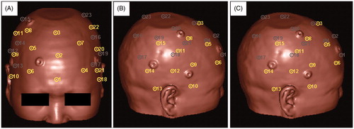
The spatial distribution rules for randomly generating Csm were based on the group of SM candidates illustrated in . We divided the area of the surface of the head that was suitable for applying SMs into three regions – the Left, Right, and Anterior Regions – and then placed eight, eight, and seven SM candidates, respectively, in each region. We evenly distributed the SM candidates throughout each region and made them cover the entire region. Neighboring SM candidates were kept a reasonable distance from each other so that we were able to randomly select SMs from each region without worrying about selecting two SMs that were too close to each other. In the following experiment, we used [Nl, Nr, Na] to express the spatial distribution rule for randomly generating a Csm, where Nl, Nr, and Na were the number of points selected from the Left, Right, and Anterior Regions, respectively. All of the Csm that were generated following the same rule were considered to be of the same type. We generated 100 ←Csm following the same spatial distribution rule and 100 corresponding Cal and compared the statistical distribution of the TREcsm and the TREcal to determine whether adding ALs could help improve registration accuracy.
Figure 1. Candidate SMs on the surface of the head viewed from three different directions. Each circle with a dot in it represents a candidate SM, and the dot is in the exact position of the candidate. The yellow and the gray colors indicate the visible and the invisible candidates, respectively, in the current direction of view. The candidates are numbered from 1 to 23. The Anterior Region contains candidates Nos. 1 to 7. The Right Region contains candidates Nos. 8 to 15. The Left Region contains candidates Nos. 16 to 23.
Simulation of adding facial ALs
In this experiment, we studied how the registration accuracy was influenced by the addition of different combinations of facial ALs (nose tip, nasion and bilateral lateral canthus) when the initial Csm contained different numbers of SMs in the Anterior Region and a fixed number of SMs in the Left and the Right Regions. We studied three types of Csm: [3,3,0], [3,3,1] and [3,3,2]. For each type of Csm, we added three different combinations of facial ALs: one AL (nose tip), two ALs (nose tip and nasion) or three ALs (nose tip, nasion and bilateral lateral canthus).
Simulation of adding lateral ALs
In this experiment, we studied how the registration accuracy was influenced by the addition of different combinations of lateral ALs (left tragus and left lateral canthus) when the initial Csm contained different numbers of SMs in the Left Region and a fixed number of SMs in the Right and the Anterior Regions. We studied four types of Csm: [0,3,2], [1,3,2], [2,3,2] and [3,3,2]. For each type of Csm, we added two combinations of lateral ALs, either one AL (left tragus) or two ALs (left tragus and left lateral canthus).
Simulation of adding central and posterior ALs
In this experiment, we studied how the registration accuracy was influenced by the addition of different combinations of central and posterior ALs (inion and bilateral tragus) when the initial Csm contained different numbers of SMs in each region. We studied four types of Csm: [3,3,2], [3,2,2], [2,2,2] and [2,2,1]. For each type of Csm, we added two combinations of central and posterior ALs, either one AL (inion) or three ALs (inion and bilateral tragus).
Results
Simulation of adding facial ALs
The distributions of the TREcsm of SM configuration types [3,3,0], [3,3,1] and [3,3,2] and the TREcal of the corresponding fiducial configurations obtained by adding different combinations of facial ALs are illustrated in . Regardless of the presence of SMs in the Anterior Region, the TREcal of the configurations with additional facial ALs always falls into a lower and narrower range than the TREcsm of the corresponding configuration using only SMs. In addition, for a specific type of SM configuration, adding more facial ALs resulted in a lower and narrower range of the TREcal distribution. By comparing , we can also find that as the number of SMs in the Anterior Region increases, the improvement in the registration accuracy caused by adding facial ALs become less significant.
Figure 2. Box plots of the TREcsm of three different types of SM configurations and the TREcal of the corresponding configurations after the addition of different combinations of facial ALs. The TREcsm is depicted in red, and the TREcal is depicted in blue. The horizontal axis indicates three different combinations of ALs. A, B, and C are the plots for the SM configuration types: [3,3,0], [3,3,1], and [3,3,2], respectively. The ends of the whiskers represent the 5th and the 95th percentiles.
![Figure 2. Box plots of the TREcsm of three different types of SM configurations and the TREcal of the corresponding configurations after the addition of different combinations of facial ALs. The TREcsm is depicted in red, and the TREcal is depicted in blue. The horizontal axis indicates three different combinations of ALs. A, B, and C are the plots for the SM configuration types: [3,3,0], [3,3,1], and [3,3,2], respectively. The ends of the whiskers represent the 5th and the 95th percentiles.](/cms/asset/8e98c6a1-b09f-4b65-93b4-ab8db3229257/icsu_a_1180429_f0002_c.jpg)
Simulation of adding lateral ALs
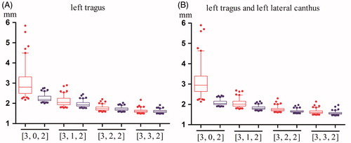
The distributions of the TREcsm of SM configuration types [0,3,2], [1,3,2], [2,3,2] and [3,3,2] and the TREcal of the corresponding fiducial configurations obtained by adding different combinations of lateral ALs are illustrated in . Regardless of the presence of SMs in the Left Region, the TREcal of configurations with additional left lateral ALs always falls into a lower and narrower range than the TREcsm of the corresponding configurations using only SMs. However, as the number of SMs in the Left Region increases, the TREcsm of the registration performed using only SMs become smaller, and the improvement in registration accuracy caused by adding the left lateral ALs become less significant. In addition, by comparing , we can observe that for a specific type of SM configuration, the difference between adding one AL and adding two ALs is not significant.
Figure 3. Box plots of the TREcsm and the TREcal after the addition of two different combinations of left lateral ALs. The TREcsm is depicted in red, and the TREcal is depicted in blue. The horizontal axis indicates four types of SM configurations. (A) A plot of the four types of configurations with only SMs and the corresponding configurations after adding the left tragus. (B) A plot of the four types of configurations with only SMs and the corresponding configurations after adding the left tragus and the left lateral canthus. The ends of the whiskers represent the 5th and the 95th percentiles.
Simulation of adding central and posterior ALs
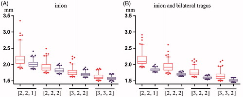
The distributions of the TREcsm of SM configuration types [2,2,1], [2,2,2], [3,2,2] and [3,3,2] and the TREcal of the corresponding fiducial configurations obtained by adding different combinations of central and posterior ALs are illustrated in . indicates that registration accuracy can be improved by adding the inion alone, and indicates that the range of the TREcal becomes lower and narrower when the bilateral tragus ALs are added. Once again, as the number of SMs increases, the improvement in registration accuracy caused by adding the central and posterior ALs becomes less significant.
Figure 4. Box plots of the TREcsm and the TREcal after the addition of two different combinations of central and posterior ALs. The TREcsm is depicted in red, and the TREcal is depicted in blue. The horizontal axis indicates four types of SM configurations. (A) A plot of the four types of configurations with only SMs and the corresponding configurations after adding the inion. (B) A plot of the four types of configurations with only SMs and the corresponding configurations after adding the inion and bilateral tragus. The ends of the whiskers represent the 5th and the 95th percentiles.
Discussion
In the clinical application of neuronavigation systems, spatial registration is usually implemented using the point-matching method, which calculates a rigid spatial transformation between the patient space and the image space by matching corresponding fiducial points in these two spaces. The registration accuracy of point-matching depends on many factors, such as the number and distribution of the fiducial points, the FLE, and the position of the point of interest. Both ALs and artificial SMs can be used as fiducial points, but the number and distribution of ALs are limited, and the FLE of ALs is usually larger than that of SMs. Therefore, it is rare to use only ALs for point-matching, but they can be used to complement SMs. To the best of our knowledge, there are no studies that examine how registration accuracy is influenced when ALs are added. One of the reasons for the lack of this type of studies may be the difficulty in measuring the exact FLE and the exact TRE during clinical applications of neuronavigation.
In this study, we simulated the point-matching process in the image space, and this enabled us to be able to calculate the exact TRE of all the points that we were interested in. In addition, we calculated the mean TRE of all the voxels in the head and used the results as criteria of the registration accuracy to avoid bias resulting from the differences in the TRE at different positions. We divided the areas of the head in which SMs could be adhered to into three regions and placed several SM candidates in each region. Then, we generated fiducial configurations using only SMs by randomly selecting SM candidates from each region to avoid bias from a specific SM configuration. We classified the ALs into three groups: facial ALs, lateral ALs, and central and posterior ALs. For each group of ALs, we randomly generated SM configurations and simulated the registrations before and after the addition of different combinations of ALs. The mean TRE was calculated and analyzed to study the influence of adding ALs on the registration accuracy.
Our results indicate that adding ALs always causes the registration error to fall into a lower and narrower range, which means that adding ALs makes the registration more accurate and more stable. In addition, for each group of ALs, the addition of more ALs always outperformed the addition of fewer ALs. We also noted that for the facial and lateral ALs, the efficacy of adding ALs decreased when the number of SMs increased on the corresponding side. Specifically, the efficacy of adding facial ALs became less significant when the number of SMs in the Anterior Region was increased to two, and the efficacy of adding the left lateral ALs became less significant when the number of SMs in the Left Region was increased to two or three. For the central and posterior ALs, the experimental results showed that adding the inion always improved the registration accuracy, which might be because there is no SM near the location of the inion. In clinical practice, SMs cannot be adhered to the occipital region, as they would be displaced when the patient lies down for image scanning.
One of the limitations of this study is that we could not obtain the exact FLE of the SMs and ALs. Instead, we simulated an FLE with an expectation of 3.2 mm for the SMs and an expectation of 4.8 mm for the ALs. It is impossible to measure the actual FLE in clinical applications of neuronavigation, and to the best of our knowledge, there are no publications concerning the actual distribution of the FLE of different types of fiducial points in clinical applications. Many random factors contribute to the final FLE, such as the image resolution, SM/AL position and orientation, accuracy of the navigation pointer used to record SM/AL position in the patient space and human error. Because of the lack of a reliable prior distribution of FLE, we chose the Gaussian distribution as an approximation. The parameter values of the Gaussian distribution that we used here comply with the experiences of the users of neuronavigation systems, and the resulting FREs were consistent with the clinical experience when SMs or both SMs and ALs were used for point-matching. Therefore, we believe that our simulation of the FLE is realistic. More reliable data on the distribution of the FLE in clinical practice will not only be very helpful for improving the results of our study but will also be useful for further studies of other properties of the point-matching method.
We did not include phantom or clinical experiments in this study because we wanted to highlight the influence of the ALs and exclude the influence of other factors. In phantom or clinical experiments, the TRE will be affected by many factors, such as the precision of the tracking system and the tools, the number and the distribution of the fiducial points, the position of the target, and possible human error. Therefore, the true influence of the ALs may be obscured by other errors. We will design dedicated head phantom and conduct careful phantom and clinical experiments in the future to study how the finding could be transferred into clinical environment.
We should also note that regardless of whether SMs or ALs are used, the accurate localization of the fiducial points in both the image space and the patient space is the basis of accurate registration. Therefore, if it is difficult to accurately localize a specific AL for imaging or anatomical reasons, it should not be used for point-matching registration. In addition, different kinds of neurosurgery have different requirements on the registration and application accuracy of neuronavigation system. For example, a 2-mm accuracy would be sufficient for most craniotomy, higher accuracy may be required for biopsy or deep brain stimulation. According to this study, registration accuracy can be improved by adding ALs, but the decision about whether the finial application accuracy is enough for a specific surgery should be made by according to each center’s original guideline.
Conclusions
Adding ALs can help to improve registration accuracy when using the point-matching method in neuronavigation, especially when the ALs are on the side of the head, in which the number of SMs is small.
Funding information
This study is partly supported by Project 81471758 and 81271670 of National Natural Science Foundation of China, National Science and Technology Support Program (No. 2015BAK31B01) and Science and Technology Commission of Shanghai Municipality (Nos. 15441905500 and 16XD1424900).
Disclosure statement
The authors report no conflicts of interest. The authors alone are responsible for the content and writing of this article.
References
- Cleary K, Peters TM. Image-guided interventions: technology review and clinical applications. Annu Rev Biomed Eng. 2010;12:119–142.
- Wang MN, Song ZJ. Classification and analysis of the errors in neuronavigation. Neurosurgery. 2011;68:1131–1143.
- Eggers G, Muhling J, Marmulla R. Image-to-patient registration techniques in head surgery. Int J Oral Maxillofac Surg. 2006;35:1081–1095.
- Eggert DW, Lorusso A, Fisher RB. Estimation 3-D rigid body transformation: a comparison of four major algorithms. Mach Vis Appl. 1997;9:272–290.
- Fitzpatrick JM, West JB, Maurer CR. Predicting error in rigid-body point-based registration. IEEE Trans Med Imaging. 1998;17:694–702.
- West JB, Fitzpatrick JM, Toms SA, et al. Fiducial point placement and the accuracy of point-based, rigid body registration. Neurosurgery. 2001;48:810–816.
- Wang MN, Song ZJ. Improving target registration accuracy in image-guided neurosurgery by optimizing the distribution of fiducial points. Int J Med Robot. 2009;5:26–31.
- Shamir RR, Joskowicz L, Shoshan Y. Fiducial optimization for minimal target registration error in image-guided neurosurgery. IEEE Trans Med Imaging. 2012;31:725–737.
- Battezzato A, Gastaldi L, Pastorelli S. Evaluation of the factors affecting the optimal fiducial configurations calculated through a genetic-algorithm-based methodology in image-guided neurosurgery. Int J Med Robot. 2011;7:441–451.
- Wang MN, Song ZJ. Distribution templates of the fiducial points in image-guided neurosurgery. Neurosurgery. 2010;66:143–150.
- Wang MN, Song ZJ. Guidelines for the placement of fiducial points in image-guided neurosurgery. Int J Med Robot. 2010;6:142–149.
- Maurer CR, Fitzpatrick JM, Wang MY, et al. Registration of head volume images using implantable fiducial markers. IEEE Trans Med Imaging. 1997;16:447–462.