
Abstract
Surgical navigation systems can assist doctors in performing more precise and more efficient surgical procedures to avoid various accidents. The near-infrared optical system (NOS) is an important component of surgical navigation systems. However, several surgical instruments are used during surgery, and effectively tracking all of them is challenging. A stereo matching algorithm using two intersecting lines and surgical instrument codes is proposed in this paper. In our NOS, the markers on the surgical instruments can be captured by two near-infrared cameras. After automatically searching and extracting their subpixel coordinates in the left and right images, the coordinates of the real and pseudo markers are determined by the two intersecting lines. Finally, the pseudo markers are removed to achieve accurate stereo matching by summing the codes for the distances between a specific marker with the other two markers on the surgical instrument. Experimental results show that the markers on the different surgical instruments can be automatically and accurately recognized. The NOS can accurately track multiple surgical instruments.
Introduction
In traditional surgery, both surgical planning and implementation rely on the knowledge of the lesion region and the clinical experience of the doctors. Moreover, given some lesion regions, like the brain and spine, are indistinct, doctors perform surgery only according to the pathological features of the lesion regions. However, the uncertainty of this method may result in complicated surgical procedures, huge operation wounds and long recovery times. With the developments in science and technology, surgery has gradually become more precise and less invasive. Over the past few years, computer technology, precision instruments and digital image technology have been rapidly developed. These technologies have been introduced to the medical field, breaking new ground in surgery. Consequently, computer-aided surgery (CAS) is launched.[Citation1–5] CAS follows a certain procedure. First, with the use of advanced imaging devices in medicine, such as MRI and CT, multi-mode image data of a patient is obtained and subjected to processing, such as image segmentation, image fusion, or three-dimensional reconstruction, with the assistance of computers. Second, a rational and quantitative operation plan to achieve minimal invasion is developed based on the clinical experience of the doctor and the analysis of the pathological features of the lesion region. Finally, after simulating the surgical procedure, the doctor can actually perform the operation aided by a video monitoring system and stereotaxic device. With the rapid development in CAS, it has been used in neurosurgery,[Citation6,Citation7] plastic surgery,[Citation8,Citation9] osteopathy [Citation10–12] and otolaryngology,[Citation13] among other medical fields. As an important tool in CAS, a surgical navigation system (SNS) can show the location and direction of surgical instruments relative to the lesion region to guide surgical operations with real-time images.[Citation14] Since the introduction of the first SNS more than 20 years ago, SNS technologies have likewise undergone rapid development, significantly improving the accuracy of lesion localization, reducing surgical injuries, optimizing surgical pathways and increasing operative success rates.[Citation15–17] Tracking technology, particularly near-infrared tracking technology, is one of the key technologies used in SNSs.[Citation18,Citation19] It is extensively applied to SNSs because of its convenience, reliability and accuracy. Near-infrared cameras are also used in SNSs to capture surgical instruments.[Citation20] These cameras can filter ambient light and reduce noises caused by lights to detect markers on surgical instruments precisely. During tracking, the three-dimensional coordinates of each marker can be calculated by finding the matching relationship between the markers on a surgical instrument and the points in the right and left images. The space coordinates of the tip of the surgical instrument can be obtained by computing the coordinates of each marker. Therefore, matching markers is a crucial function of a near-infrared optical system (NOS). However, multiple surgical instruments are always used in CAS; as a result, numerous points appear in the right and left images when the instruments are captured. The multitude of points usually leads to identification difficulties, making correct matching difficult to achieve. Thus, an effective, precise and quick stereo matching algorithm is imperative.
Stereo matching refers to the search for corresponding relations between pixels of the same object in the same space but from different viewpoints. In stereoscopic vision, stereo matching means finding the corresponding relations between targets of interest in the right and left images captured by two or more cameras. Unfortunately, geometric information, grayscale distortion and noise jamming occur in the two images when stereo matching is implemented, complicating stereo matching. Stereo matching is currently implemented under specific conditions. Over the past several years, various algorithms and strategies have been proposed for stereo matching.[Citation21–25] Stereo matching has two main modes: matching based on characteristics [Citation26,Citation27] and matching based on regions.[Citation28,Citation29] Both modes can be used for stereo matching of images or markers, but they differ in terms of accuracy, effectiveness and speed. Furthermore, only multiple points exist in the images of surgical instruments, which are captured in an NOS, and these points have few edge differences and are in grayscale. As a result, matching points by the two traditional modes of stereo matching is difficult. Methods of ordering constraints and epipolar constraints have been adopted in stereo matching for points in binocular vision.[Citation30,Citation31] However, surgical instruments move in different directions and occupy different positions during surgeries. As a result, the locations of the corresponding points in the right and left images are inconsistent. Therefore, correctly matching all points by methods of ordering constraints and epipolar constraints is difficult. At present, the clinical measuring equipment for NOSs tends to avoid the process of stereo matching. For example, Northern Digital Inc. (NDI) offered a solution[Citation32]: a control emitter is installed in the tracking system to activate points one by one within a certain time interval, that is, only one point is activated each time, and near-infrared light is emitted. With only one point presented in the pair of images, the space coordinates of the point can be directly computed. However, this procedure is considerably complex. The timing sequence must be synchronous with the camera. Furthermore, this solution will increase the development cost of the navigation system and prolong the development period. Moreover, the physical connection between markers and the emitter is inconvenient when performing surgeries. Therefore, the stereo matching of points and the automatic recognition of surgical instruments are crucial to realize the function of NOSs fully.
Methods
The NOS construction
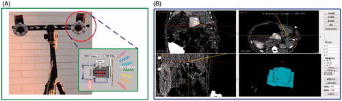
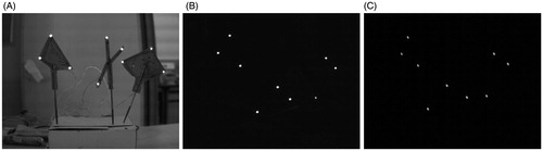
The NOS in an SNS is required to track an instrument and provide real-time positioning information. Near-infrared filter technology is used in ordinary optical camera to construct the NOS more easily at a reduced cost. The NOS is divided mainly into two: the software component and hardware part (). The NOS works as follows. First, when the system is initiated, the markers on the surgical instruments emit light waves. Second, the cameras capture all the markers and send the image data to the computer via USB interface. Third, the computer automatically finds all points and determines the point centers at the subpixel level. Fourth, the space coordinates of the markers are computed based on the internal and external parameters of the camera.[Citation18] Fifth, the locations and directions of the tips of the surgical instruments are determined. Finally, the surgical instruments can be tracked in real time as they register in the coordinate systems.
Figure 1. NOS: (A) system hardware; (B) navigation software.
Stereo matching and recognition of surgical instruments
The core functions of an SNS are to obtain the real-time locations of the surgical instruments and show the relative positions of instruments and surgical sites to guide doctors during surgeries. In the tracking of surgical instruments, that is, computing their coordinates in real time, the markers should first be stereo matched. Therefore, the stereo matching of markers is a crucial step. In this study, an NOS aided by two near-infrared cameras is developed. The system model is shown in .
Figure 2. System model.
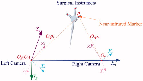
As shown in , Ωl(Xl, Yl, Zl), Ωr(Xr, Yr, Zr) and Ωg(Xg, Yg, Zg) stand for the coordinates in the right and left cameras and the world coordinates, respectively. Xr and Yr are on the image plane of the right camera, and Zr overlaps with the optical axis of the camera lens. Or is the center point of the optical axis of the right camera. The same method is applied to identify the coordinate system of the left camera. Og is the original point of the left camera Ol, and the linking line between Ol and Or is in the direction of Xg of the world coordinates. Xg, Zl, Zg and Xg are located on the same plane. The relations of these three coordinates can be expressed as follows:
(1)
(2)
(3)
In EquationEquations (1)–(3), pg, pl and pr represent the coordinates of a point in the three-coordinate systems; Rlg and Rrg and Tlg and Trg represent the rotation matrices and translation matrices, respectively, which are the transformation from Ωl and Ωr to Ωg. Rlr and Tlr represent the rotation matrix and translation matrix, respectively, which are the transformation from Ωl to Ωr.
Optical relationship
Let p be a marker in Ωg. The subpixel coordinates of p in the right and left images are al and ar, respectively. Stereo matching is finding the corresponding relation between al and ar. For the left camera, matrix Gl is obtained after calibration. Assuming that al= [ual, val]T, the normalized coordinate vector cl= [ucl, vcl]T and al satisfy the following equation:
(4)
If the lens distortion of the near-infrared camera is considered,[Citation18] the corresponding relation between cl and the ideal normalized coordinate vector fl= [xl, yl]T can be expressed as
(5)
(6)
where ex is the tangential distortion vector, rl2 = xl2 + yl2, and βli is the lens distortion coefficient. First, fl is initialized to cl, and then the approximate value of fl is obtained by iterative calculation. Given fl is the normalized image projection, coordinate pl of p in Ωl satisfies the following relation:
(7)
where κl is an arbitrary value. Assuming Wl= [xl, yl, 1]T, EquationEquation (7)
(7) can be simplified as follows:
(8)
In , straight lines Olpl in Ωl can be represented by EquationEquation (8)(8) . Similarly, straight lines Orpr in Ωr can be represented by
(9)
Substituting EquationEquation (8)(8) into EquationEquation (2)
(2) derives the following equation:
(10)
Similarly, substituting EquationEquation (9)(9) into EquationEquation (3)
(3) derives the following equation:
(11)
The direction vectors of straight lines Olpl and Orpr in Ωg are denoted by jl=RlgWl and jr=RrgWr. The direction vector of OlOr in the X-axis of Ωg is denoted by jo. Straight lines Olpl and OlOr constitute plane Πlpr, whose normal vector n can be derived using the following equation:
(12)
Given both pr and pl originate from p, that is, straight lines Olpl and Orpr cross at p in Ωg, Orpr is also on plane Πlpr; thus,
(13)
According to EquationEquations (4)–(12), a subpixel coordinate point represents a straight line in Ωr. If two lines corresponding to the two subpixel coordinates in the right and left images originate from the same marker, then they intersect and satisfy EquationEquation (13)(13) . However, the satisfaction of EquationEquation (13)
(13) does not mean that both lines absolutely originate from the same marker. Moreover, both lines certainly do not originate from the same marker if they do not satisfy EquationEquation (13)
(13) .
Stereo matching based on codes
Assuming four markers represented by pi (i = 1, 2, 3, 4) exist, as shown in , and p1, p2 and p3 are located on the same surgical instrument, the instrument can be tracked by tracking p1, p2 and p3. The subpixel coordinates of marker pi in the right and left images are ali and ari, respectively. According to EquationEquations (4)–(11), the straight lines of ali and ari in Ωg are Olpli and Orpri, whose direction vectors are jli and jri, respectively. To illustrate the principle of stereo matching based on codes, matching p3 is taken as an example. The subpixel coordinates of p3 are al3 and ar3. Space matching for p3 means finding the correct corresponding relation between al3 and ar3 in all the subpixel coordinates. The direction vectors of straight lines Olpl3 and Orpr3 in Ωg are denoted by jl3 and jr3. Line Olpl3 and line OlOr constitute plane Πl3pr.
Figure 3. Stereo matching: (A) p1, p2 and p4 are beyond plane Πl3pr; (B) p1 is on plane Πl3pr.
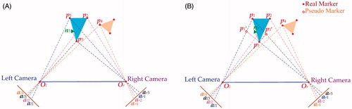
(1) When p1, p2 and p4 are beyond plane Πl3pr ()
According to EquationEquations (4)–(11), the direction vectors of markers p1, p2 and p4 in Ωg are jr1, jr2 and jr4, and the normal vector of Πl3pr is n3 according to EquationEquation (12)(12) . Into the following equation, jr1, jr2, jr3 and jr4 are incorporated to obtain the value of μ:
(14)
Owing to the influence of calculation errors, even if pi is on plane Πl3pr, μ cannot be zero but can only be approximated to zero. Therefore, if μ is less than the stipulated threshold value μc, then μ satisfies EquationEquation (14)(14) , that is, the subpixel coordinate ar of jr in the right image and the subpixel coordinate al in the left image originate from the same p. Therefore, only jr3 satisfies EquationEquation (14)
(14) , whereas jr1, jr2 and jr4 do not. As a result, the correct matching relation for p3 between the right and the left images can be obtained.
(2) When at least one among p1, p2 and p4 is on plane Πl3pr ()
Assuming that p1 exists on plane Πl3pr, that is, points p1, p3, Ol and Or are all on the same plane, the normal vector of the plane is perpendicular to all the straight lines inside the plane when matching p1 and p3. Moreover jr1 and jr3 satisfy EquationEquation (14)(14) . Two real markers, i.e. p1 and p3, and two pseudo markers, i.e. p1′ and p3′, can be obtained. The surgical instruments should be assigned codes, i.e. the markers on the instruments and the distance between them should be assigned codes to eliminate pseudo markers.
The distances between two markers on the surgical instruments are already known. At least three markers should be installed on a surgical instrument, and the distance between these markers should be unequal. If the distance between two markers is d, then D is used to represent the set of all distances between markers (d). The unicity of the distances between the markers on the surgical instruments has to be represented with codes to distinguish the distances between markers. Represented by k, the method of coding is as follows:
(15)
The sum of the codes for two distances is the code for the marker they share. As shown in EquationEquation (15)(15) , the code for each distance is unique; thus, the codes for the markers determined by the distance codes are likewise unique. The steps in matching subpixel coordinates in the right and left images by distance restriction are as follows:
Step 1: On the basis of EquationEquation (10)(10) and Equation(11)
(11) , the coordinates of all the markers (including real markers and pseudo markers) that satisfy EquationEquation (14)
(14) are determined. The distances between markers are then computed using the Euclidean distance. Finally, the distance matrix W is obtained, with each distance denoted by w.
Step 2: The distance matrix W is scanned. The w and d values of the surgical instruments are substituted into the following equation:
(16)
In consideration of the measuring errors, φ is set to be the permissible error range. If w and d satisfy EquationEquation (16)(16) , then the two markers related to distance w are temporarily considered being on a certain instrument, and then distance code jn is recorded. Finally, after scanning, the upper triangular matrix U, which involves all distance codes, is obtained, and S=U+UT.
Step 3: The sum of every two distance codes in each line or column of the diagonal matrix S is determined and then compared with the codes for the markers. If they are equal, the marker is real. Through this step, the system can distinguish all real markers; achieve correct matching between points in the right and left images; determine the matching relation between the markers on the surgical instruments and their points in the images; and record the corresponding distance codes during the process of scanning, that is, confirm which codes belong to which instrument for instrument recognition and tracking.
Results and discussion
Single surgical instrument
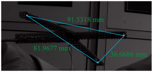
To verify the tracking accuracy of our NOS, we have designed a surgical instrument equipped with three near-infrared markers. As shown in , the distances between two markers are 81.626, 91.496 and 36.482 mm. The distances are obtained by measuring with a vernier caliper with an accuracy of 0.02 mm and computing the center of the physical markers for a dozen times.
Figure 4. Distances between two markers on a surgical instrument.
First, the instrument is placed within the view of the NOS. Next, 20 pairs of images of the instrument are taken from different positions. Finally, the subpixel coordinates of the three markers are determined. The measurement results are shown in , in which ali(x, y) and ari(x, y) (i = 1, 2, 3) stand for the subpixel coordinates of all the points in the right and left images, respectively. Afterward, the correct matching relation of the three markers can be obtained.
Table 1. Subpixel coordinates and matching relation of all the points.
Through EquationEquations (4)–(11), plane Πlpr1, plane Πlpr2 and plane Πlpr3, which are constructed by OlOr with Olp1, Olp2 and Olp3, respectively, can be obtained. Through the same equations, the direction vectors of Orp1, Orp2 and Orp3 can be described as jr1, jr2 and jr3, respectively. With al1 as an example, the normal vector of plane Πlpr1 is n1 according to EquationEquation (12)(12) . Incorporating jr1, jr2, jr3 and n1 into EquationEquation (14)
(14) derives μ11, μ12 and μ13, whose values are shown in .
Table 2. Values of μ of points in pairs of images.
Owing to calculation error, μ<μc=1.0×e−3. Only μ11, μ22 and μ33 satisfy EquationEquation (13)(13) ; thus, al1 and ar1 originate from the same marker, p1, which can be correctly matched. Similarly, the corresponding relations between al2 and ar2, and between al3 and ar3 can be confirmed. Thus, markers p1, p2 and p3 can be correctly matched. Then, the coordinates of these three markers in the system can be obtained based on EquationEquations (10)
(10) and Equation(11)
(11) and are shown in .
Table 3. Coordinates of markers.
According to the results in , the distances between two markers among these three markers are 36.588, 81.845 and 91.694 mm. These results are consistent with the real values within the permissive error range.
Multiple surgical instruments
However, multiple instruments are tracked in an SNS. Thus, different instruments should be recognized. To verify the algorithm proposed in this paper, we have designed three surgical instruments Ii (i = 1, 2, 3) with nine markers, as shown in . First, the instruments are placed within the view of the NOS. Then, the locations and directions of the instruments are adjusted. Finally, the system captures the pairs of images of all the markers on the surgical instruments, as shown in ). The subpixel coordinates of all points, ali/ari (i = 1, 2, … , 9), are determined.
Figure 5. Three surgical instruments: (A) surgical instruments with near-infrared markers; (B) markers captured by the left camera; (C) markers captured by the right camera.
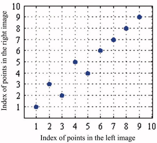
After manual analysis, the correct matching relations of the nine markers on these three surgical instruments can be obtained, as shown in . The corresponding relations of the points in are regarded as the standard in this experiment.
Figure 6. Correct matching relations of all points.
The values of μij (i = 1, 2, … , 9; j = 1, 2, … , 9) can be obtained using EquationEquations (4)–(14) and are reported in . Given μ < μc=1.0×e−3, al1 in the left image and ar1 in the right originate from the same marker in , i.e. the points are a right match. After the comparative analysis of all the points, the matching relations of the other markers are found to be correct.
Table 4. Values of μ of points in pairs of images.
However, pseudo markers still exist in practical applications. Thus, a board with 15 markers is designed in the experiment, as shown in .
Figure 7. Board with 15 markers: (A) markers captured by the near-infrared camera; (B) the geometry of markers.
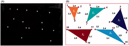
As shown in , five surgical instruments Ii (i = 1, 2, …, 5) are simulated, resulting in 15 markers, which are represented by pi (i = 1, 2, …, 15). Each instrument consists of three markers, as shown in . The distances between two markers of these five instruments are each unique. To obtain these distances, we capture six pairs of images of the luminous panel. After manual analysis, we have obtained the matching relations of all the markers. Subsequently, all the distances between two markers are measured using the intrinsic and extrinsic parameters of the NOS. The results are shown in .
Table 5. Distances between two markers of five instruments (unit: mm).
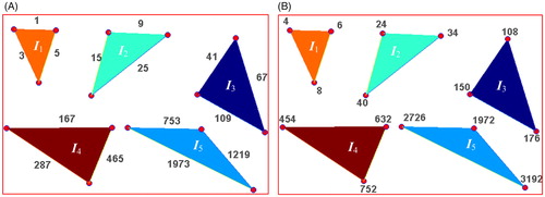
As shown in , the distances between two random markers on each instrument are unequal; thus, each distance can easily be distinguished with a unique code. According to EquationEquation (15)(15) , the distances (edges) of the five instruments are assigned codes, as shown in . The codes for the distances of the instruments are independent of the coding order of the surgical instruments. As shown in , the coding order of the instruments is from I1 to I5. Each marker is then given a code by summing the codes for the distances between the marker and the other two markers on the surgical instrument. The coding results for the markers are shown in .
Figure 8. Codes for surgical instruments: (A) codes for distances; (B) codes for markers.
The right and left images of the board were captured by the NOS. The subpixel coordinates of the 15 points in the pairs of images are extracted and shown in . After manual analysis, the matching relations of these 15 pairs of points are determined, as shown in , and regarded as the standard to verify the algorithm. After the subpixel coordinates of all the points in the pairs of images are obtained, we can derive the linear equations for the markers by using EquationEquations (4)–(12), and all the matching results satisfy EquationEquation (13)(13) , as shown in . However, given more than one marker exists on the same plane, 15 correct matches and 23 pseudo markers are derived among all the corresponding relations.
Figure 9. Matching results: (A) all matching results satisfying EquationEquation (13)(13) ; (B) experimental results.
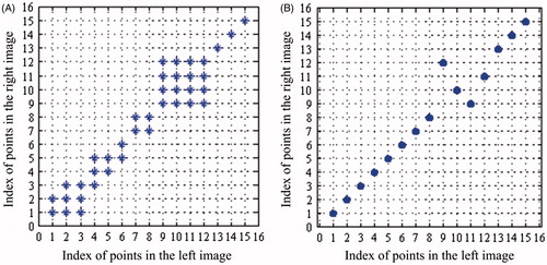
Table 6. Subpixel coordinates and matching relations of the 15 pairs of points.
An additional step of analyzing these 38 matching relations should be taken to identify the 15 correct matches by using the coding information of the surgical instruments. According to the distance codes and marker codes, we match the subpixel coordinates between the pairs of images. In EquationEquation (14)(14) , μ<μc=0.0001 and φ = 0.05 mm. Finally, we obtain the results, which are shown in . The comparative analysis results of the matching relations in and the results in show that the matching relations in the experiment are in accordance with the results in . Thus, the proposed algorithm is verified to be accurate in matching markers on multiple surgical instruments.
Conclusion
The near-infrared optical systems have been widely applied to surgical navigation. They perform a major function in clinical medicine. However, when multiple instruments are considered in an SNS, matching all the markers on the surgical instruments becomes a challenge. Thus, an effective, precise and rapid algorithm is necessary for stereo matching. This paper proposed a stereo matching and recognition algorithm using two intersecting lines and marker codes. The two intersecting lines could determine a point, and each marker code was the sum of the codes for the distances between the marker and the other two markers on a surgical instrument. To verify the algorithm, we conducted several stereo matching experiments on a single surgical instrument, multiple surgical instruments and multiple surgical instruments under a special condition. The experiment on a single instrument showed that the topological structure of its points in the pair of images were very distinct and could be correctly matched. Similarly, the experiment on three surgical instruments obtained good matching results. In both experiments, a one-to-one relationship existed. We also designed a board involving five surgical instruments for the third experiment. The experiment showed that one-to-one relationships did not exist between the subpixel points in the left and right images. To eliminate pseudo markers, we encoded the instruments by using the codes for the distances and markers. Finally, correct matching was achieved. Therefore, our algorithm can realize accurate matching of the markers on multiple surgical instruments and provide SNSs with precise positional information. Our future efforts will focus on improving the performance of the algorithm by clinical application.
Funding information
This research was funded by the State Scholarship Fund under Grant CSC No. 201408440326, the Pearl River S&T Nova Program of Guangzhou under Grant No. 2014J2200049 and No. 201506010035, the Project of Outstanding Young Teachers' Training in Colleges and Universities of Guangdong under Grant No. YQ2015091, the Features Innovative Program in Colleges and Universities of Guangdong under Grant No. 2015KTSCX069, the Guangdong Provincial Science and Technology Program under Grant No. 2013B090600057, No. 2014A020215006, the Fundamental Research Funds for the Central Universities under Grant No. 2014ZG003D.
Disclosure statement
The authors declare no conflict of interest in this study.
References
- Wu YY, Plakseychuk A, Shimada K. Computer-aided surgical planner for a new bone deformity correction device using axis-angle representation. Med Eng Phys. 2014;36:1536–1542.
- Sun S-P, Hsu H-C, Chou Y-J. Simulation of internal fixation surgery for calcaneal collapse with 3D full-sized computer-aided technology. Comput Aided Des Appl. 2012;9:599–607.
- Peterhans M, Oliveira T, Banz V, et al. Computer-assisted liver surgery: clinical applications and technological trends. Crit Rev Biomed Eng. 2012;40:199–220.
- Schiavone P, Boudou T, Ohayon J, et al. In vivo measurement of the human soft tissues constitutive laws. Applications to computer aided surgery. Comput Methods Biomech Biomed Eng. 2012;10:185–186.
- Georgii J, Eder M, Burger K, et al. A computational tool for preoperative breast augmentation planning in aesthetic plastic surgery. IEEE J Biomed Health Inform. 2014;18:907–919.
- Qian Y, Hui R, Gao X. 3D CBIR with sparse coding for image-guided neurosurgery. Signal Process. 2013;93:1673–1683.
- Meyer T, Kuc J, Uhlemann F, et al. Autostereoscopic 3D visualization and image processing system for neurosurgery. Biomed Tech. 2013;58:281–291.
- Oliveira-Santos T, Baumberger C, Constantinescu M, et al. 3D face reconstruction from 2D pictures: first results of a web-based computer aided system for aesthetic procedures. Ann Biomed Eng. 2013;41:952–966.
- Sun S-P, Hsu K-W, Chen J-S. Postoperative evaluation platform of female breast implant surgery with breast configuration indicator. Comput Biol Med. 2009;39:595–603.
- Ciocca L, Fantini M, de Crescenzio F, et al. CAD-CAM prosthetically guided bone regeneration using preformed titanium mesh for the reconstruction of atrophic maxillary arches. Comput Methods Biomech Biomed Eng. 2013;16:26–32.
- Subburaj K, Ravi B, Agarwal M. Computer-aided methods for assessing lower limb deformities in orthopaedic surgery planning. Comput Med Imaging Graph. 2010;34:277–288.
- Guignard J, Arnold A, Weisstanner C, et al. A bone-thickness map as a guide for bone-anchored port implantation surgery in the temporal bone. Materials. 2013;6:5291–5301.
- Fang T-Y, Wang P-C, Liu C-H, et al. Evaluation of a haptics-based virtual reality temporal bone simulator for anatomy and surgery training. Comput Methods Prog Bio. 2014;113:674–681.
- Cai K, Yang R, Ning H, et al. An automatic algorithm for distinguishing optical navigation markers used during surgery. Dyna. 2015;90:203–209.
- Taylor RH, Stoianovici D. Medical robotics in computer-integrated surgery. IEEE Trans Robot Automat. 2003;19:765–781.
- Tully S, Choset H. A filtering approach for image-guided surgery with a highly articulated surgical Snake Robot. IEEE Trans Biomed Eng. 2016;63:392–402.
- Wen R, Tay W-L, Nguyen BP, et al. Hand gesture guided robot-assisted surgery based on a direct augmented reality interface. Comput Meth Prog Biomed. 2014;116:68–80.
- Cai K, Yang R, Lin Q, et al. Near-infrared camera calibration for optical surgical navigation. J Med Syst. 2016;40:1–12.
- Lin Q, Yang R, Cai K, et al. Real-time automatic registration in optical surgical navigation. Infrared Phys Techn. 2016;76:375–385.
- Cai K, Yang R, Chen H, et al. Synchronization design and error analysis of near-infrared cameras in surgical navigation. J Med Syst. 2016;40:1–8.
- Zhang K, Sheng Y, Lv H. Stereo matching cost computation based on nonsubsampled contourlet transform. J Vis Commun Image Represent. 2015;26:275–283.
- Benedetti L, Corsini M, Cignoni P, et al. Color to gray conversions in the context of stereo matching algorithms: an analysis and comparison of current methods and an ad-hoc theoretically-motivated technique for image matching. Mach Vis Appl. 2012;23:327–348.
- Park M-G, Park J, Shin Y, et al. Stereo vision with image-guided structuredlight pattern matching. Electron Lett. 2015;51:238–239.
- Kang S, Hong H. Near-real-time stereo matching method using temporal and spatial propagation of reliable disparity. Opt Eng. 2014;53:063107.
- Kogler J, Eibensteiner F, Humenberger M, et al. Enhancement of sparse silicon retina-based stereo matching using belief propagation and two-stage postfiltering. J Electron Imag. 2014;23:043011.
- Wei Z, Ren L, Song S. Research on the 3-D reconstruction of industrial flame based on the ratio of controlled matching points. IJMUE. 2015;10:23–34.
- Liu J, Li C, Mei F, et al. 3D entity-based stereo matching with ground control points and joint second-order smoothness prior. Visual Comput. 2015;31:1253–1269.
- Zhou Z, Wu D, Zhu Z. Stereo matching using dynamic programming based on differential smoothing. Optik. 2016;127:2287–2293.
- Raghavendra U, Makkithaya K, Karunakar AK. Anchor-diagonal-based shape adaptive local support region for efficient stereo matching. Signal Image Video Process. 2015;9:893–901.
- Han W, Zheng J-B, Li X-X. A fast and accurate stereo matching algorithm based on epipolar line restriction. 2008 CISP'08 Congress on Image and Signal Processing, Sanya, China: IEEE; 2008:271–275.
- Donate A, Liu X, Collins EG. Efficient path-based stereo matching with subpixel accuracy. Syst Man Cybernet Part B Cybernet IEEE Trans. 2011;41:183–195.
- Wiles AD, Thompson DG, Frantz DD. Accuracy assessment and interpretation for optical tracking systems. Medical Imaging 2004, San Diego, CA: International Society for Optics and Photonics; 2004:421–432.