
Abstract
Background: Cardiovascular diseases are the first cause of death globally: an estimated 17.5 million people died in 2012. By combining the benefits of magnetic navigation and ultrasound (US) imaging, the authors proposed a robotic platform (i.e. the MicroVAST platform) for intravascular medical procedures.
Methods: A 3D imaging US-based tracking algorithm is implemented for the navigation of a magnetic-dragged soft-tethered device. Tests were performed to evaluate the algorithm in terms of tracking error and precision of locomotion.
Results: The 3D imaging US-based algorithm tracked the endovascular device with an error of 6.4 ± 2.8 pixels and a mean displacement between the endovascular device and the preoperative path of 13.6 ± 4.5 mm (computational time of 12.2 ± 1.5 ms and 30.7 ± 6.1 matched features).
Conclusions: The MicroVAST platform includes innovative solutions for navigation allowing for an assisted magnetic locomotion of medical devices in the cardiovascular district by combining a 3D imaging US-based tracking algorithm with pre-operative data.
Introduction
Cardiovascular diseases (CVDs) are the first cause of death globally. An estimated 17.5 million people died from CVDs in 2012, accounting for the 31% of all global deaths; of these deaths, the main causes are coronary heart disease (i.e. about 7.4 million) and stroke (i.e. about 6.7 million).[Citation1] Endovascular surgery and interventional radiology are minimally invasive medical methodologies performed introducing elongated and bendable radio-opaque instruments [Citation2,Citation3] in the vascular district for treating cardiovascular diseases. Actually, instruments guidance is performed under digital subtraction angiography (DSA) and fluoroscopy, with the periodic injection of contrast medium to visualize catheters and guidewires with respect to the vasculature.
Often the benefits offered by these catheter-based techniques, such as quicker recovery and decreased pain, cannot be obtained due to technical limitations to endoluminally reach the target area; for this reason, surgeons often choose to convert to a traditional open approach.
In an endovascular approach, the surgeon pushes the catheter along guidewires from outside the vascular access (being femoral artery the most frequent one), and the instrument intrinsic stiffness allows the propulsion of the entire instrument inside the patient.[Citation4] During the intervention, the surgeon often has to pass through some arterial bifurcations up to reach the area to treat. The surgeon rotates the instruments to steer their pre-curved tips up to achieve the correct orientation to enter in the right arterial branch. Different catheter and guidewires tip shapes have been developed to pass through different kinds of arteries bifurcations. Endovascular procedures require not only long training for the surgeons but also innate abilities. Those abilities are needed to choose, on-the-fly, the best strategy in terms of catheter shapes and movements to be performed. For these reasons, it is impossible to define a standardized procedure due to pathological and anatomical variations of any patient.
Mechanical and magnetic steerable catheters increase endoluminal device distal-end dexterity and maneuverability thanks to the possibility to change and bend, once required, the orientation of the tip.[Citation5–7] Nevertheless, since the instrument is still pushed from the proximal end, its propulsion remains sometimes impossible due to the friction resistance generated by the contact between a curved arterial wall and the straight instrument body.
Magnetic dragging from the distal side, for soft-tethered or completely wireless endoluminal devices, was proposed with the benefit of reaching areas often inaccessible for traditional vascular catheters and guidewires.[Citation8–13] However, these solutions are difficult to be applicable in the clinical practice. Some of them require dedicated room and MRI devices properly programmed to simultaneously drag and localize the surgical instruments, whereas some other solutions require external magnetic field emitters close to the patient able to drag the instruments but often too bulky to allow the traditional fluoroscopic or DSA guidance with X-ray emitter and receiver around the patient.
Many research groups in the world are working on medical robots and computer-assisted surgery (CAS) platforms for robotic vascular procedures [Citation14,Citation15] and also several US-based tracking systems for various types of targets have been introduced.[Citation16–18] Those systems are attractive for the treatment of cardiovascular diseases and they offer many possibilities for interaction and a high degree of accessibility. However, there are some challenges in the use of soft-tethered or completely wireless magnetic-driven endoluminal devices, such as (i) biocompatibility, (ii) possible damage of blood vessels, and (iii) control and navigation inside blood vessels especially against the blood flow that is one of the biggest challenges for those devices.[Citation19] This is a crucial point to be addressed in order to navigate the endoluminal device and to retrieve it (e.g. in case of a failed branch selection) as a safety measure.
In this paper, the authors propose a teleoperated robotic platform based on a traditional CAS scheme adapted to intravascular medical procedures and illustrated in . The robotic platform for vascular navigation is composed of three main modules: (i) a magnetic module for dragging a magnetic endovascular device in the patient body; (ii) a control module interfacing the magnetic module and the operator; and (iii) a module for processing the pre-operative data and the intra-operative data, these ones obtained from a US-imaging tracking system. One of the main benefits of this platform is the resulting non-invasiveness of the procedure for patients and for medical doctors, not exposed to ionizing radiation.
Figure 1. (a) Traditional CAS architecture adapted to intravascular medical procedures with magnetic dragging and US-based tracking. (b) The MicroVAST platform experimental setup for magnetic dragging of an endovascular device under US monitoring.
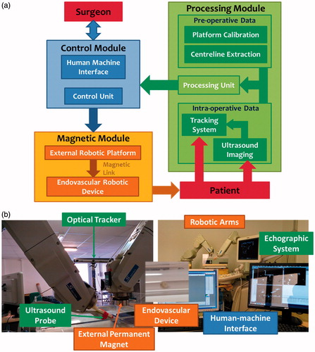
The teleoperated robotic platform for cardiovascular treatments developed by the authors [Citation20–22] employs a simple and compact external permanent magnet (EPM), for magnetic dragging, and a commercially available ultrasound (US) scanner, for tracking; EPM and US probe are moved together by two robotic manipulators (defined dragging and tracking robotic arms) along pre-determined vascular path (i.e. obtained in a pre-operative condition). The goal of this development is to reach areas often inaccessible for traditional vascular instruments through a soft-tethered magnetic-driven device under a non-invasive tracking modality. In particular, the platform combines the advantages of a magnetic dragged soft-tethered endovascular device with a low-invasive (no radiation, at all, to the patient and operators) real-time tracking based on 3D imaging US,[Citation23–25] thus making easier the integration in the clinical scenario. In a previous work, the authors implemented and tested a real-time tracking methodology based on 2D-imaging US for a soft-tethered magnetic-driven device. In particular, it was demonstrated that an image-based algorithm based on the combination of Shi–Tomasi features detector, Lucas–Kanade features tracking, and watershed segmentation technique represented the most reliable and accurate solution for the implementation of a tracking algorithm for endovascular magnetic instruments.[Citation26]
In this paper, the authors describe the integration of the processing and control module and investigate the implementation of a 3D imaging US-based tracking strategy able to accurately and reliably navigate a soft-tethered endoluminal device in the cardiovascular district.
The high-level strategy applies the algorithm, implemented and validated in a 2D-imaging configuration,[Citation26] to the three orthogonal US planes acquired by a 3D US machine. The expected benefit is that integrating the information from the other two 2D-imaging US orthogonal planes, together with the pre-operative path data, will improve the robustness and safety of the entire methodology.
The proposed analysis will compare the two different tracking pipelines (using one or three US-imaging planes) for continuously tracking a soft-tethered endovascular device, in order to assess which one is more suitable, safer, and accurate for integration in the MicroVAST endovascular CAS platform.
Materials and methods
MicroVAST platform: system overview and modules
The developed robotic platform, named MicroVAST, () comprises (i) one anthropomorphic robotic arm with six degrees-of-freedom (DoFs) (i.e. dragging robot; RV-3SB, Mitsubishi Electric, Tokyo, Japan) with an EPM attached to the end-effector; (ii) a second anthropomorphic robotic arm with six DoFs (i.e. tracking robot; RV-6SL, Mitsubishi Electric, Tokyo, Japan) for holding and moving a 3D imaging US transducer (X6-1, Philips Medical Systems, Bothell, WA); (iii) an optical tracker (Optotrak Certus, Northern Digital Inc., Waterloo, ON, Canada); (iv) a human–machine interface (HMI) including an intuitive control peripheral; and (v) a millimeter-size spherical-shaped capsule, embedding an internal permanent magnet (IPM). The interaction between the EPM and the IPM is used to propel the endoluminal device along the vascular tree. In particular, an axially magnetized NdFeB N52 (remanence 1.48 T) permanent magnet (K&J Magnetics, Jamison, PA) was selected as the EPM; it is 51 mm in diameter, 25 mm in thickness, and 0.4 kg in weight. A spherical-shaped capsule, 6 mm in diameter and 0.53 g in weight, was used as a prototype of the endovascular probe; it is worth mentioning that the approach can be scaled-down for fulfilling the medical requirements, still maintaining proper magnetic interactions for stable dragging. The endovascular device is equipped with a concentrically spherical NdFeB N42 magnet (IPM – K&J Magnetics, Jamison, PA) with a diameter of 4.7 mm. Further details about the magnetic interaction and CAS platform are available in the papers by Miloro et al. and Tognarelli et al.[Citation21,Citation22]
Navigation control architecture
The navigation control algorithm of the two robotic arms is designed to follow the patient vessel lumen path, which can be obtained preoperatively by elaborating the centerline from 3D imaging US or 3DRA images. In order to check that a reliable and effective magnetic link between the EPM and the endoluminal device is maintained along the entire procedure, the tracking robot holds and moves a US probe for real-time tracking; this is required for allowing accurate and reliable navigation (control scheme is reported in ). In particular, in order to obtain 3D real-time information – specification required for a reliable feedback for the entire control process – the authors employ a 3D imaging US system. In fact, a 3D imaging US probe can provide volumetric data or three orthogonal slices. Since real-time tracking using 3D US volumetric data can be difficult (due to technical limitations for real-time access and computational payload) and not always accessible on clinical machines,[Citation27] the authors decided to investigate a tracking strategy that exploits three orthogonal US planes for a flexible and online use of the algorithm on most clinically employed US 3D imaging machines.
Figure 2. Navigation control flow: the high-level strategy checks if the endovascular device is inside the SaW. If this condition is verified, the next positions in the pre-operative vascular path trajectory (T(K + 1)) are retrieved back to the robotic arms (P(K)). Otherwise only the previous position in trajectory (T(K − 1)) will be sent in order to re-establish a correct magnetic link. CoM stays for Center of Mass.
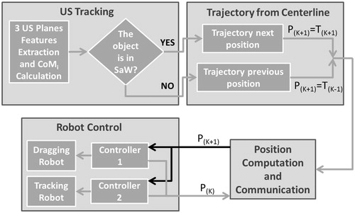
The US probe is moved by the tracking robot imposing that the intersection of the three orthogonal planes lies on the known vascular path. In particular, the two manipulators are moved together along the calculated pre-operative path. The aim of the high-level strategy is to maintain the endovascular device, which navigates along the centerline projection due to the magnetic attraction on the lumen wall, on the intersection of the US planes or, at least, inside an imposed safety window (SaW) centered in the US frame in each orthogonal plane. The movements of the two manipulators are driven by the output of the high-level strategy, i.e. if the endovascular device exceeds the imposed SaW in two orthogonal US planes, the procedure is retrieved to the previous state (T(K−1) in ) in order to maintain, or at least to re-establish, a reliable magnetic link (i.e. by placing back the device centre of mass – CoM – in the defined SaW).
In addition, the platform control unit and the software framework are suitable for developing an autonomous movement of the endovascular device along the vessel path. However, the operator can navigate the endoluminal device forward and backward along the lumen pre-operative vascular path due to a semi-autonomous and transparent computer-assisted control. A first implementation of the assisted navigation procedure has been achieved controlling the motion by using a haptic input device (Phantom-Omni, Sensable Technologies, Wilmington, MA).
The authors aim to track the endovascular device CoM on each US orthogonal plane by using a combination of computer vision methodologies in a specific tracking framework. In this paper, the entire platform control scheme, based on the locomotion of the two robotic arms and the tracking strategy of the endovascular device, is presented. In order to exhaustively describe the processing module of the MicroVAST platform, the following section will explain in detail the pre-operative (“Pre-operative module and settings: experimental test bench, system calibration and vessel centerline extraction” section) and the intra-operative modules (“Intra-operative module: 3D imaging US-based tracking algorithm implementation and assessment method” section) and respective subcomponents.
Pre-operative module and settings: experimental test bench, system calibration, and vessel centerline extraction
In the realization and setting of the overall robotic platform, several issues have been set and addressed, such as (i) experimental test bench, (ii) calibration of robotic arms and extrinsic calibration of the US probe, and (iii) extraction of the centerline from the experimental test bench. The following subparagraphs explain each issue in more details; it is worth mentioning that both calibration and vessel centerline extraction are performed before the medical intervention. The preoperative centerline path (recovered by the method presented in “Calibration of the robotic platform components” section) will be then registered, just before the procedure, with the real patient vascular anatomy obtained through a pre-procedural US-based scanning procedure of the target area.
Experimental test bench
The implemented 3D US-imaging tracking algorithm is evaluated in an in-vitro simulator that mimics the abdominal aorta dimensions. A 24-mm inner diameter PMMA tube was chosen in agreement with the physiological dimension of the abdominal aorta, ranging from 19 mm to 30 mm in diameter.[Citation28] On one hand, the in-vitro set-up presents intrinsic differences with respect to an ex-vivo or real in-vivo environment. In particular, the PMMA pipes are rigid and the path to be followed by the robotic device is simpler than in the real arterial tree. However, due the acoustic impedance of PMMA,[Citation29,Citation30] the US images result in low-quality images with respect to a real scenario. Nevertheless, a controlled condition, represented by rigid PMMA pipes, enables the achievement of a reliable analysis and assessment of the robotic platform, excluding the effects of an unpredictable deformable environment and resistance forces. On the other hand, to overcome those issues, test in an ex vivo conditions (i.e. a freshly excised porcine vessel) are carried-out for strengthening the validation of the tracking algorithms.
Calibration of the robotic platform components
A fundamental step for the platform setting is the definition of the position and orientation of all components (i.e. the two robotic arms, the EPM end-effector and the US probe). In particular, it is fundamental to know the relationship between the two robots and end-effectors, in order to move them coherently, and the relationship between the 3D imaging US volume and the entire robotic platform to track and drag the endovascular instrument. The calibration procedure was performed through an optical localizer (Optotrak Certus, Northern Digital Inc., Waterloo, ON, Canada). The rigid body transformations involved in the platform are depicted in .
Figure 3. (a) Schematic representation of the transformations involved in the robotic platform and in the calibrations procedures; (b) overlay of calculated transformations on the real images. Transformations represented by continuous lines are determined by direct measurement from the tracker, the robots controllers or the 3D US scanner. Dot lines represent transformations retrieved with calibration procedures, exploiting the direct measurement mentioned before.
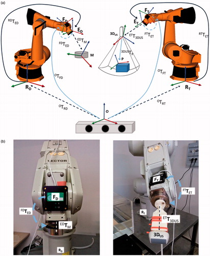
A closed-form calibration scheme was formulated in the calibration of each robot [Citation31] and was solved using a method based on Lie algebra,[Citation32] which allows us to determine the transformation between the reference systems of the robots and the optical localizer (OTRT for the tracking robot and OTRD for the dragging robot) and the spatial relationship between the reference systems of the optical sensor frames and the end-effectors (FTTET for the tracking robot and FDTED for the dragging robot). The calculation of the rigid body transformation between the dragging robot end-effector and the magnet EDTM was mechanically performed (i.e. through CAD model).
Moreover, in order to determine the transformation between the tracking robot end-effector and the 3D imaging US reference system ETT3DUS, the authors employed a closed form calibration scheme,[Citation33] exploiting a steady calibration phantom 3DUSTP.[Citation34,Citation35] Then, the transformation ETT3DUS was calculated employing the same algorithm used for the calibration of the robots. The calibration errors of each component of the robotic platform will be represented by means of the root-mean-square errors (RMSEs) and the maximum platform error will be derived by a bound error analysis.[Citation36]
Extraction of the vessel centerline
The vessel centerline represents the 3D path that has to be followed by the endovascular magnetic device. Due to magnetic attraction, the pre-operative vascular path will be represented by the projection of the extracted vessel centerline on the lumen wall, when the diameter of the vessel is larger than the endoluminal device dimension; otherwise, when the diameter of the endoluminal device and vessel are comparable in size, the vessel centerline will coincide with the path to follow. The vessel centerline can be pre-operatively determined with different imaging devices; in this specific case, US imaging was exploited. It is worth mentioning that one of the main benefits of the proposed platform is related to the non-invasiveness of the procedure, for patient and medical doctor. Therefore, US–US imaging registration (US images obtained with a robotic-assisted and localized 3D US probe for reconstruction and mono-modal alignment) of the pre-operative vascular path will be performed just before the medical procedure, in the real operating scenario.
Since the 3D US probe permits to acquire only small volumes at a time, the extraction of the entire path is not possible with a single acquisition. To acquire a volume covering the entire phantom, a panoramic reconstruction algorithm has been performed. Indeed, the 3D imaging US probe is moved by means of the robot in order to associate a position and orientation to the US volumes that are then merged to extend the scanner volume. Knowing the transformations ETT3DUS and RTTET, it is possible to infer the position and the orientation of each US volume in the tracking robot reference frame RT, and then the partial volumes are coherently combined into an extended and merged volume using, for instance, the reconstruction algorithm described in Ref.[Citation37] Once the volume was reconstructed, the centerline can be manually or automatically extracted (e.g. using an automatic algorithm as proposed by Zhang et al.[Citation27]) and refereed to the tracking robot reference system, RT. In the case of a US-based pre-operative extraction of the centerline, the procedure can be executed just before the intervention (no registration with the pre-operative virtual model is required in that case) and re-performed, if needed, during the medical procedure in a pre-procedural condition. Due to patient movement (e.g. breathing and/or other physiological movements), the vascular path can be different to the pre-operative virtual model and, therefore, the navigation of the two robotic manipulators has to be adjusted accordingly. This position and orientation adjustment (i.e. registration of deformable environments) can be performed exploiting, as registration references, the intraoperative vessel’s walls features obtained by the 3D US probe; in this case, several control reference points will be exploited to adjust the preoperative path with a reliable and dynamic superimposition process.[Citation27]
Intra-operative module: 3D imaging US-based tracking algorithm implementation and assessment method
In order to control and monitor the position of the endovascular device, a dedicated tracking algorithm was implemented. In order to obtaining the lowest invasiveness for physician and patient, a 3D imaging US-based technique was developed. The follow subparagraphs explain in detail the design choices for the intra-operative module (“US-based tracking algorithm: computer vision methodology” section and “US-based tracking algorithm: implementation on three orthogonal planes” section). Then, the methodologies employed for evaluating the algorithm in a controlled environment (i.e. in vitro tests) and also in a more realistic test bench (i.e. ex vivo tests) are described (“US-based three orthogonal planes tracking algorithm: experimental method” section).
US-based tracking algorithm: computer vision methodology
A US computer vision methodology, based on a combination of features extraction and matching, optical flow and segmentation, was implemented in order to obtain the most accurate and reliable results in terms of (i) number of detected and matched features extracted by the US images; (ii) accuracy/precision of the device CoM calculation (figured out as the CoM tracking error); and (iii) algorithm computational time. Several approaches, which differ for the extraction and matching methodology of features, have been implemented and compared with to understand which one fits better in the magnetic dragging of a soft-tethered device under US monitoring. A deep discussion on the different implemented algorithms is reported in Ref.[Citation26]; the most accurate and reliable algorithm, tested on a 2D US-imaging dataset, was a combination of a Shi–Tomasi features extractor, Lucas–Kanade features tracking and watershed segmentation technique.
As already mentioned, on-line tracking exploiting 3D US volumetric data can be difficult due to technical limits, such as real-time high-frequency access to the volumetric data and computational payload. For these reasons, a tracking algorithm that extracts the information of the endovascular device CoM from three orthogonal US planes will be integrated in the MicroVAST platform. In particular, the US probe, together with the magnetic source, will be moved imposing that the intersection of the three orthogonal US planes will lie on the projection of the known vessel centerline (i.e. pre-operative vascular path) on the lumen wall due to the magnetic attraction.
In the previous implementation [Citation26], the tracking algorithm exploited the information derived by a single US-imaging plane. This tracking algorithm required a first initialization phase in which the operator selects the endovascular device onto a region of interest (RoI) to start the tracking procedure. After this initialization, the endoluminal device is continuously tracked providing the endoluminal device CoM position to the dragging manipulator for autonomous navigation along the vascular path. The endoluminal device traveled the entire path, but in some operating conditions (mainly in concurrence with bifurcations), the tracking algorithm had to be restarted for the disappearance of the capsule in the US plane. For these reasons, integrating the information from the other two US orthogonal planes into the US-based control loop (imposing that the intersection of the three orthogonal US planes lies on the known vessel pre-operative path) is expected to improve the robustness and safety of the entire methodology. In accordance to our hypothesis, a previous study on various manual procedures (i.e. bead-in-hole navigation, bead-to-bead navigation, and tool-tip tracking) demonstrated that 3D imaging US can guide surgical tasks more efficiently and accurately than 2D US imaging.[Citation25]
A crucial point, described in the next sections, is to understand if the algorithm properly behaves in each of the three US planes, in order to use the information for all the US planes. This is important due to the different manner the US images are retrieved from the 3D US probe. In our case, keeping in mind the representation of due the hardware and firmware constraint of the 3D US probe used, the US images from plane 0 and plane 2 are retrieved as in a classic 2D US probe, meanwhile the US image from plane 1 is constructed (by the US machine) interpolating the other 2 US-imaging planes. The three US-imaging planes are then acquired by using a frame grabber (DVI2USB 3.0™, Epiphan, Ottawa, ON, Canada) and sent to the tracking algorithm.
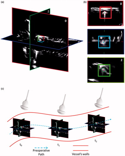
Figure 4. The high-level strategy running on the three US planes (i.e. 0, 1, and 2). The SaW is centered on the intersection of the three US planes (a). For a better visualization, an enlargement of each tracked plane and its respective SaW is showed in (b). (c) Scheme of the position of the three US planes in respect of the preoperative path and the relative position of the US probe. For a matter of clarity, in this figure, the preoperative path coincides with the vessel centerline as in the case of the diameter of the endoluminal device and the diameter of the vessel are comparable in size.
US-based tracking algorithm: implementation on three orthogonal planes
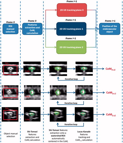
In order to implement the three orthogonal planes US tracking algorithm and evaluate the information provided by the other two US orthogonal planes, a dedicated multithreading software was developed and implemented; this allows us to elaborate, in the same computational cycle, the tracking information retrieved from the three US planes without a loss of performances. The implemented algorithm starts when the user selects the object from the three US planes by simply clicking on it (). The software exploits the user’s selected points as initial CoM, then three RoIs are expanded from them and specific features of the object are extracted. The actual CoM (i.e. CoMi) of the object is calculated as the algebraic mean of the positions of the features in the actual frame (frame i). After this phase, an adaptive dynamic RoI is centered on the previously calculated CoMi, inside which the algorithm extracts new characteristic features of the object. The features, previously extracted in frame i, are then found out in frame i+1, using a Lucas–Kanade optical flow, and the CoMi+1 is calculated. This loop is iterated until the end of the procedure. The adaptive dynamic RoI was implemented, using a watershed segmentation, for minimizing the area comprising the background, and essentially enclosing the object to be tracked. The watershed segmentation uses the previous CoM as its initial seed, while the maximum radius of expansion was set equal to 55 pixels (approximately equal to the endoluminal device dimension, set by a dedicated pilot study).
Figure 5. The multi-threading structure of the US tracking algorithm. In the lower part of the image, screenshot of the phases of the algorithm are reported. From each US plane, a 2D CoM position (i.e. plane 0 CoM(x,y), plane 1 CoM(x,z), and plane 2 CoM(z,y)) is obtained and it will be combined with the other components to obtain the 3D CoM position of the endovascular object.
The dragging and tracking manipulators are moved together along a calculated pre-operative vascular path, obtained by 3D US images, as explained in the “Extraction of the vessel centerline” section. A high-level strategy has been implemented to compare the position of the endoluminal robot CoMs, in each of the orthogonal US planes, with respect to three independent SaWs: from each plane, the 2D CoM position on the relative axes is calculated (). If the positions of the CoMs exceed the imposed safe limits (SaW red, blue and green boxes for each axes – ), the manipulators are stopped and retrieved in the previous position (i.e. “safe position”) in order to maintain or, in case, re-establish a reliable magnetic link and control.
US-based three orthogonal planes tracking algorithm: experimental method
In order to evaluate the effectiveness of the algorithm, a dedicated routine was implemented and applied on an off-line video in order to compute (i) the number of matched features, (ii) the CoM tracking error for the endoluminal device, and (iii) the computational time for each control loop. The procedure is performed and the off-line video is processed for analyzing the performance of the implemented algorithm and carrying out the different calculations. The off-line video consists of a forward and a backward magnetic navigation of the endovascular device along a 150 mm long straight path in a controlled condition (PMMA tube, 30.5 mm external diameter and 24 mm internal diameter). The navigation was iterated by dragging the device forward and backward along the path 50 times, in order to evaluate the reliability and robustness of the algorithm; no other aspects are affecting the test, such as friction and magnetic attraction dependability. The off-line video was recorded moving together the dragging and tracking manipulators along a calculated pre-operative vascular path obtained by 3D US images. In order to impose the locomotion of the endovascular device following exactly the movement of the EPM, the distance between the EPM and the endovascular device has been minimized (i.e. about 10 mm). This solution avoids the dependence of the effects of the magnetic field on the system locomotion behavior.
Furthermore, to evaluate the accuracy and reliability of the locomotion strategy of the endovascular device with respect to the extracted pre-operative path, a similar test (using the previously described plastic phantom, but with different operating conditions) was performed. This test is based on the knowledge that the intersection of the three orthogonal US planes lays exactly on the pre-operative vascular path (i.e. the vessel centerline, projected on the lumen wall). Using this information, it is possible to calculate the distance between the center of each plane and the CoM of the endovascular device for understanding how precisely the endovascular device can follow the pre-operative path in a real (even if simplified) condition that takes into account the presence of friction and magnetic gradients dependability, CoM tracking error and platform robotic calibration errors. From each US plane, a 2D CoM position is obtained (i.e. plane 0 CoM(x,y), plane 1 CoM(x,z), and plane 2 CoM(z,y)). Then the distance for each coordinate retrieved by the two corresponding planes (e.g. dCoM X from plane 0 and plane 1) and the mean for each coordinate were calculated (i.e. mean dCoM X as ((dCoM X plane 0) + (dCoM X plane 1))/2). This was done because, due to the noise in the images and tracking error, the coordinate retrieved from the two corresponding planes is not exactly the same. Finally, using the mean distance from each coordinate, the 3D distance from the pre-operative vascular path was calculated, as
In this evaluation phase, the distance between EPM and endovascular device has been set equal to 150 mm, considered it as an operating distance compatible with most of the procedures in normal subject. The results of the in vitro tests are reported in “In vitro test bench: evaluation of the US-based three orthogonal planes tracking performances” section and “In vitro test bench: evaluation of the precision of the locomotion of the endovascular device” section.
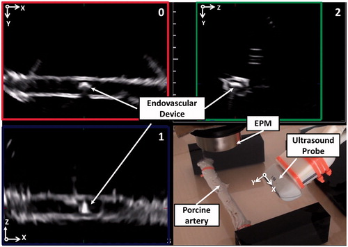
After the in vitro evaluation phase, the analysis of the number of the detected and matched features, the CoM tracking error and the computational time were repeated using a freshly excised porcine vessel (an inner diameter of 15 mm and a thickness approximately of 3 mm) instead of the PMMA plexiglass tube. The ex vivo test follows the same procedures as the in vitro tests but it is performed in a different environment (porcine vessel) that includes a lot of uncertainties compared to the plexiglass tube (variable friction, deformable walls, etc.). The ex vivo test bench is presented in . The precision of the locomotion of the endovascular device with respect to the extracted pre-operative vascular path was also evaluated in the ex vivo environment. The collected data are presented by showing mean and standard deviation of each component (i.e. number of matched features, CoM tracking error, computational time, and precision of the locomotion of the endovascular device). The results of the ex vivo tests are reported in “Ex vivo test bench: evaluation of the US-based three orthogonal planes tracking performances” section and “Ex-vivo test bench: evaluation of the precision of the locomotion of the endovascular device” section.
Figure 6. Ex vivo test bench and US images (planes 0, 1, and 2). The ex vivo tissue is submerged in water in order to guarantee a correct acoustic coupling for US imaging.
Results
Accuracy of the computer-assisted platform: robotic manipulator and US calibration
The calibration procedure introduces errors that have to be considered for the assessment of the overall accuracy of the platform. The RMSEs associated to the calibration of the two robots are 1.31 ± 0.35 mm and 1.31 ± 0.24 mm. The RMSE introduced by the US probe calibration is 3.88 ± 1.91 mm. The maximum error (worst case) derived by a bound error analysis is, therefore, 6.50 mm.[Citation36] Based on the knowledge of these data, all vessels, areas, and bifurcations with a typical size larger than 6.50 mm are feasible candidate for the applicability of the platform. Accuracy will be improved investigating different calibration algorithms, but it is worth mentioning that this aspect is out of the scope of the study, which is aimed at demonstrating the effectiveness of the US-based tracking and navigation strategy.
US-based three orthogonal planes tracking
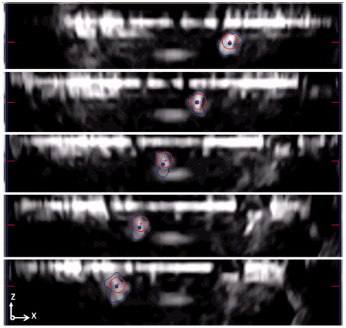
The US-based tracking algorithm was evaluated in two different ways. The first test was aimed at assessing the US-based tracking algorithm performance in terms of (i) the number of matched features, (ii) CoM tracking error, and (iii) computational time for each control loop. The CoM tracking error was derived as the difference between the center of a circle-shaped geometry constantly overlaid on the object frame and the CoM automatically calculated by the algorithm (red crosses and blue points as reported in ). As previously mentioned, from each US plane is retrieved a 2D CoM position (i.e. plane 0 CoM(x,y), plane 1 CoM(x,z), and plane 2 CoM(z,y)). In each plane, the distance between the CoM and the center of a circle-shaped geometry for each coordinate and the relative mean is calculated. The overall 3D CoM tracking error is then obtained using the mean CoM tracking error from each coordinate calculated as ).
Figure 7. Tracking error calculation as a difference of the circle CoM (red crosses) and the CoM calculated from the algorithms (blue points). In this evaluation stage, the endovascular device is moved back and forward along the path. The CoM tracking error is reported in the image for three different subsequent timings. For a clearer visualization, only the US plane 1 is showed in figure.
This evaluation stage considers that the algorithm has to be able to detect and match high numbers of features for the entire procedure, with the lowest CoM tracking error and the lowest, or at least compatible, time for an on-line processing control (the processing cycle has to be faster than the image frame rate, i.e. 25 Hz).
The second test was aimed to evaluate the locomotion of the endovascular device with respect to the extracted pre-operative vascular path. Both tests (i.e. evaluation of the performance and evaluation of the locomotion precision) were performed in the in vitro and in the ex vivo conditions.
The mentioned tests were performed using a personal computer with an Intel® Core™ i5-2380P and 8GB of RAM. The US-based tracking algorithm was implemented in C++ exploiting multithreading programming.
In vitro test bench: evaluation of the US-based three orthogonal planes tracking performances
The 3D imaging US-based algorithm control loop is processed with an average time of 12.2 ± 1.5 ms (thanks to the multithread software design); an average number of 30.7 ± 6.1 features were extracted from the segmented endovascular robot from each plane and a CoM tracking error (eCoM) of 6.4 ± 2.8 pixel was obtained. The mean 3D eCoM is calculated as 3D distance on each sample (eComX means the CoM tracking error on the X direction). Regarding the processing time, the 2D and the 3D implementations do not show relevant differences in performance even if the images were retrieved from different US machines (CA430E, Esaote, Italy for the 2D and X6-1, Philips Medical Systems, Bothell, WA, for the 3D). Regarding the CoM tracking error, the 2D implementation was compared with plane 0. This was done because the plane, in which the 2D probe acquires the images, is the same as the plane 0 in the 3D US probe. From these data, a first benefit of using a 3D probe is assessed. In fact, using the 3D probe more spatial information than using only a 2D probe is retrieved, without a higher computational payload on the system exploiting the multithread software design. Detailed results for each single plane are reported in .
Table 1. Performances of the implemented algorithm in an in-vitro environment. Performances are reported in terms of mean value ± SD, for the number of matched features, CoM tracking error (pixel and millimetre), and computational time (millisecond).
In vitro test bench: evaluation of the precision of the locomotion of the endovascular device
In this test, the locomotion of the endovascular device was evaluated. Knowing that the intersection of the 3 US planes lies on the extracted path and using the information from the tracking algorithm, it is possible to extract the difference between the pre-operative vascular path and the position of the tracked endovascular device. This test takes into account the presence of friction, magnetic gradients, CoM tracking error, and platform robotic calibration errors (i.e. robots and US probe), thus giving us a more complete evaluation of the locomotion strategy. The mean position displacement between the endovascular device and the pre-operative path is 13.6 ± 4.5 mm (dCoM X means distance of the CoM from preoperative path in the X direction). Minimum and maximum displacements are 2.1 and 21.8 mm, respectively. Detailed results for each single plane are reported in . The largest error is found on the X direction (depicted in and ) that is the main direction of locomotion. This error is principally due to the magnetic attraction and the friction resistance between the capsule and the plexiglass tube of the simulator. The error on the X direction could eventually cause the disappearance of the endovascular device from plane 2. Without using planes 0 and 1, it is not possible to find the 3D position of the device, and only the X and Y directions could be monitored.
Table 2. Locomotion precision of the endovascular device with respect to the pre-operative vascular path. The largest error is in the ‘X’ direction that was the main direction of motion. This error is mainly due to the friction between the endovascular device and the plastic simulator.
Ex vivo test bench: evaluation of the US-based three orthogonal planes tracking performances
For the ex vivo porcine trial, an average number of 27.8 ± 3.4 features were extracted from the segmented endovascular robot from each plane, while the control loop is processed with an average time of 11.3 ± 2.1 ms (). Regarding the CoM tracking error, due to the flexible and deformable nature of ex vivo tissues (e.g. friction, different thickness of the artery, deformation of the vessel’s wall due magnetic attraction, etc.), it was not possible to employ a full automatic overlay of the circle-shaped geometry on the endovascular device. For these reasons, from the off-line video, distinctive video segments (for a total of 750 frames) where the circle-shaped geometry was exactly overlaid on the endovascular capsule, were selected. In that case, an overall 3D CoM tracking error of 6.1 ± 5.7 pixel was obtained. The data obtained with the in vitro and the ex vivo setups were processed using the analysis of variance (ANOVA) method. This analysis showed that the two environments did not show relevant differences for the performance of the implemented tracking algorithm highlighting the robustness of the tracking algorithm to the environment change.
Table 3. Performances of the implemented algorithm in the ex vivo environment. Performances are reported in terms of mean value ± SD, for the number of matched features, CoM tracking error (pixel and millimetre), and computational time (millisecond).
Ex vivo test bench: evaluation of the precision of the locomotion of the endovascular device
In this test, the locomotion of the endovascular device was evaluated. As previously mentioned, this test encloses all the possible sources of errors present in the procedure (e.g. variable friction, resistance forces, magnetic gradients, deformation of the tissue, CoM tracking error, and platform robotic calibration errors) giving us a more complete evaluation of the locomotion strategy. Results for the ex vivo environment demonstrate that the mean position displacement between the endovascular device and the pre-operative vascular path is 15.1 ± 6.6 mm. Minimum and maximum displacements are 1.5 and 23.2 mm, respectively.
Detailed results for each single plane are reported in . As in the in vitro environment, the largest error is found on the X direction that is the main direction of locomotion (13.8 ± 5.0 mm for in vitro and 11.3 ± 5.1 mm for the ex vivo). This error is mainly due to the non-rigid nature of the magnetic link, friction, and resistance forces between the capsule and the deformable ex vivo tissue. In the ex vivo environment, also the errors on the Y and Z directions (2.1 ± 1.2 and 3.5 ± 2.3 mm, respectively, for the in vitro test, and 5.6 ± 2.4 and 8.6 ± 5.2 mm, respectively, for the ex vivo test) are significant, due to the deformability of the tissue and the not perfect cylindrical shape of the artery.
Table 4. Locomotion precision of the endovascular device with respect to the pre-operative vascular path. The largest error is in the ‘X’ direction that was the main direction of motion. This error is mainly due to the friction between the endovascular device and the ex vivo tissue.
Discussions
In this paper, the authors describe the integration and testing of the Processing Module components of the MicroVAST robotic platform for allowing the propulsion and guidance of an endoluminal magnetic device in intravascular procedures. Magnetic navigation offers several advantages, such as endovascular instrument with soft-tethered bodies dragged from the proximal side. This allows reaching areas often inaccessible for traditional vascular catheters. On the other hand, magnetic dragging has to be accurately monitored due to the non-rigid link between the external and the internal magnetic sources. In order to address this problem, 3D imaging US was chosen since it is compatible with the robotic platform and does not employ dangerous radiations for patients and physicians. For a proper navigation, it is also essential to know the trajectory that the endoluminal device has to follow. For this reason, within the robotic platform, modules were integrated for the extraction of the vessel centerline and for performing the calibration of the various systems. This was done in order to know position and orientation of each platform components and to calculate the position to be fed back to robotic manipulators. The vessel centerline will be coherent with the path to follow when the diameter of the endoluminal device and vessel are comparable in size. In case of larger vessels, the navigation path will be calculated, such as the projection of the centerline on the vascular wall, in the side where the magnetic link is established. Another issue to consider is that, due to patient movement (e.g. breathing and other physiological movements), the vascular path can differ with respect to the pre-operative path definition and therefore the navigation of the two robotic manipulators has to be adjusted accordingly, on-the-fly. The adjustment of the pre-operative path could be performed exploiting the intraoperative vessel’s walls positions (or references) retrieved from the 3D US images; doing so, several control reference points (from the vessel’s walls positions) are obtained in order to adjust the preoperative path with a reliable and dynamic superimposition process.[Citation27] Both manipulators are moved together along a calculated pre-operative vascular path obtained preoperatively by 3D US images. The preoperative images could also be obtained using other imaging systems such as CT, MRI, and 3DRA.
Since real-time tracking using 3D US volumetric images can be difficult, due to technical limits for real-time access to the data and computational payload, the tracking algorithm exploits the knowledge of the endovascular device 2D CoM on three orthogonal US planes. For those reasons, in this study, a three-plane US-based tracking algorithm was implemented and tested.
Moreover, the high-level strategy applies the implemented tracking algorithm. The endovascular device position is defined by the 2D CoMs obtained through the tracking algorithm: if the positions of the 2D CoMs exceed the imposed safe limits (i.e. SaWs), the high-level strategy stops the procedure and retrieves the manipulators in the previous state in order to maintain or re-establish a reliable magnetic link, i.e. by repositioning the endovascular device 2D CoMs inside the SaW limits.
The algorithm, in in vitro conditions, was able to track the endoluminal device matching 30.7 ± 6.1 features in each plane, with a computational time of 12.2 ± 1.5 ms and an error for the endoluminal device CoM tracking of 6.4 ± 2.8 pixels. Although the 3D implementation has more data to elaborate (i.e. ×3), the performance of the 3D imaging US-based tracking compared with the 2D implementation is similar. The 3D algorithm, in an ex vivo environment, tracked the device by matching 27.8 ± 3.4 features in each plane, with a computational time of 11.3 ± 2.1 ms. An overall CoM tracking error of 6.1 ± 5.7 pixel was obtained in the ex vivo test. The results obtained with the in vitro and the ex vivo setups were compared using the ANOVA method, which indicated that the two environments did not affect the performance of the implemented tracking algorithm. This demonstrates the robustness of the implemented tracking algorithm in dealing with different environments.
After this evaluation, another test on the precision of locomotion was performed. This test aimed to giving us a more complete evaluation of the locomotion strategy applied to the MicroVAST platform, taking into account the presence of friction, resistance forces, magnetic gradients, CoM tracking error, and platform robotic calibration errors. The error relative to the preoperative path extraction is negligible.[Citation27] In the in vitro test bench, the mean position displacement between the endovascular device and the preoperative vessel path is 13.6 ± 4.5 mm. The largest error was found on the main direction of locomotion and it is principally due to the magnetic non-rigid link (between the endovascular device and the EPM) and to the friction between the capsule and the plexiglass tube of the simulator. Regarding the ex vivo test bench, the mean position displacement between the endovascular device and the preoperative vessel path was 15.1 ± 6.6 mm. During those tests, the endovascular device was always tracked by the 3D imaging US-based tracking algorithm. It is worth mentioning that the EPM has a radius of 25.5 mm so, even in the worst case, the endovascular device is always under the EPM, thus allowing a reliable and effective magnetic link. The mean position displacement could also be considered as an offset value in the direction of motion; in this prospective, the real locomotion error (assumed as the locomotion precision) will be related to the standard deviation. Moreover, in order to employ the high-level strategy in a more efficient way, an adaptive SaW could be implemented keeping into account the expected direction of motion of the endovascular device (i.e. by exploiting the information from the pre-operative vascular path), and allowing a larger displacement in that specific direction. Additionally, even the robotic platform calibration error contributes to the overall positioning error.
Moreover, knowing the 3D displacement of the endovascular device from the pre-operative path, another locomotion control loop could be implemented. This loop exploits the 3D displacement information of the endovascular device and, instead of retrieving the robot in the previous state (), it will control accordingly the tracking and dragging robot in order to minimize the displacement. This control loop could be a feasible alternative to the current implementation especially in case of unpredictable motion (e.g. sudden motion of the patient) and it will evaluate in further studies.
The main benefit in using a 3D US probe is related on the possibility to retrieve more spatial information than using only a 2D probe, especially in critical areas such as bifurcations, where it is essential to choose the proper branch to continue the medical procedure. The 3D imaging US-based tracking implementation was also aimed at not having a bigger computational payload that could affect the performance of the platform. The results show that, from a computational point of view, the 3D and 2D US tracking payload performance are similar, so using a 3D US probe seems the most reasonable yet practical choice. Another important point is that, in the case of disappearance of the endovascular device from one US plane, the 3D position of the device is obtained using the CoM data from the other two US planes. Nevertheless, the 3D US probe used in this study has a lower spatial resolution compared with the 2D US probe employed in Ref. [Citation26]; this means that metric errors are bigger (especially in plane 1). This issue is only related to the specific US probe: using a more spatial resolute 3D US hardware would mitigate this problem.
For what concern the preoperative module, the robotic arms calibration RMSEs are 1.31 ± 0.35 mm and 1.31 ± 0.24 mm; the calibration RMSE for the US probe is 3.88 ± 1.91 mm. In order to improve the overall platform accuracy, a different platform calibration procedure is needed in conjunction with a the miniaturization of the endovascular device (currently, it is 6 mm in diameter). Accuracy could be improved investigating different calibration algorithms (i.e. exploiting some iterative algorithm [Citation38]). It is worth mentioning that this aspect is out of the scope of the work, which is aimed at demonstrating the effectiveness of the non-invasive 3D US-based tracking and navigation procedure. Nevertheless, with the actual implementation, the MicroVAST platform could navigate from inside vessels, areas, and bifurcations with a typical size larger than 6.50 mm.
After all those evaluations, a rough estimation on the percentage of the locomotion error due to platform robotic calibration and CoM tracking error is given. For this estimation, the locomotion error (in the worst case) is assumed to be the sum of all the uncertainties due to the different modules of the MicroVAST platform, e.g. resistive forces, magnetic link/gradients, CoM tracking error, and platform robotic calibration errors (i.e. robots and extrinsic and intrinsic calibration of the ultrasound probe). The error due to the extraction of the preoperative vascular path is negligible.[Citation27] The percentage of locomotion error due to CoM tracking error and platform robotic calibration errors is calculated as In the in vitro environment, the percentage error due to CoM tracking error and platform robotic calibration is around 16.2% and 47.8%, respectively. In the ex vivo environment, the percentage error due to CoM tracking error and platform robotic calibration is around 16.5% and 43.0%, respectively. The percentage error due to CoM tracking error in the in vitro and ex vivo environment is similar highlighting, once again, the robustness of the tracking algorithm due to the environment change. Meanwhile, the error caused by the platform robotic calibration is substantial (47.8% and 43.0% for the in vitro and ex vivo, respectively). Therefore, from this rough evaluation, a reduction of the platform calibration error could significant improve the precision of the locomotion.
The here proposed MicroVAST platform includes some innovative solutions for navigation and, combining a 3D imaging US-based tracking system with pre-operative data, it allows for an assisted or autonomous locomotion of soft-tethered probes in cardiovascular procedures. The integration of the information from the three US orthogonal planes into the US-based control loop consistently improves the robustness and the safety of the entire methodology. It is worth mentioning that one of the main benefits of the proposed platform is related to the non-invasiveness of the procedure, both for patients and medical doctors.
In conclusion, this implementation could be considered a step towards to a real application of multifunctional and versatile robotic platforms for healthcare applications. Further developments and implementations will focus at testing the platform in more complex vascular pathways, miniaturizing the endovascular device, increasing the precision of the platform and improving even more the US-based tracking strategy (e.g. exploiting GPU acceleration and implementing an adaptive SaW).
Funding information
This work was supported partly by Fondazione Pisa in the framework of the MicroVAST (Microsystem for Vascular diagnostics and inTervention) project and partly by the European Commission in the framework of the European Community's Seventh Framework Programme (FP7/2007-2013) under grant agreement [611963] (FUTURA Project www.futuraproject.eu).
Acknowledgements
The authors wish to thank Mr A. Melani and Mr N. Funaro for their help, suggestions and support in the manufacturing process of the MicroVAST system and test benches.
Disclosure statement
The authors report that they have no conflicts of interest.
References
- WHO. World Health Organization. Cardiovascular diseases (CVDs) Fact sheet No 317 2015. Available from: http://www.who.int/mediacentre/factsheets/fs317/en/.
- Dotter CT, Judkins MP. Transluminal treatment of arteriosclerotic obstruction description of a new technic and a preliminary report of its application. Circulation. 1964;30:654–670.
- Seldinger SI. Catheter replacement of the needle in percutaneous arteriography: a new technique. Acta Radiologica [Old Series]. 1953;39:368–376.
- Bloss P, Rothe W, Wünsche P, et al. Investigations of the pushability behavior of cardiovascular angiographic catheters. Bio-Med Mater Eng. 2003;13:327–343.
- Sensei TM. Robotic Navigation System; [cited 2013 Sept 30]. Available from: http://www.hansenmedical.com/sensei.
- CorPath 200 System; [cited 2013 Sept 30]. Available from: http://www.corindus.com/products/CorPath200.aspx.
- Niobe TM Remote Controlled Magnetic Navigation System; [cited 2013 Sept 30]. Available from: http://www.stereotaxis.com/.
- Arcese L, Cherry A, Fruchard M, et al., editors. Optimal trajectory for a microrobot navigating in blood vessels. Engineering in Medicine and Biology Society (EMBC), 2010 Annual International Conference of the IEEE; 2010: IEEE.
- Martel S, Mohammadi M, Felfoul O, et al. Flagellated magnetotactic bacteria as controlled MRI-trackable propulsion and steering systems for medical nanorobots operating in the human microvasculature. Int J Robot Res. 2009;28:571–582.
- Choi J, Choi H, Cha K, et al., editors. Two-dimensional locomotive permanent magnet using electromagnetic actuation system with two pairs stationary coils. In: 2009 IEEE International Conference on Robotics and Biomimetics (ROBIO). New York: IEEE; 2009.
- Fountain TW, Kailat PV, Abbott JJ, editors. Wireless control of magnetic helical microrobots using a rotating-permanent-magnet manipulator. In: 2010 IEEE International Conference on Robotics and Automation (ICRA). New York: IEEE; 2010.
- Pan Q, Guo S, Okada T, editors. Development of a wireless hybrid microrobot for biomedical applications. In: 2010 IEEE/RSJ International Conference on Intelligent Robots and Systems (IROS). New York: IEEE; 2010.
- Yesin KB, Vollmers K, Nelson BJ. Modeling and control of untethered biomicrorobots in a fluidic environment using electromagnetic fields. Int J Robot Res. 2006;25:527–536.
- Nakamura S, Harada K, Sugita N, et al., editors. Electromagnetic drive of microrobot geometrically constrained in blood vessel. In: Engineering in Medicine and Biology Society, EMBC, 2011 Annual International Conference of the IEEE. New York: IEEE; 2011.
- Plotner P, Harada K, Sugita N, et al., editors. Theoretical analysis of magnetically propelled microrobots in the cardiovascular system. In: Engineering in Medicine and Biology Society (EMBC), 2014 36th Annual International Conference of the IEEE. New York: IEEE; 2014.
- Koizumi N, Funamoto T, Seo J, et al., editors. A novel robust template matching method to track and follow body targets for NIUTS. In: 2014 IEEE International Conference on Robotics and Automation (ICRA). New York: IEEE; 2014.
- Krupa A, Fichtinger G, Hager GD. Real-time motion stabilization with B-mode ultrasound using image speckle information and visual servoing. Int J Robotics Res. 2009;28:1334–1354.
- Abolmaesumi P, Salcudean SE, Zhu W-H, et al. Image-guided control of a robot for medical ultrasound. IEEE Trans Robotics Autom. 2002;18:11–23.
- Martel S. Microrobotics in the vascular network: present status and next challenges. J Micro-Bio Robot. 2013;8:41–52.
- Tognarelli S, Miloro P, Verbeni A, et al., editors. Low invasive therapy under robotic guidance in the vascular district: a case study. In: 3rd Joint Workshop on New Technologies for Computer/Robot Assisted Surgery; 2013: Proceeding of the Workshop on New Technologies for Computer/Robot Assisted Surgery.
- Miloro P, Llewellyn MK, Tognarelli S, et al., editors. An innovative platform for treatment of vascular obstructions: system design and preliminary results. In: 2012 4th IEEE RAS & EMBS International Conference on Biomedical Robotics and Biomechatronics (BioRob). New York: IEEE; 2012.
- Tognarelli S, Castelli V, Ciuti G, et al. Magnetic propulsion and ultrasound tracking of endovascular devices. J Robot Surg. 2012;6:5–12.
- Moore JT, Chu MW, Kiaii B, et al. A navigation platform for guidance of beating heart transapical mitral valve repair. IEEE Trans Bio-Med Eng. 2013;60:1034–1040.
- Lange T, Eulenstein S, Hünerbein M, et al. Augmenting intraoperative 3D ultrasound with preoperative models for navigation in liver surgery. In: Barillot C, Haynor D, Hellier P, editors. Medical image computing and computer-assisted intervention–MICCAI 2004. Lecture Notes in Computer Science, vol. 3217. Berlin, Heidelberg: Springer; 2004. p. 534–541.
- Cannon JW, Stoll JA, Salgo IS, et al. Real-time three-dimensional ultrasound for guiding surgical tasks. Comput Aided Surg. 2003;8:82–90.
- Mura M, Ciuti G, Ferrari V, et al. Ultrasound-based tracking strategy for endoluminal devices in cardiovascular surgery. Int J Med Robot Comput Assist Surg. 2015;11:319–330.
- Zhang L, Parrini S, Freschi C, et al. 3D ultrasound centerline tracking of abdominal vessels for endovascular navigation. Int J Comput Assist Radiol Surg. 2013:1–9.
- Erbel R, Eggebrecht H. Aortic dimensions and the risk of dissection. Heart. 2006;92:137–142.
- Bloomfield PE, Lo W-J, Lewin PA. Experimental study of the acoustical properties of polymers utilized to construct PVDF ultrasonic transducers and the acousto-electric properties of PVDF and P (VDF/TrFE) films. IEEE Trans Ultrason Ferroelectrics Freq Control. 2000;47:1397–1405.
- Goss S, Frizzell L, Dunn F. Ultrasonic absorption and attenuation in mammalian tissues. Ultrasound Med Biol. 1979;5:181–186.
- Freschi C, Troia E, Ferrari V, et al. Ultrasound guided robotic biopsy using augmented reality and human-robot cooperative control. In: Conference Proceedings: Annual International Conference of the IEEE Engineering in Medicine and Biology Society IEEE Engineering in Medicine and Biology Society Annual Conference. 2009;2009:5110-3.
- Martin: FPaB. Robot Sensor Calibration: Solving AX = XB on the Euclidean Group. IEEE Trans Robot Autom. 1994;10:117–721.
- Viswanathan A, Boctor EM, Taylor RH, et al., editors. Immediate ultrasound calibration with three poses and minimal image processing. Lecture Notes in Computer Science; 2004.
- Freschi C, Parrini S, Dinelli N, et al. Hybrid simulation using mixed reality for interventional ultrasound imaging training. Int J Comput Assist Radiol Surg. 2015;10:1109–1115.
- Lo Presti G, Freschi C, Sinceri S, et al. Virtual reality surgical navigation system for holmium laser enucleation of the prostate. Lecture Notes Comput Sci (including subseries Lecture Notes in Artificial Intelligence and Lecture Notes in Bioinformatics); 2014. p. 79–89.
- Kim HS, Choi YJ. The kinematic error bound analysis of the Stewart platform. J Robot Syst. 2000;17:63–73.
- Parrini S, Cutolo F, Freschi C, et al., editors. Augmented reality system for freehand guide of magnetic endovascular devices. Engineering in Medicine and Biology Society (EMBC), 2014 36th Annual International Conference of the IEEE. New York: IEEE; 2014.
- Strobl KH, Hirzinger G, editors. Optimal hand-eye calibration. In: 2006 IEEE/RSJ International Conference on Intelligent Robots and Systems. New York: IEEE; 2006.