
Abstract
Medical imaging techniques provide a wealth of information for surgical preparation, but it is still often the case that surgeons are examining three-dimensional pre-operative image data as a series of two-dimensional images. With recent advances in visual computing and interactive technologies, there is much opportunity to provide surgeons an ability to actively manipulate and interpret digital image data in a surgically meaningful way. This article describes the design and initial evaluation of a virtual surgical environment that supports patient-specific simulation of temporal bone surgery using pre-operative medical image data. Computational methods are presented that enable six degree-of-freedom haptic feedback during manipulation, and that simulate virtual dissection according to the mechanical principles of orthogonal cutting and abrasive wear. A highly efficient direct volume renderer simultaneously provides high-fidelity visual feedback during surgical manipulation of the virtual anatomy. The resulting virtual surgical environment was assessed by evaluating its ability to replicate findings in the operating room, using pre-operative imaging of the same patient. Correspondences between surgical exposure, anatomical features, and the locations of pathology were readily observed when comparing intra-operative video with the simulation, indicating the predictive ability of the virtual surgical environment.
Introduction
Current medical imaging techniques provide a wealth of information for surgical preparation. Routine use of computed tomography (CT) and magnetic resonance imaging (MRI) can provide surgeons with accurate, high resolution volumetric data on the geometry and relationships of tissues that impact the course of a surgical procedure. Both pathologic changes and normal anatomic variation can be identified, allowing the surgeon to construct a mental representation of what he or she expects to encounter at the time of the procedure, and modify techniques accordingly. The quality of imaging technology continues to improve, constantly providing additional valuable anatomic details over time.
Despite the tremendous progress in the quality of preoperative imaging, surgeons still continue to examine volumetric datasets in much the same manner as they’ve done since the advent of digital tomographic imaging over 40 years ago. Volumetric data are examined as a series of two-dimensional slices, which leaves the surgeon the challenge of reconstructing these to formulate an understanding of complex three-dimensional relationships. This process can be a considerable challenge for novice surgeons, and even experienced surgeons can be misled in complex cases. It would therefore seem that traditional methods fail to take full advantage of the inherent three-dimensional nature of these imaging modalities.
The use of three-dimensional reconstructions of clinical data has been used to address this issue.[Citation1,Citation2] Still, these attempts have been hindered by a lack of computational power and challenges in user interface design to allow surgeons the ability to manipulate complex datasets and interpret them in a surgically meaningful way. Recent advances in computational speed, graphical rendering, and haptic technology have enabled practical methods of real-time imaging manipulation in the clinical setting. As a result, surgeons have the potential to work directly with representations of their patients’ anatomy in a virtual setting prior to undertaking an actual surgical procedure.
Temporal bone and lateral skull base surgery provides a good model for the initial application of patient-specific surgical rehearsal. There is high anatomic complexity within the ear and skull base, with numerous interrelated vital structures within a small, confined space. There is a variety of pathology that requires surgical navigation through this area while avoiding injury to adjacent anatomy. Both naturally occurring variability and that resulting from pathology have great influence of the selection of a surgical approach. Anatomy is also rigidly fixed within the bony framework of the skull base, reducing the need to simulate soft tissue deformations. The procedures are also performed by a single surgeon, which simplifies the design of the immersive interface.
We present our work towards the creation of a virtual environment workstation for use in temporal bone and skull base surgery. Our objectives included the following:
To build a system that can robustly use routine clinical pre-operative studies from a variety of sources.
To allow clinicians the ability to construct simulation scenes, including the visual characteristics of various anatomic structures.
To render anatomy in real-time and from user-selected perspectives with sufficient realism to provide a surgeon with a recognizable representation of structures.
To provide the user with the capacity to remove volumes systematically to replicate approaches and exposure expected at the time of actual surgery.
To provide the user with the flexibility to easily save and modify virtual dissections to facilitate experimentation that may yield the development of an optimal plan.
This article is organized as follows. The remainder of this section discusses related work and establishes the context within which the contributions of our present work are situated. Section ‘Materials and Methods’ describes our virtual surgical environment and the visual and haptic rendering techniques we developed to enable its creation. Section ‘Results’ shows results from our initial assessment of the virtual surgical environment on a variety of temporal bone surgery cases. Implications of our findings and future prospects are discussed in the section ‘Discussion’.
Related work
Virtual reality-based simulation, complete with haptic feedback, has enjoyed a rich history within the discipline of otologic surgery. One of the earliest documented surgical simulators for virtual temporal bone dissection was developed by Wiet and his team at the Ohio State University.[Citation3,Citation4] The goal of this simulator was to provide a virtual temporal bone dissection experience with interactivity and realism comparable to working in a cadaver laboratory. Their system uses a model of the temporal bone anatomy derived from CT images of a cadaveric specimen, and employed volumetric rendering techniques both for visual and haptic feedback. The project is still active, with the simulation system having been improved continually over the years.[Citation5,Citation6] The OSU simulator is currently undergoing a multi-center evaluation, and its training efficacy has already been demonstrated to complement the use of standard cadaveric temporal bones.[Citation7]
Another temporal bone simulator of note is that developed by the team at the University Medical Center Hamburg-Eppendorf.[Citation8,Citation9] Their simulator also employs a volumetric representation of the temporal bone anatomy from which haptic and visual feedback is rendered. Thus far, it has been successfully commercialized as the VOXEL-MAN Tempo surgery simulator for the purposes of surgical training. Some results from an experiment to use individual models derived from patient-specific image data within this simulator were also reported in a recent article.[Citation10]
At around the same time, Agus and his colleagues at CRS4 in Italy were also developing a simulator for temporal bone surgery.[Citation11,Citation12] A defining characteristic of their simulator was that it emphasized haptic fidelity of the virtual bone dissection, using a physically based model for computing force feedback and bone erosion. The simulator was assessed qualitatively in a brief report.[Citation13]
Our own research group at Stanford University has been actively investigating simulation of temporal bone surgery beginning with the work of Morris and Sewell.[Citation14,Citation15] A unique quality of this surgical training system is that it was designed with an ability to automatically assess the performance of the user, providing capabilities for feedback and evaluation of the surgeon-in-training.[Citation16,Citation17] Since then, this system had been fully redesigned and retooled for patient-specific simulation using pre-operative image data, for the primary purpose of surgical rehearsal.[Citation18] Indeed, we may regard the present work as an extension and completion of our previous work which reported preliminary results.
For completeness, we note here two other known reports of temporal bone surgery simulation using a virtual environment. The first is the visible ear simulator [Citation19] developed by the Alexandra Institute in Denmark. It uses an anatomical model created from high-resolution cryosection images of a human temporal bone to achieve a very realistic visual effect. Although this simulator is less prevalent in the academic literature, it is one of the most polished and widely distributed temporal bone simulators, as it is available freely for download from the project web site. The final instance of related work of which we are aware is a new simulation project [Citation20] that, as of this writing, was recently started at the University of Manitoba in Canada.
Contributions
The defining characteristic of the virtual surgical environment presented in this paper is that it is designed principally to operate on patient-specific, pre-operative image data. Meaningful simulations of various aspects of a temporal bone procedure can be conducted directly on a clinical CT image. Computational methods were selected or devised to maximize the fidelity of the haptic and visual feedback within the simulation environment, given the nature of the pre-operative image data used.
In particular, this is the first simulator for temporal bone surgery to implement a full six degree-of-freedom haptic rendering process to convey both force and torque feedback. The method described can render multiple contacts on the body of the virtual instrument with very high stiffness directly from the input image data. Virtual bone dissection is simulated according to the physical processes of orthogonal cutting [Citation21] when using a cutting burr and two-body abrasive wear [Citation22] for a diamond burr. These processes have been studied formally and extensively in the context of machining (of metal and of various other materials, including bone [Citation23]), and we apply the learned theory to achieve high-fidelity force feedback during virtual bone dissection in the simulation environment.
A volume rendering engine based on the technique of ray casting [Citation24] was also developed to facilitate high-quality visual feedback during the simulation. The renderer accepts volumetric image data together with a mask (to facilitate dynamic tissue removal) and an optional label volume, and allows the shading of each segmented structure to be fine-tuned to approximate its real appearance. Surgical simulation is a real-time interactive application requiring fast visual refresh rates, and a number of key optimizations were applied to achieve high-definition visual feedback on a stereoscopic display using commercially available desktop computer systems.
The predictive ability of the virtual surgical environment is demonstrated by comparing findings within the simulator to intra-operative observations from the same patient’s procedure. Correspondences between surgical exposure, anatomical features, and the locations of pathology relative to adjacent structures can be readily observed between the intra-operative video and the simulation with that patient’s pre-operative image data within the virtual surgical environment. The ability to replicate these findings was continually assessed by our surgical team in an ongoing manner to help guide system development.
Materials and methods
The virtual surgical environment accepts a specific patient’s pre-operative imaging data in DICOM format as input, and will primarily render visual and haptic feedback from these images during the interactive simulation process. The modality, resolution, and imaging characteristics are determined clinically by what is needed for the planned procedure. The primary image series usually takes the form of a clinical CT scan of the head or temporal bone for the procedures we have studied. Optionally, one or more binary label volumes, for segmentations of relevant anatomical structures, can also be provided. These segmentations allow unique visual and haptic properties to be applied to specific structures which would not otherwise have a distinct appearance in the pre-operative image alone.
If available, the intra-operative video associated with each patient’s procedure can also be loaded and played back within the virtual surgical environment. This capability is most beneficial when the simulator is used in the context of surgical education, where a resident can, for instance, watch a recording of a procedure performed by the attending surgeon while reproducing the same on a virtual replica of the patient’s anatomy. In our case, the ability to work with the intra-operative videos greatly assisted with our development and fine-tuning of the virtual surgical environment, and enabled us to collect the results presented in this article.
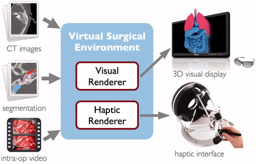
The software system consists of two primary components, as illustrated in . The visual renderer computes an interactive volume visualization of the image data and the surgical instruments, and can display the result on a variety of standard or commercially available stereoscopic 3D displays. The haptic renderer is responsible for computing force feedback during interaction with the virtual anatomy as well as simulating the process of tissue dissection when the surgical instrument is actuated. A number of commercially available haptic devices are supported by the software and can be used interchangeably with the system. The computational methods employed by the two subsystems are described in detail in the sections that follow.
Figure 1. Component overview of the virtual surgical environment.
Data collection
Pre-operative, and occasionally post-operative, image data from patients who underwent various forms of temporal bone and skull base surgery at the Stanford ENT Clinic were collected over a period of approximately 4 years. As interesting or noteworthy cases were presented, the pre-operative CT and MR image data were anonymized and archived into our growing library of simulation data. All images were acquired as part of the standard patient care protocol, and thus no modifications to existing protocols were required to perform our study. Most of the operating theaters in our facility are equipped with video recording capability directly on the surgical microscope, and when available, recorded videos were also archived with the image data.
As a result of this data collection process, our simulation library now consists of approximately 30 individual surgical cases. These cases represent a broad range of disease and surgically treated pathology, including tymanomastoid surgery for cholesteatoma or chronic otitis media, cochlear implantation for sensorineural hearing loss, plugging of the superior semicircular canal, and a variety of other procedures involving the resection of middle ear and temporal bone neoplasms. The image data include head and temporal bone CT studies from a variety of clinical scanners and cone beam CTs. In-plane resolution of these images varies between 0.125 mm and 0.43 mm, and slice spacing ranged from 0.125 mm to 1.0 mm.
A number of patients were also imaged with various MRI sequences as part of the pre-operative protocol. Although these images were not directly used for visual or haptic rendering within the virtual surgical environment, they were registered with the CT images to aid in the process of creating label volumes for soft tissue structures during data preparation where relevant.
Data preparation
A process of segmentation to create label volumes is not strictly necessary to use pre-operative image data in the virtual surgical environment. However, providing an explicit segmentation of some key anatomical structures in the image data can greatly improve the manner in which they can be visually and haptically displayed. Radiodensity (Hounsfield) values in the CT images alone are not sufficient to differentiate between many soft tissue structures. In particular, the facial nerve, chorda tympani, cochlea, semicircular canals, and sigmoid sinus all appear with very similar Hounsfield values, and thus benefit from having an explicit labeling. In the absence of such, these structures may only be recognizable by observing distinctive landmarks on the bony framework which encases them.
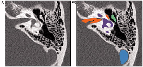
Segmentation of key structures relevant to temporal bone surgery was performed on several of the datasets collected for this study. Semi-automatic segmentation tools in the Amira 5 software package (FEI Visualization Sciences Group, Burlington, MA) were used to assist in this task, and the results of the segmentation for each structure were exported as binary label volumes with the same resolution as the original CT image (). The effort required for this process ranged from approximately one hour to one day of time for a technician or clinician familiar with the Amira software. The time requirement varied depending on the size of the CT image data, the completeness of the segmentation desired, the integration of CT and MRI data, and the user’s level of experience with the software.
Figure. 2. A slice of a CT image of the temporal bone (a), and corresponding slices of the label volumes superimposed onto the image (b). Labels are cranial nerves in orange, inner ear in purple, ossicles in green, and sigmoid sinus in blue.
Haptic rendering
If simulation technology is to be adopted into a clinical workflow, it is critical that the virtual surgical environment provide an interface that is intuitive and familiar for the surgeon. It became apparent early in our work that optimal exploration and manipulation of complex three-dimensional virtual anatomy was highly dependent on providing the user with the sense of touch. We also felt that a simulation should not allow unrealistic interactions between instruments and anatomy (for example, where the shaft of an instrument is able to pass through tissues). Such unrealistic interactions may encourage the adoption of maladaptive virtual surgical techniques that cannot be safely replicated in reality. Thus, haptic interaction should feel natural and realistic compared to the experience of working with a real temporal bone, at least to the extent possible given capabilities of the physical devices available.
We have developed a six degree-of-freedom haptic rendering algorithm to simulate the interaction between a rigid instrument and surfaces of anatomical structures that appear within volumetric medical image data. This method can render very stiff contact between hard tissue and any part of the user-controlled instrument while maintaining stable force feedback free from unwanted forces or vibrations. The algorithm is described briefly in this section, but we refer interested readers, particularly those with an intent to reproduce an implementation, to the original article describing this technique.[Citation25]
Data representation
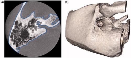
Objects we wish to touch and manipulate are those described by tissue boundaries within the pre-operative image data. Specifically, these are the surfaces of bone and some soft tissue structures that have been identified and segmented in the data. Tissue boundaries can often be captured by defining isosurfaces within the volume (), which divide the space into regions which exceed a certain radiodensity or intensity level (interior) and ones with lower intensities (exterior). These surfaces are defined directly on the pre-operative image data itself, rather than generated through a separate meshing or geometry processing stage. This reduces the computer memory storage requirements for the model and at the same time avoids geometric inaccuracies or loss of detail that may be introduced by a conversion of data representation.
Figure 3. A slice of a temporal bone image from a cone beam CT that shows the bone surface isocontour in blue (a) and the corresponding isosurface rendered in 3D (b).
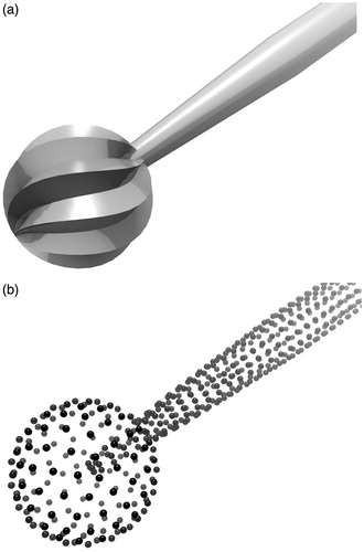
Isosurface geometries lend themselves to efficient query of point-object intersection tests. Thus, virtual instruments within the simulation are represented as point-sampled surfaces, or ‘point shells’,[Citation26] for the purpose of haptic rendering ().
Figure 4. A model of a cutting burr for visual rendering (a) and its corresponding point-sampled surface representation (b).
Collision detection
The goal of collision detection is to determine if or when the virtual instrument makes contact with the anatomical structures in the simulation as the instrument is moved about. With the chosen representations of the instrument and the anatomy, this interference test can be completed by querying each point of the instrument’s point shell for inclusion within a structure’s isosurface. However, if we wish to prevent interpenetrations between the virtual instrument and the scene geometry, a more sophisticated collision detection strategy must be employed.
Collision detection in our virtual environment considers the entire motion path between the previous known position of the instrument and the newly obtained position. Each point on the instrument’s body sweeps out a motion arc, which is subdivided into small intervals whose endpoints are iteratively tested for contact. Once an intersection is detected, interval bisection is used to efficiently refine the exact position of contact with the surface, to within a given numerical tolerance, thus allowing us to determine an intersection-free configuration of the instrument at the point of contact
Proxy motion simulation
Because haptic devices can only resist an operator’s motion with finite force, no haptic device is able to fully prevent the operator from physically pushing into a virtual object. A common practice to preserve simulation fidelity is to introduce a ‘proxy’ representation of the virtual instrument whose motion is independent from that of the haptic device manipulandum. The proxy represents an idealized configuration of the virtual instrument, and its role is to follow or track the position of the device manipulandum while subject to the constraint that it does not intersect the scene geometry. The goal of the haptic simulation is then to compute and update the configuration of the proxy at every time step as the device itself is moved.
The virtual instrument may be treated as a rigid body undergoing a motion specified by a generalized acceleration where
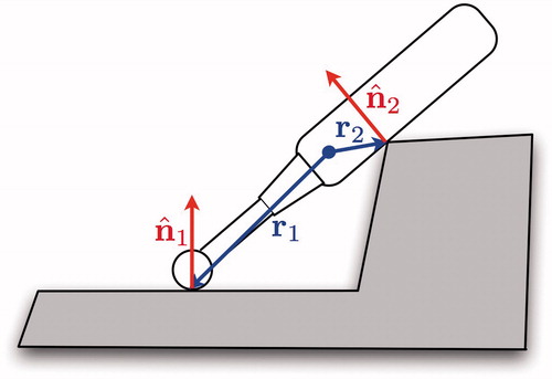
is the body’s linear acceleration and a→ is its angular acceleration. Then each contact induces a non-penetration constraint on the motion of the body in the form
where
is the unit normal of the contact and r is the position vector from the proxy’s coordinate frame origin (usually also its center of mass) to the contact position ().
Figure 5. Each point of contact on the instrument adds a non-penetration constraint of the form to the instrument’s motion.
One elegant solution to the proxy motion problem is provided by Gauss’ principle of least constraint. Of all allowable motions which satisfy the given constraints, Gauss’ principle states that the true (constrained) motion of the body will be the acceleration, ac , which minimizes the ‘acceleration energy’ or ‘kinetic distance’ [Citation27,Citation28]:
(1)
In the above, au is the unconstrained acceleration (i.e. the motion the body would take were there no contraints) and M is the inertia matrix of the body.
In the simulation, au is taken to be the acceleration that moves the proxy from its initial (previous) configuration to the target (device) configuration. The objective is then to minimize EquationEquation (1)(1) subject to the constraints Jc a ≥ 0, where the non-penetration constraint for each contact forms a row of the constraint matrix Jc. This amounts to a quadratic programming problem that can be solved with any of a variety of standard optimization algorithms. At every simulation time step, the proxy is moved according to the constrained acceleration obtained.
Virtual coupling
The final stage of the haptic rendering algorithm is to send a force (and torque) to the haptic device for display to the operator. This force is obtained by the simulation of a ‘virtual coupling’ [Citation29] spring, which generates a force proportional the displacement between the device position and proxy position, and a torque proportional to the difference in orientation between the two. If the proxy represents an ideal position for the virtual instrument, we can intuitively think of the virtual coupling as pair of springs (linear and torsional) which exert forces that attempt to pull the haptic device manipulandum, along with the operator’s hand, into alignment with the virtual instrument.
Simulation of bone dissection
The most important aspect of temporal bone surgery simulation is the ability for the surgeon to perform a dissection of the bone model using a virtual surgical drill. The drill has a high-speed spindle that drives a cutting or diamond burr on the end that mills away the bone tissue in a process similar to that of mechanical machining.
Many existing temporal bone simulators [Citation4,Citation8,Citation15] rely on an ad-hoc model for simulating the process of bone dissection. In such cases, non-physical parameters are adjusted to control the rate of bone material removal, which is often tuned to what an expert surgeon feels is reasonable for the procedure. A physically motivated model, if applied correctly during simulation, should yield a higher fidelity haptic experience of contact force and material removal. Agus et al. [Citation12] recognized this when they developed a temporal bone surgery simulator which computed and rendered haptic feedback based on Hertz’s contact theory and a work–energy argument for erosion of the bone material.
We believe that bone dissection with a cutting burr more closely resembles that of orthogonal cutting, and that dissection with a diamond burr can be described by abrasive wear. Orthogonal cutting refers to the process in which ‘the cutting tool generates a plane surface parallel to an original plane surface of the material being cut and is set with its cutting edge perpendicular to the direction of the relative motion of the tool and workpiece’.[Citation21] Recently, Arbabtafti et al. [Citation30] conducted an experiment to validate a model for cutting simulation based on Merchant’s derivations,[Citation21] and found measured forces during a controlled milling of bone to correlate well with theoretical predictions.
Previous physically based approaches [Citation12,Citation30] have relied on using a tool-tissue intersection volume to compute feedback forces and tissue removal amounts. The constraint-based haptic rendering algorithm we describe strictly enforces a non-intersection condition between the simulated virtual instrument and the bone geometry, which better reflects the situation in reality. However, it necessitates a bone dissection simulation approach that does not rely on an intersection volume. We describe here a physically based model for simulation of bone dissection, based on orthogonal cutting and abrasive wear theory, compatible with constraint-based haptic rendering.
Orthogonal cutting
A cutting burr on a surgical drill used for temporal bone surgery takes the shape of a fluted ball (). An axial cross-section of the cutting tool is shown in . As the drill spindle rotates the tool about its axis, the cutting edges of the flutes move tangentially to the plane of the bone surface, milling away a thin layer of the material.
Figure 6. A cutting burr (a) and a cross-sectional diagram showing how each flute of the burr engages the bone in orthogonal cutting (b).
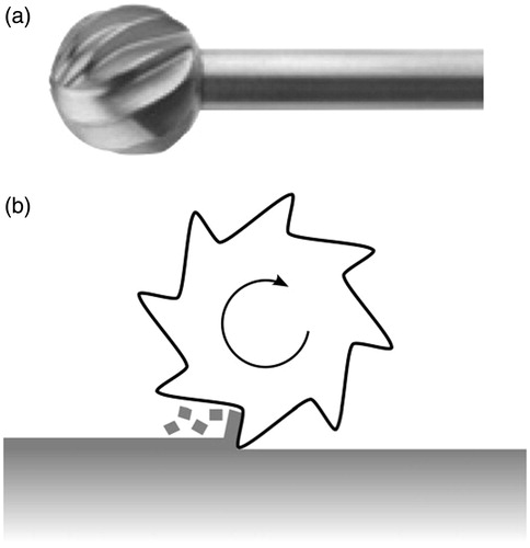
If we examine closely the geometry and the action of an individual cutting burr flute on the bone surface, we can see that it resembles the geometry of the orthogonal cutting process (). The cross-sectional diagram shows the cutting burr (tool) shearing off a bone chip from the surface of the bone tissue (work piece).
Figure 7. Geometry and forces associated with the orthogonal cutting process.
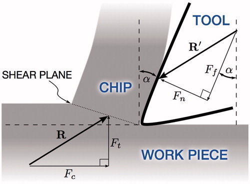
In Merchant’s derivation, the forces associated with the cutting process is revealed by considering the force system that holds the chip in stable equilibrium. The force exerted on the chip by the tool, R, is balanced by an equal and opposite force, R′, from the shearing and compression at the base of the chip. R can be resolved into perpendicular components Ft, the thrust force normal to the cutting plane, and Fc, the cutting force responsible for the total work done in cutting. Likewise, the rake angle of the tool, α, can be used to resolve R′ into a force Fn normal to the surface of the tool and a tangential force Ff.
Key relationships between the force quantities can be derived purely from the geometry of . We denote the magnitude of a vector as F = ‖‖ F ‖‖ to simplify the notation, with the direction of the vector implied by the diagram. In particular, the coefficient of friction between the bone chip and the tool surface can be expressed as
(2)
The specific cutting energy of the material, Wc, is the total work expended in cutting per unit volume of the material removed, and has units of Pa (N/m2), or equivalently J/m3. Its relation to the cutting force is
(3)
where Δ V is the volume of material removed and Δ x is the displacement of the tool along the cutting surface.
From the above equations, we can see that the physical quantities μ and Wc of the material can be calculated if the forces (namely Fc and Ft) and length quantities (chip thickness, chip width, and cutting velocity) can be observed during a cutting process. Indeed, orthogonal cutting theory was used by several researchers, including Wiggins and Malkin [Citation31] and Krause,[Citation32] to measure these quantities during a process of machining bone. Plaskos et al. [Citation33] used this model to conduct a similar experiment on bovine bone, but at the high speeds and shallow depths of cut typical for bone surgery, and found that the cutting energy increased under such conditions. This corroborates findings from Dillon et al. [Citation34], who measured forces encountered during controlled dissections of cadaver temporal bones, though they did not apply orthogonal machining theory in their analysis. Material properties used in our dissection simulation are calibrated to these results.
Abrasive wear
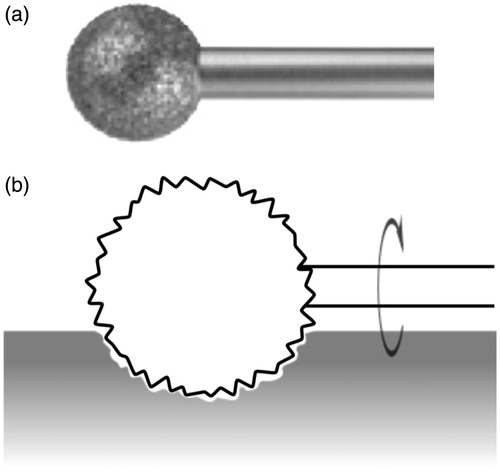
A diamond burr typically used in temporal bone surgery also takes the shape of a spherical ball, but is instead coated with diamond grit (). Two-body abrasive wear describes the process in which abrasive particles fixed to one body slide along the surface of the other body, thereby grinding away the softer material of the work piece. When in contact, the diamond particles on the rotating burr cut microscopic grooves in the bone to wear away the material.
Figure 8. A diamond burr (a) and diagram showing how the burr abrades the bone by cutting microscopic grooves at it rotates (b).
The rate of material removal during abrasive wear is governed by Archard’s well-known equation [Citation22]:
(4)
As before, Δ V indicates the volume of material removed for a relative displacement, Δx, between the two surfaces in contact. The applied load, or normal force, is denoted as Fn, and H indicates the Vickers hardness of the work piece. Finally, k is a dimensionless wear coefficient which encompasses additional physical and geometric properties including the coefficient of friction and the size of the abrasive particles.
During abrasive wear, we can see that the amount of the material removed is directly proportional to the applied force and the travel distance, and inversely proportional to the hardness of the material. The proportionality to force is consistent with observations made by Wu et al. [Citation35] to guide their development of a dental drill simulation. Although we’re not aware of other experiments validating abrasive wear theory for bone tissue, numerous results can be found for other materials. In a comprehensive series of experiments, Misra and Finnie [Citation36] verified the abrasive wear equation with a variety of abrasive particle sizes, using metals of different hardness, and sliding the contact at different speeds. They found typical values of the wear coefficient, k, to be in the range between 0.05 and 0.2, which primarily depended on the grit of the abrasive paper. Vickers hardness of human bone tissue was measured in an extensive study by Weaver [Citation37] and again verified with high precision in a recent study by Zysset et al. [Citation38]
Haptic simulation
The goal of our simulation is to generate high-fidelity force feedback during the virtual bone dissection process, in a manner compatible with constraint-based 6-DOF haptic rendering. We devised a novel simulation scheme with the general idea of computing the rate of material removal from the contact force and the physical properties of the material.
We first describe the case of orthogonal cutting using a cutting burr. When the virtual surgical drill is active, the contact force on the burr is exactly the thrust force, Ft. Rearranging EquationEquation (2)(2) gives us an expression for the cutting force in terms of the thrust force and rake angle:
(5)
Rewriting EquationEquation (3)(3) in terms of tangential velocity, the rate of material removal can be expressed as
(6)
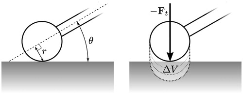
In the case of the spherical cutting burr driven by the spindle of the surgical drill, the tangential cutting velocity, ![]() can be expressed in terms of the radial distance to the spindle axis, r, and the spindle rotation speed, ω. The radial distance can further be expressed in terms of the burr radius, rb, and the orientation of the instrument with respect to the bone surface (, left), which yields
can be expressed in terms of the radial distance to the spindle axis, r, and the spindle rotation speed, ω. The radial distance can further be expressed in terms of the burr radius, rb, and the orientation of the instrument with respect to the bone surface (, left), which yields
(7)
Figure 9. Diagrams showing contact configuration parameters: radial distance to spindle axis r and drill orientation θ (left), thrust force Ft, and the iterative extrusion process in which the determined bone volume is removed (right).
Thus, we arrive at a final expression of the rate of removal of the bone material:
(8)
This equation describes the volume of cut material in terms of physical properties of the material (Wc and μ), geometry and configuration of the cutting instrument (α, rb, ω, and θ), and the applied force (Ft).
Likewise, for the case of dissection using a diamond burr, the abrasive wear equation can be used to find an expression for the rate of material removal. Since the applied load is equivalent to the thrust force in the previous case, Archard’s EquationEquation (4)(4) comes in a readily applied form:
(9)
Implementation
During virtual bone dissection, the simulation uses EquationEquations (8)(8) or (9), depending on the active burr type, to compute the theoretical amount of material removed (change in volume) during a given simulation time step. The geometry and spindle speed of the surgical drill determines the parameters α, rb, and ω. The physical properties Wc, μ, and H are taken from the material being removed, and can be adjusted individually for each tissue type present in the image data. The positions and orientations of the instrument proxy and haptic device determine θ and Ft. The wear coefficient, k, can be adjusted, if needed, to reflect the characteristics of the particular diamond burr being simulated.
After computing the change in volume, Δ V, for a time step, we can extrude the burr geometry in the direction of - Ft to form a cut region with volume equal to Δ V (, right). This region can then be cut from the mask image in an alias-free manner similar to that described by Pflesser et al. [Citation9] In practice, not all of the material within the cut region may be present. Thus, we perform this cutting step iteratively, expanding the extrusion by small amounts while sampling the image data until the cut region contains the calculated material volume.
Visual rendering
Visual appearance of the virtual anatomy is one of the most important aspects of a surgical simulator. In surgical rehearsal, a specific patient’s pre-operative image data serves to inform the surgeon what is to be expected at the time of surgery, and thus it is crucial that the visual rendering within the simulation remain readily recognizable when compared to the intraoperative view. For this reason, as with haptic rendering, visual feedback in our virtual surgical environment is rendered directly from the volumetric image data.
The visual renderer employs the general method of direct volume rendering [Citation39] which, in our case, is implemented on modern programmable graphics processors (GPUs) using a technique known as GPU-accelerated ray casting.[Citation40] This rendering strategy allows us to achieve high-quality visual output at truly interactive rates, even using inexpensive commodity computing hardware. Other simulators have employed a strategy of extracting and rendering surfaces within volume data, either explicitly via conversion a polygonal mesh [Citation15,Citation20] or implicitly using isosurface rendering,[Citation9,Citation41] to achieve faster rendering rates. However, translucency of the bone tissue provides a subtle, but important visual cue when exposing neurovascular structures (such as the facial nerve or sigmoid sinus) through thin layers of bone during surgery, which surface rendering methods fail to reproduce.
Visual appearance of the anatomy in our virtual surgical environment is controlled by the application of transfer functions that map image intensity values to visual properties including color, degree of transparency, and amount of specular reflection. We have provided a selection of pre-defined transfer functions for a variety of tissue types. These transfer functions can then be assigned and fine-tuned by the clinician or the scene technician within the simulation environment to either approximate the appearance of the real tissue, or to illustratively highlight specific or important anatomical structures, as desired.
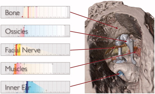
If a segmentation of the image data is provided, then a unique transfer function can be assigned to each labeled structure to give it a distinct appearance. Visual rendering of segmented data is accomplished in a manner similar to that described by Hadwiger et al. [Citation42] shows a rendering of segmented, non-clinical MicroCT image data with several transfer functions applied simultaneously to give structures distinct appearances.
Figure 10. Different transfer functions applied simultaneously in a volume rendering of a MicroCT image to give structures distinct appearances in the virtual surgical environment. For each segment, control points (colored circles) are used to define the shape and chromaticity of the transfer function. Radiodensity of the image is mapped to the horizontal axis and the vertical axis indicates relative opacity.
Unlike traditional volume visualization applications, a surgical simulation must provide a truly interactive experience, thus requiring the renderer to be highly efficient. Psychomotor and perceptual task performance within a virtual environment is noticeably impacted when the visual update rate falls below 15 Hz.[Citation43] The volume renderer in our virtual environment employs a number of select optimizations, including early ray termination,[Citation40] empty space skipping,[Citation44] and adaptive sampling, to run at fully interactive rates.
Then end result is a very efficient volume renderer that can generate high-quality images without compromising the appearance of fine anatomical structures, even at a high magnification. We have been able to achieve stereoscopic 3D renderings of high-resolution clinical CT scans (up to 512, × ,512, × ,480 image matrix) at full HD 1080p resolution with a 30 Hz refresh rate, using only commodity computer hardware.
Simulation workflow
The image data handling, haptic rendering, visual rendering, and simulation of bone dissection form the core components of our virtual surgical environment. When assembled together in a well-designed application for immersive simulation, these technologies enable the surgeon to do meaningful pre-operative planning and assessment of the patient-specific anatomy. We briefly describe the process through which a surgeon may use the virtual surgical environment for patient-specific simulation in this section.
The simulation workflow begins with the collection of pre-operative image data. A high-resolution clinical CT of the temporal bone is typically used as the primary imaging series from which the virtual representation of the patient’s anatomy is constructed. The virtual surgical environment can read the image series directly from DICOM format. Initially, a 3D reconstruction of the bone tissue is displayed (). Parameters can be adjusted to fine-tune the appearance of the model in the virtual environment as desired. If available, segmentations of additional structures, such as nerves, vasculature, or pathology, can also be added at this stage, and each assigned a unique haptic and visual appearance.
The virtual patient model can be oriented and placed within the virtual environment as desired by intuitive click-and-drag of the mouse. At this point, if a haptic device is available, the surgeon may begin a virtual dissection of the temporal bone. The haptic interface controls a virtual surgical drill with a selectable cutting or a diamond burr. Force feedback is rendered upon contact with the virtual anatomy during dissection, and the bone tissue is removed at a realistic rate dependent on the burr type and forces applied.
A full or partial dissection of the temporal bone can be saved to disk for later retrieval. Loading a saved dissection restores the model and the viewpoint to the recorded state. In addition, the virtual surgical environment provides an ‘undo’ and ‘redo’ capability. The simulation automatically records the state of the model whenever the drill is switched from on to off, and at any time during the virtual dissection, the surgeon may progressively revert the model to any of the automatically recorded stages of the dissection. Combined, these capabilities greatly encourage the surgeon to experiment with different approaches on the virtual anatomy. This is important because the familiarity and understanding of the patient’s particular anatomy and pathology that the surgeon acquires while working with the model is precisely what patient-specific simulation attempts to achieve.
Finally, the entire virtual surgical scene, including the position of the surgical microscope (camera) and patient model, the appearance of each structure within the model, and the state of the dissection, can be saved to disk and restored exactly at a later time. These simulation cases may be transferred between different computer systems that run the virtual surgical environment. This permits easy archival of specific patient cases, which can lead to a variety of beneficial uses. For example, cases with anatomy or pathology which present specific challenges for surgical technique can be archived to form a library for future training. Recorded virtual dissections on patient-specific anatomy can also serve as a vehicle for communicating surgical plans between clinicians.
Results
The primary goal of our present work, with respect to assessment, was to evaluate the ability of the virtual surgical environment to use pre-operative image data to replicate findings in the operating room with the same patient. Conducting a retrospective evaluation, where we first collected video and image data for a patient who underwent surgery and then examined the case within the simulation environment, allowed us to assess the virtual surgical environment without affecting the actual operative care process in any way. After assembling the cases, we asked surgeons and trainees within our team to reproduce key stages of the procedures within the simulation environment by observing and following the procedure as it was performed on the actual patient and recorded in the intra-operative video. Observations and results from a selected variety of cases are shown in this section.
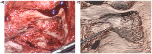
show comparisons between still frames from intra-operative videos and the corresponding renderings of the same patients in the virtual surgical environment. These results represent a sample from our library of cases, and include cochlear implantation (), resection of a glomus tympanicum tumor (), and removal of cholesteatoma lesions ( and ). In each case, the same salient anatomical or pathological features can be observed in both the intra-operative video and in the rendering from the simulation. These correspondences indicate that the virtual surgical environment can be expected to assist the surgeon in understanding the anatomy, extent of pathology, and difficulty of access or exposure that he or she is likely to encounter in the operating room for each particular patient.
Figure 11. Snapshots comparing the actual (a) and virtual (b) procedures for a 20-year-old man who presented with progressive bilateral sensorineural hearing loss and was deemed a good candidate for cochlear implantation. The operative photograph shows the mastoidectomy and facial recess approach during cochlear implant insertion on the right. The arrow identifies the capitulum of the stapes in the middle ear while the triangle shows the location of the cochleostomy through which the cochlear implant electrode is inserted. In the simulation view, the cochlea has been segmented in blue.
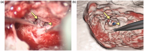
Figure 12. Snapshots comparing the actual (a) and virtual (b) procedures for a 35-year-old man who presented with right conductive hearing loss secondary to a middle ear globus tympanicum tumor. The operative photograph shows the external auditory canal as seen through the microscope. The tympanomeatal flap has been retracted anteriorly to show the middle ear contents. The ossicles can be seen with the arrow pointing to the manubrium of the malleus. The triangle identifies the tumor, shown in green in the simulation view.
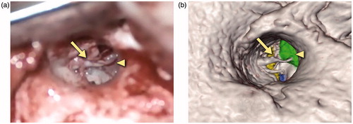
Figure 13. Snapshots comparing the actual (a) and virtual (b) procedures for a 12-year-old girl with a history of right-sided congenital cholesteatoma. She had previously undergone a two-stage tympanomastoidectomy with ossicular reconstruction, and subsequently presented with a maximal conductive loss and evidence of an ear canal cholesteatoma. She underwent right canalplasty with resection of external auditory canal cholesteatoma. The operative view shows the mastoidectomy performed to access the cholesteatoma (arrow) which has been segmented in white in the simulation view.
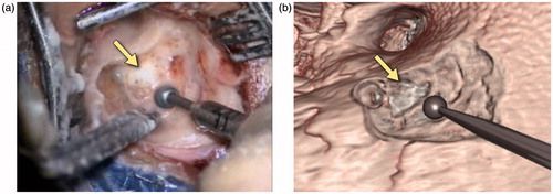
Figure 14. Snapshots comparing the actual (a) and virtual (b) procedures for a 63-year-old woman with a history of a left jugular foramen cholesteatoma who had underwent several procedures to remove the cholesteatoma. She subsequently underwent a left hypotympanic transjugular approach to the jugular foramen. The operative and simulation views show the approach used to access the jugular foramen and the pointer identifies the location of the cholesteatoma. This has not been segmented in the simulation view. Of note, no further drilling was required in this re-revision surgery and, as can be seen, the bony contours in the operative and simulation environments are similar.
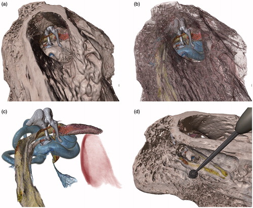
shows a rendering of MicroCT image data of a cadaver specimen within the virtual surgical environment. While there is no video of a specific dissection performed on this specimen, we use the high-resolution CT data with a detailed segmentation to provide an indication of the level of fidelity that can be achieved within the simulator if the challenges of working with clinical scans, such as limited resolution and image noise, were not obstacles. Key anatomical structures relevant to temporal bone surgery, including the ossicles, cochlea, semicircular canals, facial nerve, chorda tympani, stapedius and tensor tympani muscles, and the jugular bulb, were colorized to make them visually distinct (). The surrounding bone tissue may be rendered opaque, fully transparent, or at various in-between levels to reveal underlying structures, depending on the type of visualization desired. This specimen was found to be particularly useful for demonstrating various surgical approaches to the middle and inner ear anatomy ().
Figure 15. View through the external auditory canal of a MicroCT specimen in the virtual surgical environment. Tissue such as bone can be rendered opaque (a), semi-transparent to partially reveal structures underneath (b), or completely hidden to examine internal structures in detail (c). A partial dissection of the facial recess to reveal the stapes and round window is shown in (d).
The virtual surgical environment was designed with modest computing system requirements in order to minimize potential barriers to its deployment in a clinical setting. The software can be run on Microsoft Windows, Mac OS X, or Linux operating systems, and supports a variety of commercial haptic interfaces. In an effort to encourage use and dissemination of this technology, we have made the virtual surgical environment software, along with a subset of the cases described in this article, available to interested parties by request through the project’s web site at http://med.stanford.edu/cardinalsim.html.
Discussion
The work described in this article represents a step towards the use of an interactive virtual environment to prepare for temporal bone surgical procedures. We have described the design of a virtual surgical environment specifically for the purpose of patient-specific surgical simulation. It was shown that pre-operative image data can be used to facilitate simulation of key aspects of surgical interventions that took place for a variety of temporal bone pathology. Computational techniques were developed to achieve high-fidelity haptic and visual rendering that enabled a natural and realistic virtual dissection process. Our findings indicate that the virtual surgical environment can accurately predict the surgical exposure, spatial relationships of anatomical structures and landmarks, and the location of pathology that may be encountered in the operating room.
At present, anatomic segmentation is the rate-limiting step in effectively using our virtual surgical environment in a clinical workflow. While it is possible to conduct meaningful simulations directly from pre-operative CT image data, relying solely on radiodensity values to differentiate tissue types without explicitly performing segmentation, our experience indicates that the most useful simulations occur when segmentations of key anatomical structures are included. We are investigating the possibility of incorporating interactive segmentation methods directly into the virtual surgical environment, as a part of the scene preparation stage, to circumvent the need for external software tools and to optimize the simulation workflow. We are hopeful that future advances in segmentation processes can be incorporated to further the acceptance and utility of patient-specific rehearsal.
Though we strove to maximize haptic and visual fidelity in our work, the look and feel of the simulation falls decidedly short of the actual surgical experience. Much of this can be attributed to current limitations of haptic interfaces, computing power, and real-time algorithmic methods. We have shown that advances in computational methods can enable patient-specific simulation for surgical rehearsal, and that even if we are not yet able to simulate entire procedures with fidelity indistinguishable from the real experience, we can still extract useful and meaningful knowledge not otherwise available.
Simulations developed for surgical rehearsal may have very different fidelity requirements from those intended to introduce skills to novice surgeons. Teaching technical skills may require considerably greater realism. For example, learning the amount of force to apply to a drill for bone removal in a given location, or how to recognize a nerve covered with tissue, blood, and irrigation fluid is critical to performing safe cranial base surgery. The acquisition of such skills rely on interpreting subtle and variable visuohaptic cues that are yet unattainable in our system. However, the case may be quite different for a surgeon who already has a foundation in surgical techniques, but wishes to rehearse managing the challenges of a particular patient’s anatomy. This would appear to require less fidelity, so long as the geometric relationships and tissue manipulation remain accurate. For surgical rehearsal, the ease of dissection and flexibility to encourage exploration become higher priorities than realism so long as the virtual geometry remains recognizable to the surgeon.
Clearly tools such as the virtual surgical environment described require objective validation to ensure that they can benefit a surgeon in preparing for an operative case. We intend to carry out such prospective studies in the future as our system becomes further refined. We see value in the establishment of dynamic shared simulation databases containing anonymized patient data that can be explored and manipulated collaboratively between networks of surgeons with different levels of experience. This would enable surgical education and preoperative preparation similar to that currently offered in residency and fellowship, but using simulation to augment the interchange of knowledge. Another area requiring attention is the means through which insights gained during rehearsal can be optimally incorporated into the actual procedure in the operating room.
Although we have focused our efforts on cranial base applications, we anticipate that the methods described can be generalized to a variety of surgical procedures. We are encouraged by the assumption that the more a surgeon is familiar with working in and around specific anatomy, the more he or she is likely to be effective. It is likely that with time, the fidelity of surgical rehearsal will reach a point where entire procedures can be simulated in a virtual environment with an astonishing degree of realism. We are confident that offering surgeons an opportunity to practice in such an environment holds great potential to improve the delivery of surgical care.
Funding information
This work was supported by the National Institutes of Health, National Library of Medicine [grant number R01 LM010673-03].
Acknowledgements
The authors would like to acknowledge Sara Schvartzman, Joseph Lee, and Jonas Forsslund for their contributions and assistance in the development of the virtual surgical environment described in this work.
Disclosure statement
The authors have no other declarations of interest to report.
References
- Calhoun PS, Kuszyk BS, Heath DG, et al. Three-dimensional volume rendering of spiral CT data: theory and method. RadioGraphics. 1999;19:745–764.
- Rubin GD, Beaulieu CF, Argiro V, et al. Perspective volume rendering of CT and MR images: applications for endoscopic imaging. Radiology. 1996;199:321–330.
- Wiet GJ, Bryan J, Dodson E, et al. Virtual temporal bone dissection simulation. Stud Health Technol Informatics. 2000;70:378.
- Wiet GJ, Stredney D, Sessanna D, et al. Virtual temporal bone dissection: an interactive surgical simulator. Otolaryngol Head Neck Surg. 2002;127:79–83.
- Wiet GJ, Schmalbrock P, Powell K, et al. Use of ultra-high-resolution data for temporal bone dissection simulation. Otolaryngol Head Neck Surg. 2005;133:911–915.
- Kerwin T, Shen H-W, Stredney D. Enhancing realism of wet surfaces in temporal bone surgical simulation. IEEE Trans Visual Comp Graph. 2009;15:747–758.
- Wiet GJ, Stredney D, Kerwin T, et al. Virtual temporal bone dissection system: OSU virtual temporal bone system: development and testing. Laryngoscope. 2012;122:S1–S12.
- Petersik A, Pflesser B, Tiede U. Realistic haptic volume interaction for petrous bone surgery simulation. Comp Assist Radiol Surg. 2002;1:252–257.
- Pflesser B, Petersik A, Tiede U, et al. Volume cutting for virtual petrous bone surgery. Comp Aided Surg. 2002;7:74–83.
- Tolsdorff B, Petersik A, Pflesser B, et al. Individual models for virtual bone drilling in mastoid surgery. Comp Aided Surg. 2009;14:21–27.
- Agus M, Giachetti A, Gobbetti E, et al. A multiprocessor decoupled system for the simulation of temporal bone surgery. Comput Visual Sci. 2002;5:35–43.
- Agus M, Giachetti A, Gobbetti E, et al. Real-time haptic and visual simulation of bone dissection. Presence. 2003;12:110–122.
- Neri E, Sellari Franceschini S, Berrettini S, et al. IERAPSI project: simulation of a canal wall-up mastoidectomy. Comp Aided Surg. 2006;11:99–102.
- Morris D, Sewell C, Blevins N, et al. A collaborative virtual environment for the simulation of temporal bone surgery. Proceedings of Medical Image Computing and Computer-Assisted Intervention. Springer; 2004. p. 319–327.
- Morris D, Sewell C, Barbagli F, et al. Visuohaptic simulation of bone surgery for training and evaluation. IEEE Comp Graph Appl. 2006;26:48–57.
- Sewell C, Morris D, Blevins NH, et al. Validating metrics for a mastoidectomy simulator. Stud Health Technol Informatics. 2007;125:421–426.
- Sewell C, Morris D, Blevins NH, et al. Providing metrics and performance feedback in a surgical simulator. Comp Aided Surg. 2008;13:63–81.
- Chan S, Li P, Hoon Lee D, et al. A virtual surgical environment for rehearsal of tympanomastoidectomy. Stud Health Technol Informatics. 2011;163:112–118.
- Solvsten Sorensen M, Mosegaard J, Trier P. The visible ear simulator: a public PC application for GPU-accelerated haptic 3D simulation of ear surgery based on the visible ear data. Otol Neurotol. 2009;30:484–487.
- Kraut J, Hochman JB, Unger B. Temporal bone surgical simulation employing a multicore architecture. Proceedings of IEEE Canadian Conference of Electrical and Computer Engineering; 2013. p. 1–6.
- Eugene Merchant M. Mechanics of the metal cutting process. I. Orthogonal cutting and a type 2 chip. J Appl Phys. 1945;16:267.
- Archard JF. Contact and rubbing of flat surfaces. J Appl Phys. 1953;24:981–988.
- Jacobs CH, Pope MH, Berry JT, et al. A study of the bone machining process—orthogonal cutting. J Biomech. 1974;7:131–136.
- Engel K, Hadwiger M, Kniss JM, et al. Real-time volume graphics. Wellesley (MA): A K Peters; 2006.
- Chan S, Conti F, Blevins NH, et al. Constraint-based six degree-of-freedom haptic rendering of volume-embedded isosurfaces. Proceedings of IEEE World Haptics Conference; 2011. p. 89–94.
- McNeely WA, Puterbaugh KD, Troy JJ. Six degree-of-freedom haptic rendering using voxel sampling. Proceedings of SIGGRAPH 98; 1999. p. 401–408.
- Bruyninckx H, Khatib O. Gauss’ principle and the dynamics of redundant and constrained manipulators. Proceedings of IEEE International Conference on Robotics and Automation; 2000. p. 2563–2568.
- Redon S, Kheddar A, Coquillart S. Gauss’ least constraints principle and rigid body simulations. Proceedings of IEEE International Conference on Robotics and Automation; 2002. p. 517–522.
- Colgate JE, Stanley MC, Brown JM. Issues in the haptic display of tool use. IEEE/RSJ International Conference on Intelligent Robots and Systems, volume 3; 1995. p. 140–145.
- Arbabtafti M, Moghaddam M, Nahvi A, et al. Physics-based haptic simulation of bone machining. IEEE Trans Haptics. 2011;4:39–50.
- Wiggins KL, Malkin S. Drilling of bone. J Biomech. 1976;9:553–559.
- Krause WR. Orthogonal bone cutting: saw design and operating characteristics. J Biomech Eng. 1987;109:263–271.
- Plaskos C, Hodgson AJ, Cinquin P. Modelling and optimization of bone-cutting forces in orthopaedic surgery. Medical Image Computing and Computer-Assisted Intervention; 2003. p. 254–261.
- Dillon NP, Kratchman LB, Dietrich MS, et al. An experimental evaluation of the force requirements for robotic mastoidectomy. Otol Neurotol. 2013;34:e93–e102.
- Wu J, Yu G, Wang D, et al. Voxel-based interactive haptic simulation of dental drilling. Proceedings of ASME International Design Engineering Technical Conferences & Computers and Information in Engineering; 2009.
- Misra A, Finnie I. Some observations on two-body abrasive wear. Wear. 1981;68:41–56.
- Weaver JK. The microscopic hardness of bone. J Bone Joint Surg. 1966;48-A:273–288.
- Zysset PK, Edward Guo X, Edward Hoffler C, et al. Elastic modulus and hardness of cortical and trabecular bone lamellae measured by nanoindentation in the human femur. J Biomech. 1999;32:1005–1012.
- Drebin RA, Carpenter L, Hanrahan P. Volume rendering. Comp Graph. 1988;22:65–74.
- Krüger J, Westermann R. Acceleration techniques for GPU-based volume rendering. Proceedings of IEEE Visualization; 2003. p. 287–292.
- Tiede U, Schiemann T, Höhne KH. High quality rendering of attributed volume data. Proceedings of IEEE Visualization; 1998. p. 255–262.
- Hadwiger M, Berger C, Hauser H. High-quality two-level volume rendering of segmented data sets on consumer graphics hardware. Proceedings of IEEE Visualization; 2003. p. 301–308.
- Chen JYC, Thropp JE. Review of low frame rate effects on human performance. IEEE Trans Syst Man Cybernet A Syst Humans. 2007;37:1063–1076.
- Li W, Mueller K, Kaufman A. Empty space skipping and occlusion clipping for texture-based volume rendering. Proceedings of IEEE Visualization; 2003. pages 317–324.