
Abstract
Unicondylar Knee Replacement (UKR) is an orthopedic surgical procedure to reduce pain and improve function in the knee. Load-bearing long-standing antero-posterior (AP) radiographs are typically used postoperatively to measure the leg alignment and assess the varus/valgus implant orientation. However, implant out-of-plane rotations, user variability, and X-ray acquisition parameters introduce errors in the estimation of the implant varus/valgus estimation. Previous work has explored the accuracy of various imaging modalities in this estimation. In this work, we explored the impact of out-of-plane rotations and X-ray acquisition parameters on the estimation of implant component varus/valgus angles. For our study, we used a single CT scan and positioned femoral and tibial implants under varying orientations within the CT volume. Then, a custom software application was used to obtain digitally reconstructed radiographs from the CT scan with implants under varying orientations. Two users were then asked to manually estimate the varus/valgus angles for the implants. We found that there was significant inter-user variability (p < 0.05) in the varus/valgus estimates for the two users. However, the ‘ideal’ measurements, obtained using actual implant orientations, showed small errors due to variations in implant orientation. We also found that variation in the projection center does not have a statistically significant impact (p < 0.01) on the estimation of implant varus/valgus angles. We conclude that manual estimates of UKR implant varus/valgus orientations are unreliable.
Introduction
Unicondylar Knee Replacement (UKR) is an orthopedic surgical procedure to reduce pain and improve function in the knee.[Citation1] Postoperative radiological assessment of the implant alignment is an important predictor of the success of the procedure. Load-bearing long-standing antero-posterior (AP) radiographs are typically used postoperatively to measure the leg alignment and assess the varus/valgus implant orientation. In this assessment, errors arise due to using two-dimensional (2D) measurements to make three-dimensional (3D) alignment evaluations. These errors are aggravated when the implants have out-of-plane rotations. Inter-user variability and variations in X-ray acquisition parameters also contribute to errors in this assessment. Previously research groups have compared the accuracy of different imaging modalities in estimating the implant orientations. Hirschmann et al. compared conventional radiographs with transverse 2D computed tomography (CT) slices and 3D CT reconstruction in their accuracy to estimate the position and orientation of total knee replacement (TKR) implants.[Citation2] Holme et al. also compared use of 3D CT and plain radiographs for estimating the orientation of UKR implants.[Citation3] However, long-standing AP radiographs continue to be the preferred postoperative imaging modality due to its ease of acquisition and cost-effectiveness. In our paper, we hypothesize that manual measurements from AP radiographs to evaluate the UKR implant component varus/valgus angles are affected by implant out-of-plane rotations and, hence, unreliable.
In this paper, to evaluate our hypothesis, we addressed the following questions: (1) What is the impact of implant out-of-plane rotation on estimation of UKR implant component varus/valgus angles from AP radiographs? (2) What is the impact of acquisition parameters on the estimation of UKR implant component varus/valgus angles from AP radiographs?
Materials and methods
Data and software
For our study, we used a single hip-toe CT image to serve as a reference for implant placement. A customized software application was developed using Visualization Toolkit (VTK) and Insight Segmentation and Registration Toolkit (ITK) libraries to open and visualize DICOM CT images, and manually position a 3D surface model at any orientation within the CT volume.[Citation4,Citation5] An ITK utility application named ‘xRayGenerator’ was developed to obtain a digitally reconstructed radiograph (DRR) from a CT image. The utility allowed setting of parameters such as: (1) distance from source to X-ray plate, (2) distance from center of CT volume to the X-ray plate, (3) x, y, and z rotation and translation of the input CT volume, (4) translation of the X-ray source, and (5) resolution of the output X-ray projection image. ‘Icy,’ an open-source software,[Citation6] and Adobe Illustrator (AI) (Adobe Systems, San Jose, CA), a commercially available software, were used to estimate implant orientations from the radiographs.
Study design
For this study, we used one CT image in a fixed pose, but varied the femoral and tibial implant orientations and the radiograph projection center as seen in . First, the CT data were imported into the Navio system.[Citation7] The validated Navio planning software was then used to select the implant (Stride, Smith & Nephew) size and set its orientation. For the femoral implant, the following orientation parameters were used: (1) varus angle: 0° and 5°; (2) Flexion: 23° and 28°; and (3) external rotation: −1°, 9°, and 19°. For the tibial implant, the following orientation parameters were used: (1) varus: 0° and 5°; (2) anterior slope: 0° and 5°; and (3) internal rotation: 7°, 12°, and 17°. Thus, 12 different orientations were obtained for the tibial and the femoral implant. These orientations spanned the range of implant variations empirically seen in patients. Besides the orientation matrices, the landmark points used to define the anatomic reference axes used by the Navio software for the femoral and tibial implants were also noted down. Subsequently, surface models of the appropriately sized femoral and the tibial implants were positioned in the CT volume by using the previously obtained orientation matrices. A Hounsfield unit value of 6000 was assigned to voxels in the CT volume that lay inside the implant. The modified CT volume containing the implant was then projected to obtain the DRRs (). To generate these radiographs, the following parameters were used: source-to-X-ray plate distance set to 1828.8 mm, volume center to plate distance = 200 mm, and output image resolution = 1 × 1 mm. Again two translations were applied to the CT volume so that the projection center was either at the left knee center or at the center of line joining the two knee centers. However, no z-rotation was applied to the CT volume. Thus, 24 sets of DRRs were generated, one for each implant orientation, and X-ray projection center. For each parameter set, the ground truth landmark points were also projected to obtain the true femoral and tibial mechanical axes used to determine the varus/valgus angle for the implant. Another 24 sets of DRRs were obtained that contained the projection of the 3D mediolateral-axis of the oriented implant. These radiographs were used to obtain the ‘ideal’ measurements for implant orientation. Two users were asked to mark the implant orientations in the first set of DRRs using Icy or AI. The projected ground truth landmark points used by Navio were then used as a reference to calculate the varus/valgus angles measured by the users as shown in .
Figure 1. Schematic representation of the experimental setup. (1) and (2) shows the two positions of the X-ray source for the projection center at the center of the procedure knee and lying in between the two knees, respectively. D1 and D2 are the distances of the center of CT volume and X-ray source from the X-ray plate respectively. (A) (neutral), (B) (internal rotation), and (C) (external rotation) are the three different rotations applied to the femoral implant.
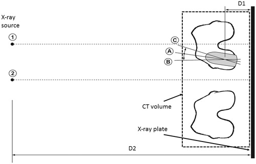
Figure 2. Partial view of DRRs obtained under varying implant orientations.
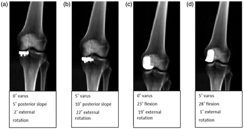
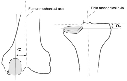
Figure 3. Estimation of varus/valgus angles for tibial and femoral implants. The tibial and femoral mechanical axes are estimated using the ground truth positions of the hip center, knee centers, and the ankle center. α1 and α2 are the varus/valgus angles estimated for the femoral and the tibial implants, respectively.
Results
The user measurements for estimating the implant varus/valgus angle are summarized in and and graphically presented in . We see from the plots that user 1 had higher average measurement errors for calculating the varus/valgus angles for the femoral implant and lower measurement errors for calculating the varus/valgus angles for the tibial implant. Using the paired ‘Student’s’ t-test, we found that femoral measurements for the two users were significantly different (p < 0.005). The measurements for the tibial implant were also found to be significantly different (p < 0.05). We also see that both users have very large measurement errors that are biased towards the valgus. From the ideal measurements, we see that variation of femoral implant external rotation from positive to negative leads to a valgus bias in the measurements for the femoral implant. Similar variations are seen for the tibial implant measurements with an increasing valgus bias in the measurements as the internal rotation varies from low to high. No consistent variations in the implant component varus/valgus measurements are observed due to variations in flexion in case of femoral implant and posterior slope in case of tibial implant.
Figure 4. Box plot for measurement errors while estimating the femoral and tibial varus/valgus angles.
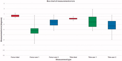
Table 1. Femoral varus/valgus estimations for varying projection center.
Table 2. Tibial varus/valgus measurements for varying projection center.
Using the paired Student’s t-test, we found that for both the femoral and tibial implant for both the users, the results obtained when the projection center was at the procedural knee center was not significantly different than that obtained when the projection center was between the two knees (p < 0.01).
Discussion
Postoperative radiological assessment of the knee serves to evaluate the success of arthroplasty procedures and identify potential postoperative complications. The evaluation involves measurements of postoperative knee alignment and implant orientations relative to the surgical plan. Both these measurements are currently carried out manually by using hip-to-ankle load-bearing AP radiographs.[Citation8] Previously, many researchers have focused on evaluating the impact of limb rotation on radiological assessment.[Citation9–12] Hirschmann et al. compared conventional radiographs with transverse 2D CT slices and 3D CT reconstruction in their accuracy to estimate the position and orientation of TKR implants.[Citation2] They found that rotational measurements are estimated more accurately using 3D CT reconstruction. Holme et al. also found 3D CT estimates to be more reliable than conventional radiographs for estimating UKR implant orientations.[Citation3] However, due to cost-effectiveness long-standing AP radiographs continue to be the preferred imaging modality. Here, we evaluate our hypothesis that manual estimations of UKR implant varus/valgus angles from AP radiographs are unreliable as they are affected by implant out-of-plane rotations.
Our study suffered from several limitations. First, only two observers were involved in carrying out the measurements in our study. Both observers were trained in the domain of orthopedic surgery but were not surgical doctors. Second, in order to limit the total number of measurements, the implant orientation variation was kept small. Moreover, we focused only on the left knee for the study. Third, in our study, we did not use any load-bearing images. The X-ray images were obtained using DRRs and were obtained from cadavers in a supine position. However, the purpose of the study was to evaluate the impact of variation of orientation, and acquisition parameters on radiological measurements. Hence it was not necessary to use load-bearing images, although we acknowledge the additional effect weight bearing may have on the leg alignment in radiographic images.
Our work related to UKR implant component alignment measures shows that there measurements made by different users have a large intra-user variability. The measurements for two users can also be significantly different (p < 0.05). However, the ‘ideal’ measurements showed small errors due to variations in implant orientation. Thus, automated/semi-automated could be potentially used to obtain reliable UKR implant measurements from postoperative radiographs.[Citation13,Citation14] We also found that variation in the projection center does not have a statistically significant change in the estimation of the tibial and femoral varus/valgus angles (p < 0.01).
Disclosure statement
Both the authors are employees of Smith & Nephew.
References
- Kozinn SC, Scott RD. Surgical treatment of unicompartmental degenerative arthritis of the knee. Rheum Dis Clin North Am. 1988;14:545–564.
- Hirschmann MT, Konala P, Amsler F, et al. The position and orientation of total knee replacement components: a comparison of conventional radiographs, transverse 2D-CT slices and 3D-CT reconstruction. J Bone Joint Surg Br. 2011;93:629–633.
- Holme TJ, Henckel J, Cobb J, et al. Quantification of the difference between 3D CT and plain radiograph for measurement of the position of medial unicompartmental knee replacements. Knee. 2011;18:300–305.
- Schroeder W, Martin K, Lorensen B. Visualization toolkit: an object-oriented approach to 3D graphics, 4th ed. Clifton Park (NY): Kitware Inc.; 2006.
- Ibanez L, Schroeder W, Ng L, et al. The ITK software guide: the insight segmentation and registration toolkit. Clifton Park (NY): Kitware Inc.; 2003.
- de Chaumont F, Dallongeville S, Chenouard N, et al. Icy: an open bioimage informatics platform for extended reproducible research. Nat Methods. 2012;9:690–696.
- Jaramaz B, Nikou C. Precision freehand sculpting for unicondylar knee replacement: design and experimental validation. Biomed Tech (Berl). 2012;57:293–299.
- Cooke TD, Scudamore RA, Bryant JT, et al. A quantitative approach to radiography of the lower limb. Principles and applications. J Bone Joint Surg Br. 1991;73:715–720.
- Radtke K, Becher C, Noll Y, et al. Effect of limb rotation on radiographic alignment in total knee arthroplasties. Arch Orthop Trauma Surg. 2010;130:451–457.
- Lonner JH, Laird MT, Stuchin SA. Effect of rotation and knee flexion on radiographic alignment in total knee arthroplasties. Clin Orthop. 1996;331:102–106.
- Hunt MA, Fowler PJ, Birmingham TB, et al. Foot rotational effects on radiographic measures of lower limb alignment. Can J Surg J Can Chir. 2006;49:401–406.
- Swanson KE, Stocks GW, Warren PD, et al. Does axial limb rotation affect the alignment measurements in deformed limbs? Clin Orthop. 2000;371:246–252.
- Hoff WA, Komistek RD, Dennis DA, et al. Pose estimation of artificial knee implants in fluoroscopy images using a template matching technique. Proceedings 3rd IEEE Workshop on Applications of Computer Vision; 1996 Dec 2–4. p. 181, 186.
- Imai S, Higashijima K, Ishida A, et al. Determination of the position and orientation of artificial knee implants using markers embedded in a bone: preliminary in vitro experiments. Med Eng Phys. 2003;25:419–424.