
ABSTRACT
Radiofrequency ablation (RFA) is a crucial alternative treatment for liver cancer with the advantages of minimal invasion and a fast prognosis. However, two problems limit its further application: the orientation of the puncture point and the ablation of large tumors. The optical surgery navigation system in the RFA presents a promising approach for solving the localization problem in the puncturing process, which greatly increases puncture accuracy and has overcome the disadvantages of traditional RFA surgery. In addition, the use of multiple electrodes in the RFA (multi-probe RFA) is proposed and is applied clinically to deal with large tumors. In this study, we present a multi-probe RFA model using the finite element method (FEM) combined with a self-developed optical surgical navigation system. A real 3D liver model was adopted as an effective reference. Based on this model, two-probe RFA simulations were performed under different active modes. An analysis was conducted from the perspective of the temperature and electric potential fields and cell necrosis. The simulation results showed that different active modes had separate advantages and were suitable for different situations. Understanding their advantages can not only help doctors make surgical plans that fit the patients’ conditions, but also the understanding can offer a virtual surgery platform for further development in the preoperative planning of RFA incorporated with the surgery navigation system.
Introduction
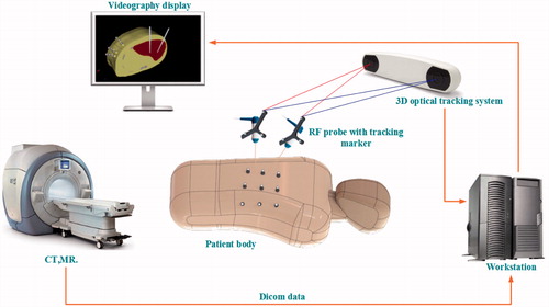
With over 800,000 people dying from the disease each year, liver cancer has risen to become the third most common cause of cancer-related deaths worldwide.[Citation1] However, like many other cancers, liver cancer is difficult to diagnose at an early stage. Only 10–20% of liver cancer patients can undergo surgical excision, which is considered the most efficient method in the treatment of hepatocellular cancer (HCC).[Citation2] In this circumstance, interventional ablation techniques are becoming much more popular, because they have fewer post-operative complications and are suitable for a wide range of patients. Even if only certain patients are eligible to undergo resection, some of them may choose interventional therapy, because of the low cost and fast prognosis. Therefore, interventional ablation techniques are crucial in oncotherapy in many ways. Microwave ablation (MWA) and Radiofrequency ablation (RFA) are two major minimally invasive approaches. MWA is less dependent on the targeted tissue environment and thus suits many parts of the human body, such as the lungs and bones, while RFA is reliant on the tissue environment and acts well in tissues that have good electric and thermal conductivity, such as the liver and kidney.[Citation3] Moreover, the RFA has good maneuverability and low complication rates compared with MWA. Consequently, the RFA is commonly used in liver cancer treatment. However, two problems currently limit its further application. The first problem is how to determine the orientation of the puncture point. Though CT scans of the patients can illustrate the location of the tumors, doctors can only rely on their memories of the scans during the puncturing. Thus, the normal process is repeatedly adjusting the location of the electrodes and scanning every time after adjustments until the site error is within the acceptable level. The whole process is inefficient and harmful, because it increases the trauma and the radiation doses for the patients. As surgical navigation emerges as a new application in clinical practice,[Citation4] it serves to provide guidance for doctors or robots in the process of puncturing and shows promising prospects that resolve the first problem in the RFA. Image-guided RFA has a wide range of applications in oncotherapy,[Citation5] and its application is available in many relevant operations.[Citation6] Electromagnetic and optical navigation are most commonly used in surgery. Compared to electromagnetic navigation, optical surgical is more popular, because it is insensitive to ferromagnetic materials and has large working volumes and high accuracy.[Citation7] In our previous work,[Citation8–11] a near-infrared optical tracking system (NIOTS) based on point registration was developed and reached an accuracy of 0.1 mm, as shown in . In this system, an automatic patient-to-image registration was realized through customized fiducial markers attached to the patient’s abdomen. A workstation was employed for data processing, and transmissions were collected through a CT or MR. A holder loaded with three retro-reflective fiducial markers was also fixed to the surgical instrument. Thus, the movement of the surgical instrument could be tracked and its tip position displayed on a screen in real time. Experiments showed that this method could largely improve the efficiency of a percutaneous treatment. Also, there were some other navigational patterns that served in the clinical practice, such as ultrasonic navigation, and so on.[Citation12] To illustrate for the doctors, surgical navigation generally requires 2D profiles with 3D rebuilding and shows the visualization of the tissues. The 3D rebuilding and visualization of tissues are indispensable in surgical planning and pattern choices. Thus, this study reconstructed a real liver model based on the CT data of patients.
Figure 1. Near-infrared optical tracking system.
The second problem is how to continually expand ablation lesions. At present, patients with small tumors have achieved relatively high survival rates in resections and local ablations.[Citation13] However, the cure for large tumors (diameter >3 cm) remains a great challenge in clinical medicine. Patients in such situations may not undergo surgical resections, and doctors have to perform ablation surgery several times.[Citation14,Citation15] This will bring additional pain to the patients and prolong the surgical times. The solution for this problem may rely on the application of a multi-probe RFA. It could not only save time, but also adjust to the distributions of the tumors for optimization. Hänsler et al. [Citation16] conducted clinical trials on 37 patients with 64 HCCs with tumor diameters ranging from 3 cm to 6 cm. The results showed that a multi-probe RFA for relatively larger tumors had a lower local recurrence rate than that for a single electrode. Mulier et al. [Citation17] studied the optimal inter-electrode distance for a bipolar four-electrode system using the FEM and ex vivo experiments. The temperature distributions of a multi-probe RFA is not a simple super-positioning of the temperature of each electrode. In fact, it is affected by the coupled electric field, with the performance of the electric field being connected by the choice of active modes. In a multi-probe RFA, there are three commonly used active modes, namely, the consecutive, simultaneous, and switching modes.[Citation18] This study simulated these modes and analyzed their separate advantages according to the results. Approaches to expand the ablation scope also covered the use of an auxiliary solution and the development of expandable electrodes. The FEM is an ordinary research method in the RFA research. Alba et al. [Citation19] built a model of the cool-tip electrode to examine the relationship between roil-offs and tissue temperatures. Electric and thermal conductivity were critical factors affecting the results of the simulation. To identify the differences among the FEM models using electric and thermal conductivity coefficients of different mathematical expressions, Trujillo et al. [Citation20] compared 14 mathematical expressions from two groups.
In our previous studies,[Citation8–11] we built a NIOTS based on marked points to solve the issue of accurate puncturing. The system serves to guide doctors in the puncturing process to avoid the situations of repeated scanning and adjustments and reduce the surgical time and radiation doses for patients. In addition, to resolve the issue of expanding the ablation zone, a multi-probe RFA was proposed as a promising approach. However, as a newly emerging therapy, the clinical practice of a multi-probe RFA is far from sophisticated. In this study, two-probe RFA simulations were performed under different active modes to identify their difference for clinical references.
Methods
Geometry of RF electrodes
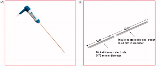
The model was based on the single perfusion electrode of StarBuster UniBlate produced by Rita as shown in . The StarBuster UniBlate is made of a titanium-nickel alloy. It is characterized by abrasive resistance, corrosion resistance, high damping capacity, and hyper-elasticity that can effectively prevent the electrode from breaking off and distorting, which are issues that affect surgical security and curative effects. About 4 mm of the front end of the electrode was covered with Peek resin to generate an even thermal output in addition to a large sub-globular ablation lesion for lowering the recurrence rate. The inside tube for the saline injection within the electrode was neglected in the geometric model. The size of the electrode is shown in .
Figure 2. RF electrode, (A) Rita’s StarBuster UniBlate perfusion electrode, (B) simplified model.
Geometry of the liver model
The current geometric models of the RFA applied in the FEM are mostly simplified 2D planar models.[Citation21] These structures simplify the shape of the liver, thus they cannot offer an effective reference for RFA surgery guidance. Hence, this study reconstructed a real 3D liver model from CT images to serve for the simulations of the multi-probe RFA.
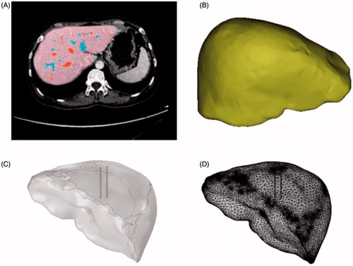
This study acknowledges the cooperation of the Guangdong Provincial People’s Hospital, which provided the liver CT data and the equipment for the RFA. All CT data in this paper were obtained from the hospital’s Philips 128 CT scanner, which has a minimum scan span reach of 0.625 mm. After scanning, the liver model was extracted from the corresponding CT data by Bessel–Fourier moments and colored by the supporting software of the CT for post-processing.[Citation22] The process is illustrated in . This study focused on the comparison of different active modes; thus, we neglected the effect of the blood vessels. A 3D liver model was then reconstructed by extracting the contours of the liver. Noise removals and surface fittings were conducted to provide a smooth surface with lesser vertices; this potentially increased the speed and accuracy of the calculations. The processed model is shown in . The liver and electrode models were then imported separately into COMSOL. The geometry and mesh are shown in ).
Figure 3. 3D liver models, (A) processed CT images, (B) optimized liver model, (C) geometric model, (D) mesh model.
FEM modeling
Mathematical equations
Heat exchanges occur in organisms, biological tissue, and ambient environments in three patterns, namely, heat conduction, thermal convection, and thermal radiation. A physiological phenomenon in heat exchange is called metabolism and blood perfusion.[Citation23] In normal conditions, the organism may remain stable through a variety of regulation mechanisms, such as maintaining the inner temperature at around 37 °C. However, the RF electrode may break the balance and cause a temperature increment. The Pennes equation,[Citation24] as shown below, is commonly used in describing heat transfer in biological tissue:
(1)
(2)
In EquationEquation (1)(1) , the left-hand side represents the heat exchange per unit volume as temperature variation, ρ is the tissue density and its unit is kg/m3, and Cp is the tissue specific heat and its unit is J/kg·K. The unit of T is K in terms of temperature of tissue, and t denotes time with a unit of s. The first term on the right-hand side represents heat conduction and k is the heat conduction rate with a unit of W/m·K. The second term Qb refers to the heat driven away by blood perfusion, which is known as the heat sink effect of blood vessels.[Citation25] Because the effect of the blood vessels was ignored in this study, Qb was set to 0. The third term denotes the heat produced by tissue metabolism. The fourth term represents joule heat, which indicates the tissue temperature increment caused by resistance losses. This factor is a determinant in the production of tissue thermal ablation and its value depends on tissue conductivity and electrode potentials. The equation is presented as follows:
(3)
where, J is current density, E is the electric field intensity, σ is the conductivity with a unit of S/m, and V is the voltage impressed on the electrode.
The operating frequency of the RF electrode is about 500 kHz with an electromagnetic wavelength of about 600 m, which is much larger than that of a pinpoint diameter.[Citation26] Therefore, the major pattern of the RF electrode during energy transfer is conductivity with a low capacitive coupling. Under this condition, the model can be regarded as a quasi-electrostatic field.[Citation27] In such an electric field, equations are solved using the formulae of electrostatic fields, illustrated as follows:
(4)
In RFA, the electric field is inspired by the RF electrode acting on the entire liver. Resistance heat can be produced as the result of an electric field action, which leads to the coupling thermal field. These two physical fields have a common effect on the distribution of the temperature field and the electric potential field across the liver model. EquationEquations (1)–(4) are the solution for the electrical-thermal-coupled problems in the RFA.
Materials and boundary conditions
This model consists of three domains, the electrode, trocar, and liver domains. Based on the literature,[Citation28] the material properties of each domain are shown in .
Table 1. Thermal and electrical properties of the materials.
In the model, the liver surface was considered isolated and grounded, and the electrode surface was loaded with voltage V0:
(5)
(6)
(7)
V0 represents a 22-V constant direct current loaded on the RF electrode. By applying the quasi-static approximation, the direct current voltage was calculated from the model, which corresponded to the root-mean-square value of the RF voltage used.[Citation27] The electric field equation was set to compute under a stable state, while the equation for the bio-heat field was computed under a time-dependent state. The adiabatic boundary was applied, and the human organism was maintained at a constant temperature. Thus, the liver boundary was applied in the first-class boundary condition:
(8)
(9)
where, T is the temperature in the liver, Tb is the human body temperature at 37 °C, and q is the thermal flux.
Results and discussion
Multi-probe ablation has three common active modes: the consecutive, simultaneous, and switching modes. This study analyzed these modes to provide guidance in clinical practice.
Simultaneous mode
The simultaneous mode featured an RF generator that was connected to multiple RF electrodes working at the same time. Essentially, the RFA transforms the electrical energy loaded in the electrodes into the heat energy of the organisms to kill tumors through hyperthermia. Therefore, a regular electric field and temperature changes were the focus of analysis in the simulation results. First, we emulated a two-probe ablation measuring 1 cm under the simultaneous active mode and added a 22 V direct current to the electrodes. After 10 min, the temperature field and the electric potential field distribution were displayed, including 50 °C on the isothermal surface after a 1 min ablation, as shown in .
Figure 4. Ablation results, (A) temperature distribution, (B) Electric Potential distribution and, (C) isosurface of 50 °C.
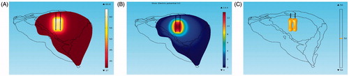
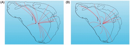
shows that the super-positioning of the temperature field between the two electrodes does not appear. On the contrary, the temperature between the two electrodes was lower than that of the area outside the two electrodes. This phenomenon was caused by the electrostatic shielding under the electrostatic field. shows that the distribution of the electric flux line is sparse in the area between the two electrodes; this is also known as the Faraday cage.[Citation29,Citation30] shows the electric field line of three electrodes under the simultaneous mode in which the effect of the electrostatic screening is obvious.
Figure 5. Streamline of current density, (A) two needles, (B) three needles.
In addition to the effect of the electrostatic shielding, the degree of ablation was also affected by the distance between the two electrodes. To test this influence, we adjusted the horizontal distance between the two electrodes to 0.5, 1, 1.5, and 2 cm before the calculation. The results showed that when the distance was less than 1 cm, the tissue between the needles was totally inside the isosurface of 50 °C after ablating for 10 min, thus indicating a complete coagulation according to the judgment standard in clinical practice. When the distance was larger than 2 cm, the combined effect of the ablation was equivalent to that of the two needles. Therefore, a relatively close distance between the needles should be maintained for large tumors. When dealing with tumors that are relatively small and disperse, applying the simultaneous mode can save time.
Consecutive mode
The consecutive mode features an RF generator connected to multiple RF electrodes working in sequence. The isothermal surface of 50 °C under the consecutive mode is shown in .
Figure 6. Isosurface of 50 °C under the consecutive mode, (A) t = 10 min, (B) t = 10.5 min, (C) t = 11.5 min.
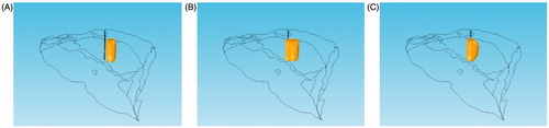
At t = 10 min, the first RF needle stopped the process of ablation, whereas the second needle began to ablate. At this moment, heat still gathered around the first RF needle. When the second needle ablated, its surrounding temperature began to increase, whereas the temperature around the first one gradually decreased to that of the body surface. The temperature could decrease during ablation under the consecutive mode, but the damage to the tissue injured by hyperthermia was irreversible. Arrhenius was introduced to examine the effectiveness of the ablation under the sequential active mode. The exponential relations of the tissue temperature, exposure time, and tissue damage built on the cell survivability research were acquired experimentally. If the exposure temperature and time of the given tissues are known, the cell damage rate of these tissues can be calculated through the Arrhenius equation, expressed as follows:
(10)
where, Ω(t) is thermal damage, c(0) is the initial concentration of living cells, and c(t) represents the concentration of living cells as a function of time. A is the frequency factor (2.984 × 1080 s−1), ΔE is the activation energy (5.064 × 10⁵ J·mol−1), and T is the absolute temperature as a function of time.[Citation31] We chose a series of points in the geometry space where the coordinates of these points were (−5, 0, 70), (5, 0, 70), and (−5, 0, 70) respectively, as shown in . The temperature curves and proportions of cell necrosis at these points were then calculated in the consecutive mode in addition to the simultaneous mode. The rate of the necrotic cell near the RF needle that ablated early remained the same, but increased rapidly after 10 min when affected by the electrode that ablated later.
Figure 7. Ratio of cell necrosis, (A) 3D points, (B) temperature varying with time, (C) necrotic ratio varying with time.
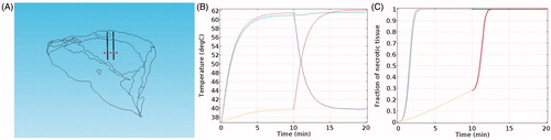
To examine the efficiency of the consecutive and the simultaneous modes, we compared the volume of the ablated zone by applying the same amount of RF energy under the two modes. In and , ‘necrotic tissue’ is defined as the area where the rate of necrotic cells reaches 100%.
Table 2. Volume of necrotic tissue varying with time under the consecutive mode.
Table 3. Volume of necrotic tissue varying with time under the simultaneous mode.
We calculated the volume of the necrotic tissue at different times by evaluating the integrals of the necrotic areas. The results showed that the volume of the necrotic tissue was slightly larger under the consecutive mode than under the simultaneous mode. Thus, the simultaneous mode is recommended for the treatment of small and separate tumors for time-saving. However, when ablating tumors with a high-demand on the ablation range, the consecutive mode should be adopted, even though this requires additional time.
Switching mode
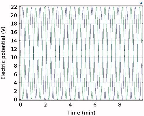
The switching mode featured an RF generator connected to multiple RF electrodes, which work alternately at certain time interval, such as 1 s. Considering the volume of the calculations, we applied sine wave voltages on the two electrodes with one phase difference at an angular frequency of 0.15. The electric potential on both electrodes is shown in .
Figure 8. Sine wave voltages on the electrodes.
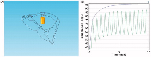
In the switching mode, the two RF electrodes work at different times. Thus, the electrostatic screen and the corresponding temperature trough did not emerge, as shown in . However, with the same voltage (22 V), temperature reductions and oscillating waveforms appeared in the switching mode, as shown in . This indicated that the temperature of the tissue was greatly affected by voltage and that its reaction was fast. To some extent, the switching mode is the combination of the consecutive and the simultaneous modes, which not only avoided the electrostatic screen but also saved time. However, the switching mode requires a relatively high voltage to maintain the temperature at a set degree.
Figure 9. Ablation results under switching mode, (A) Isosurface of 50 °C, (B) temperature on the tip of one electrode.
Summary
To identify the differences among the three active modes when applying the multi-probe RFA, simulations under different conditions were carried out. The results showed that the electric fields of the RF needles reacted with one another and generated an electrostatic screen under the simultaneous mode. The ablation result was best at the distance of 1 cm when applying two electrodes. Thus, doctors should adopt such a mode when the tumors are relatively small and disperse. The consecutive mode can prevent the effect of the electrostatic screen and can acquire a relatively large necrotic volume at the cost of additional time. Thus, this mode should be considered when the destroyed range is preferred over the time taken for the procedure. The simultaneous mode has the advantage of the two modes, and thus it can avoid an electrostatic screen and save time. However, temperature fluctuations appear as the voltage changes, and the whole temperature becomes lower than that of the other modes. The voltage should be increased accordingly when this mode is adopted.
The pursuit of higher accuracy and stability supported by various imaging and other kinds of medical devices is a current trend in medicine, especially for minimally invasive surgery. In this study, we analyzed three active modes under the condition of a multi-probe RFA via the FEM to provide certain references in accordance with individualized treatment plans. However, there are still some limitations in this study. First, we reconstructed only the geometric surface of the liver, while the blood vessels and the microstructures of the tissues were neglected. Second, in the simulation of the switching mode, the alternating frequency of the voltage was set at relatively slow in comparison to the clinical application to simplify the calculations; this may result in the decrease of accuracy to some degree. In addition, ex vivo or in vivo experiments can be conducted to better support the simulation results.
Conclusion
As an interventional ablation therapy, the RFA has the advantage of minimal trauma, security, effectiveness, and a quick recovery, and has become a crucial alternative treatment for liver cancer. However, two problems limit its further application; these are the problems of the orientation of the puncture point and the ablation of large tumors. To resolve the first problem, we developed an optical surgery navigation system that could provide real-time guidance for doctors to make accurate punctures. For the second problem, a multi-probe RFA was proposed as a promising solution. As a newly emerging therapy, the clinical practice of a multi-probe RFA is far from sophisticated. One of the important issues in this treatment method is to identify the proper active mode in applications. Thus, we performed a multi-probe RFA under different active modes using the FEM based on a real 3D liver model. Analyses were conducted from the perspectives of temperature fields, electric potential fields, and cell necrosis. The results showed that the temperature and electric potential fields varied with the different active modes, which led to different performances in the ablation results. Therefore, we make suggestions about the suitable situations for different active modes. The limitations of the study are also subsequently pointed out. To perform ablations for different type of tumors for different patients, the determination of the working mode alone is not sufficient. Future work can explore comprehensive surgical planning, including the routes and angles of insertion and the numbers and positions of the RF electrodes. The advantages of interventional therapy can be maximized with the incorporation of a surgery navigation system and preoperative planning, which provide the foundation for an exact ablation.
Disclosure statement
The authors declare no conflict of interest in this study.
Funding
This research was funded by the State Scholarship Fund under [Grant CSC NO. 201408440326], the Pearl River S&T Nova Program of Guangzhou under [Grant No. 2014J2200049] and [No. 201506010035], the Project of Outstanding Young Teachers’ Training in Colleges and Universities of Guangdong under [Grant No. YQ2015091], the Features Innovative Program in Colleges and Universities of Guangdong under [Grant No. 2015KTSCX069], the Guangdong Provincial Science and Technology Program under Grant [No. 2013B090600057, No. 2014A020215006 and 2016A020220006].
References
- Li D, Kang J, Golas BJ, et al. Minimally invasive local therapies for liver cancer. Cancer Biol Med. 2014;11:217–236.
- Wright AS, Mahvi DM, Haemmerich DG, et al. Minimally invasive approaches in management of hepatic tumors. Surg Technol Int. 2001;11:144–153.
- Brace CL. Radiofrequency and microwave ablation of the liver, lung, kidney, and bone: what are the differences? Curr Prob Diagn Radiol. 2009;38:135–143.
- Mezger U, Jendrewski C, Bartels M. Navigation in surgery. Langenbeck Arch Surg. 2013;398:501–514.
- Chi C, Du Y, Ye J, et al. Intraoperative imaging-guided cancer surgery: from current fluorescence molecular imaging methods to future multi-modality imaging technology. Theranostics. 2014;4:1072–1084.
- Mountney P, Stoyanov D, Yang G-Z. Three-dimensional tissue deformation recovery and tracking. IEEE Signal Proc Mag. 2010;27:14–24.
- Yang R, Wang Z, Liu S, et al. Design of an accurate near infrared optical tracking system in surgical navigation. J Lightwave Technol. 2013;31:223–231.
- Lin Q, Yang R, Cai K, et al. Real-time automatic registration in optical surgical navigation. Infrared Phys Technol. 2016;76:375–385.
- Lin Q, Yang R, Cai K, et al. Strategy for accurate liver intervention by an optical tracking system. Biomed Opt Exp. 2015;6:3287–3302.
- Cai K, Yang R, Lin Q, et al. Near-infrared camera calibration for optical surgical navigation. J Med Syst. 2016;40:1–12.
- Cai K, Yang R, Ning H, et al. An automatic algorithm for distinguishing optical navigation markers used during surgery. Dyna. 2015;90:203–209.
- Park MJ, Kim YS, Rhim H, et al. A comparison of US-guided percutaneous radiofrequency ablation of medium-sized hepatocellular carcinoma with a cluster electrode or a single electrode with a multiple overlapping ablation technique. J Vasc Intervent Radiol. 2011;22:771–779.
- Solbiati L, Livraghi T, Goldberg SN, et al. Percutaneous radio-frequency ablation of hepatic metastases from colorectal cancer: long-term results in 117 patients. Radiology. 2001;221:159–166.
- Chen M-H, Yang W, Yan K, et al. Large liver tumors: protocol for radiofrequency ablation and its clinical application in 110 patients—mathematic model, overlapping mode, and electrode placement process. Radiology. 2004;232:260–271.
- Chen MH, Yang W, Yan K, et al. Radiofrequency ablation of problematically located hepatocellular carcinoma: tailored approach. Abdom Imag. 2008;33:428–436.
- Hänsler J, Frieser M, Tietz V, et al. Percutaneous ultrasound-guided radiofrequency ablation (RFA) using saline-perfused (wet) needle electrodes for the treatment of hepatocellular carcinoma – long term experience. Ultraschall Med. 2007;28:604–611.
- Mulier S, Jiang Y, Wang C, et al. Bipolar radiofrequency ablation with four electrodes: ex vivo liver experiments and finite element method analysis. Influence of inter-electrode distance on coagulation size and geometry. Int J Hyperthermia. 2012;28:686–697.
- Mulier S, Miao Y, Mulier P, et al. Electrodes and multiple electrode systems for radiofrequency ablation: a proposal for updated terminology. Eur Radiol. 2005;15:798–808.
- Alba J, González-Suárez A, Trujillo M, et al. Theoretical and experimental study on RF tumor ablation with internally cooled electrodes: when does the roll-off occur? Conf Proc IEEE Eng Med Biol Soc. 2011;2011:314–317.
- Trujillo M, Berjano E. Review of the mathematical functions used to model the temperature dependence of electrical and thermal conductivities of biological tissue in radiofrequency ablation. Int J Hyperthermia. 2013;29:590–597.
- Zhang R, Liu H, Li H. Finite element analysis of radiofrequency ablation process in soft tissue sarcomas. Paper presented at: 4th IEEE International Conference on Information Science and Technology (ICIST), 2014 Apr 26–28; Shenzhen, Guangdong, China:358–363.
- Bin X, Jian-Feng M, Xuan W. Image analysis by Bessel-Fourier moments. Patt Recog. 2010;43:2620–2629.
- Shih T-C, Horng T-L, Huang H-W, et al. Numerical analysis of coupled effects of pulsatile blood flow and thermal relaxation time during thermal therapy. Int J Heat Mass Trans. 2012;55:3763–3773.
- Pennes HH. Analysis of tissue and arterial blood temperatures in the resting human forearm. J Appl Physiol. 1948;1:93–122.
- Pillai K, Akhter J, Chua TC, et al. Heat sink effect on tumor ablation characteristics as observed in monopolar radiofrequency, bipolar radiofrequency, and microwave, using ex vivo calf liver model. Medicine. 2015;94:e580.
- Sheu TW, Chou C, Tsai S, et al. Three-dimensional analysis for radio-frequency ablation of liver tumor with blood perfusion effect. Comp Meth Biomech Biomed Eng. 2005;8:229–240.
- Berjano EJ. Theoretical modeling for radiofrequency ablation: state-of-the-art and challenges for the future. Biomed Eng. 2006;5:24.
- Tungjitkusolmun S, Staelin ST, Haemmerich D, et al. Three-dimensional finite-element analyses for radio-frequency hepatic tumor ablation. IEEE Transact Biomed Eng. 2002;49:3–9.
- Lee JM, Han JK, Kim HC, et al. Switching monopolar radiofrequency ablation technique using multiple, internally cooled electrodes and a multichannel generator: ex vivo and in vivo pilot study. Investig Radiol. 2007;42:163–171.
- Barauskas R, Gulbinas A, Vanagas T, et al. Finite element modeling of cooled-tip probe radiofrequency ablation processes in liver tissue. Comp Biol Med. 2008;38:694–708.
- Dos Santos I, Haemmerich D, Schutt D, et al. Probabilistic finite element analysis of radiofrequency liver ablation using the unscented transform. Phys Med Biol. 2009;54:627–640.