
Abstract
Background: The use of reconstruction plates and lag screws has been recommended for fractures to the posterior wall of the acetabulum. However, little information about the rigidity of recommended forms of fracture fixation is available. This study aimed to evaluate the biomechanical difference among the fixation systems.
Methods: A posterior wall fracture, which is represented by softer elements with lower elastic modulus, was created along an arc of 40–90° about the acetabular rim. Three different fixation systems: screws alone, reconstruction plate with screws, reconstruction plate with T-shaped plates were used to fix the posterior wall fractures to the acetabulum.
Results: All three fixation system can be used to obtain good functional outcomes. The reconstruction plate with T-shaped plates was beneficial to increasing the effective stiffness, decreasing the stress concentration and enhancing the rigidity of fracture fixation. So this fixation system served an ideal result in the analysis.
Conclusion: Theoretically, the reconstruction plate with T-shaped plates system may reduce many of the risks and limitations compared to the other fixation systems. This fixation system may result in a clinical benefit.
1. Introduction
Fractures of the posterior wall are the most common of the acetabular fractures,[Citation1] constituting one fourth to one third of all acetabular fractures.[Citation2] Most posterior wall fractures are comminuted and associated with an impaction injury of the articular surface into the underlying cancellous bone along the margin of the fracture line.[Citation3,Citation4]
Traditionally, surgical fixation of posterior wall acetabular fractures is accomplished by interfragmentary screws alone or combination with other implants such as reconstruction plates or buttress plates. Im et al. [Citation5] retrospectively examined 15 patients with a single fragmented or moderately comminuted posterior wall acetabular fractures who had been treated with internal fixation using screws alone. They found that the use of screws alone can produce acceptable results for selected posterior wall acetabular fractures. Goulet et al. [Citation6] created reproducible simple fractures and osteotomies of the posterior wall in twenty paired hemi-pelvis from fresh human cadaver. They found that the fixation of transversely comminuted fractures treated with a reconstruction plate and screws was also significantly higher than that of fixation of such fractures with screws alone. Additional a reconstruction plate and accessory spring plates serve highest stiffness than the former two conditions. Liu et al. [Citation7] used six formalin-preserved cadaveric pelvis with Acetabular Tridimensional Memory Alloy-Fixation System (ATMFS) to measure distribution of contact area and pressure between the acetabulum and the femoral head. They concluded that ATMFS fixation could result in a clinical benefit. Schwab et al. [Citation8] reported a new technique, cervical vertebrae plates, for operative fixation of posterior wall acetabular fractures. The new technique showed clinical outcomes similar to the published literature for standard pelvic reconstruction plates.
Although secure fixation of the posterior wall acetabular fracture was critical, little information about the validity or the mechanical properties of recommended forms of fracture fixation was available.[Citation9] The purpose of this study was to create a FE model and evaluate the biomechanics of three fixation systems for the posterior wall acetabular fractures through FE analysis. The biomechanics of these fixation systems are assessed based on the maximum displacement, stress distributions, force transfers, and displacements along their fracture lines.
2. Materials and methods
2.1. Finite element model of pelvic
The present study was licensed by the Hospitals Ethics Committee. A 3D FE model of the pelvis was created on the basis of the computed tomography (CT) scan images with a slice width of 0.5 mm of a Chinese male (40 years old, 175 cm tall, and 65 kg weight) (). The point cloud was converted to form the surface of the pelvic by using Mimics. These data were then imported into Ansys-ICEM and Hyper-mesh to produce the FE model. Mesh division was carried out on each part of the tissue by a combined artificial and automatic division method. The soft tissues (i.e. end-plates, cartilage and pubic symphysis) between pelvic bones were meshed into hexahedron elements in Hypermesh. The pelvic ligaments were modeled by truss elements (element size was 2 mm), additional they were permitted only axial tensile force transmission. The mesh density was selected when further refinements did not appreciably improve the accuracy of the calculations. The material properties of the pelvis and fixation systems are shown in .
Figure 1. Finite element model of the pelvis. (A) Whole pelvic model, (B) iliac bone.
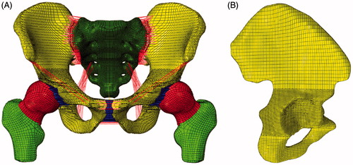
Table 1. The material properties of the pelvic tissues.
2.2. Fragment lines
The simulated fracture of the posterior wall began at 40° posterior to the acetabular vertex along the rim of the acetabulum and continued along the arc of the posterior rim to 90° posterior to the vertex. The posterior wall articular fragment extended medially to include initially 1/3 of the width of the articular surface as measured from the posterior acetabular rim to the acetabular fossa throughout this 50° arc.[Citation7,Citation10] Here a series of mesh along the fracture line were weaken to represent posterior wall fractures.[Citation11,Citation12]
The material properties of the pelvic tissues and fixation systems are in .
2.3. Surgical techniques
The fixation system of posterior wall acetabular fractures was composed primarily of reconstruction plates and screws. Three different fixation systems (i.e. linear two-lag screws configuration, single reconstruction plate with two-lag screws, and single reconstruction plate combined with two T-shaped mini-plates) were created based on extensive clinical experience and have been recommended to stabilize fractures. Fracture fixation device made of Nitinol alloy (NiTi) will be more beneficial to fracture healing, therefore, the fixation systems were made in this material.[Citation13]
Linear two-lag screws configuration
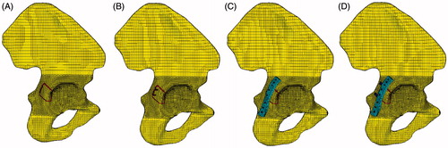
The first fixation system was composed of two lag screws.[Citation3,Citation5] The embedded contact, which could be used to specify the elements of host elements to constrain the translational degrees of freedom of the screws nodes, was used to restrict the slide between the interfaces of the screws and the bones. In our model, two screws with 3.5-mm diameter were implanted into the fracture component and intact bones ().
Figure 2. Fracture models. (A) Fracture component without any fixation systems, (B) the first fixation system: Linear two-lag screws configuration, (C) the second fixation system: single reconstruction plate with two-lag screws, (D) the third fixation system: single reconstruction plate with T-shaped mini-plates.
Single reconstruction plate with two-lag screws
For comminuted posterior wall fractures, treatment with lag screws alone could not achieve a better clinic effort due to the reason that the comminuted fracture components could not stay in the anatomical position. Therefore, a reconstruction plate combine with lag screws were reconstructed with articular fragment reduction and iliac bone grafting.[Citation5,Citation7] This fixation system was accomplished by contouring the posterior wall plate to the intact bone.[Citation5] Six screws placed through the plate into the remaining intact pelvis in two sides, additional two lag screws were implanted into the fracture component and intact bones. The contact between plates and cortical surface were defined as face-to-face contact with a friction coefficient of 0.1.[Citation14] Coupling constraints were used between plates and screws in order to make sure no relative sliding.
Single reconstruction plate combined with two T-shaped mini-plates
A marginal impaction of fragments or a severe comminution with more than three major fragments was considered to be the strong contraindication to fixation with screws alone [Citation5]. A reconstruction plate combined with two underlying T-shaped mini-plates could result in the larger contact area of the buttress on the comminuted marginal portion of the posterior wall, especially providing additional support when fractures were involve in the superior roof.[Citation15] The reconstruction plate was placed in the same position as the second fixation system. Additionally, the two T-shaped mini-plates underlying the reconstruction plate were used to maintain anatomical reduction of intercalary osteochondral fragments, obviously eight small screws were used to place the two mini-plates into intact bones.
2.4. Loading and boundary
The purpose of this study was to evaluate the validation of the fixation systems on standing stance and last period of standing up from a sitting position. The model could analysis the fractures displace from sitting position to standing phase by changing the femur angle and adding hip joint force.
Hip joint forces have also been calculated during several activities,[Citation16–22] while the difference between the analytical results shown is dramatic. This may be due to the applied optimization strategies and to the employed anatomic and physiologic assumptions and simplifications. Bergmann calculated the values and directions of the hip joint force at eight phases during a waling circle.[Citation23] The value of hip joint force changes with the walking phase (i.e. the hip direction). He also used telemetering total hip prostheses to study the relationship between the median peak forces and walking speed. The median peak forces increased with the walking speed. Brown et al. [Citation24] explore body borne loads impact walk-to-run and running biomechanics, while further study appears needed to determine how load carriage impairs maximal locomotor performance. The pelvic-loading condition changes consistently during walking and standing up from a sitting position (e.g. chair), while previous studies of the pelvis, including subject-specific studies have made extensive simplifications with regards to the load and boundary conditions used during analysis. On these conditions, we only consider the double-limb stance and last period in the standing up condition from sitting. Four angles (15°, 10°, 5°, 0°(double-limb stance)) in the normal model and fracture model were used to represent this period (). These angles between the iliac bone (longitudinal body axis) and the femur in the A/P-plane (flexion/extension) were produced by rotate femur center axis. Static vertical loads (600N and 1200N were) load on the upper surface of sacral bone.
Figure 3. Pelvic model under four femur angle: (A) 0°, (B) 5°, (C) 10°, (D) 15°.
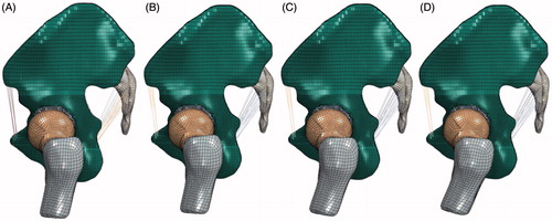
The double-limb stance was similar with existing models as previously described by Sawaguchi et al. [Citation25] The model was placed in a specific neutral position defined with the iliac wings level (coplanar in the horizontal plane).[Citation10] In the sagittal plane, the proximal femoral shaft was vertical. In the sagittal plane, the proximal femoral shaft was vertical. The degrees of freedom of the end of the femur were restrained to represent the double-limb stance.
3. Results
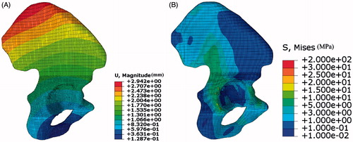
shows the stress and displacement distributions in standing stance under body weight (600 N). The largest displacement in the model was 2.94 mm, which was similar to the values in the previous studies (2.70 mm in the Phillips et al. [Citation26] and 2.71 mm in the Wu et al. [Citation27]). The regions of stress concentration were observed at the superior rim of the acetabulum and on the ilium superior to the acetabulum, which was agreement with previous models.[Citation28,Citation29] These findings show that the FE model could be used to evaluate the biomechanical property of pelvic.
Figure 4. Displacement and stress distribution in two iliac bones. (A) Displacement distribution in iliac bone with large mesh size, (B) displacement distribution in iliac bone with small mesh size.
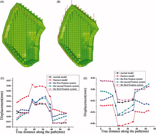
The largest displacement in normal model, fracture model and three fixation systems under different load and boundary conditions are shown in .
Table 2. The largest displacement in normal model, fracture model and three fixation systems under different load and boundary conditions.
presents the largest displacement in all models under different conditions. The largest displacement in normal models almost keep the minimum level compared to other models, the third fixation system (the reconstruction plate with T-shaped plates system) followed. The facture models suffer largest displacements under four femur angles. The third fixation system (the reconstruction plate with T-shaped plates system) was an optimization for the posterior wall fracture, due to the reason that this fixation system was able to make the model in a good state.
The stress distribution in the iliac bone under different femur rotation angles with no fixation systems under 600N and 1200N static vertical loads are shown in and .
Figure 5. The stress distribution in the iliac bone under different femur rotation angles with no fixation systems under 600N static vertical loads. (A) 0°, (B) 5°, (C) 10°, (D) 15°.
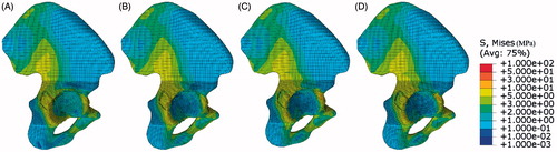
Figure 6. The stress distribution in the iliac bone under different femur rotation angles with no fixation systems under 1200N static vertical loads. (A) 0°, (B) 5°, (C) 10°, (D) 15°.
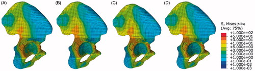
The stress value changes with both static vertical loads and femur angles, while the pattern almost remains the same, what is meant by this is the fact that acetabular rim suffer higher stress than the center of acetabular suits for all the situations. An impressive phenomenon was stress pattern changes gradually throughout the iliac bone with the angle of the femur, means the stress pattern under 10° almost same as it is in the 15°. A conclusion can be concluded that the stress distribution pattern changes a little within certain ranges, so the double-limb stance under normal upper body weight would be considered as the classic pattern to evaluate the biomechanics of the fixation systems.
The von Mises stress in five different boundary conditions (normal, fracture and three fixation systems) is shown in . Once the fracture occurred, the load transfer path changed. In the normal model, the highest stress occurred at the posterior side of the acetabulum, especially near ligamentum transversum acetabuli, the anterior side of acetabulum taken the second place. In contrast, the stress in the center of acetabular bone were much lower than its value in the limbus of acetabular, it may be the lowest position in the iliac bone, near one tenth of limbus. There was no stress fields observed near the anterior side of acetabular.
Figure 7. Stress distribution in iliac bones. (A) Stress distribution in normal model, (B) fracture component without any fixation systems, (C) the first fixation system, (D) the second fixation system, (E) the third fixation system.
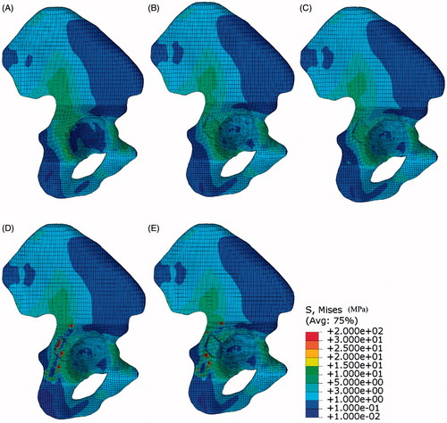
In the fracture and fixation systems models, the highest stress occurred at the place around the corner of fracture line. The stress distributed in most parts of iliac bone was lower than the value in the normal model, it led to the stress level in the fracture model which was lower than the value in the normal model. While the stress distributed in the center of acetabular bone was higher than its value in the normal model, so the load transfer path changed a little compared to the normal model, it transfer to femur though the center of acetabular compared the posterior side of the acetabular in the normal model.
The stress differences between fixation systems were stress distribution, especially in the fracture component, positions screws implanted and the place attaching the reconstruction plate edge. The stress distribution along the limbus of acetabulum () was shown in the . A big deviation has taken place in the fracture component. The stress noted in the anterior side of acetabular was higher than its value in the normal model. The distribution in the other place almost same as the normal model.
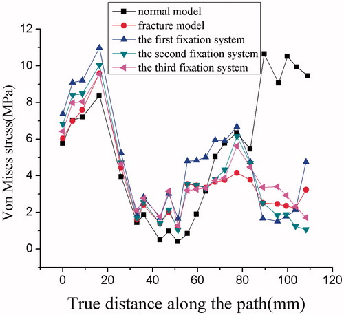
Figure 8. Von Mises stress along the limbus of acetabulum.
The relative displacement difference between fracture outer line and inner line under different systems was shown in . The fracture model under the third fixation system has the minimum difference respond to the normal model. The displacement difference along the axis of the circle was smaller than the value of the path along the 50° arc, the middle part of the path. This may be due to the reason that the outer load was distributed in the axial direction. It can be concluded that the fracture line under the reconstruction plate and two T-shaped plated system can be healed to intact with least error.
Figure 9. The relative displacement difference between different systems. (A) The outer line of the fracture component, (B) the inner line of the fracture component, (C) the relative displacement difference between different systems, (D) the relative displacement difference in the vertical direction component (i.e. the load direction) between different systems.
A conventional von Mises stress pattern corresponding to each fixation systems is shown in . The stress distributed unevenly in linear 2-lag screws. The highest stress region was noted at the middle of screws, attaching the cancellous bone fracture line. The higher stress region was noted in the inferior side of screws. The lower stress region was demonstrated in the upper section of the screws, inserted into the fracture component, while the inferior hole corresponds to the higher stress value in the outer cortex (). There was no stress field observed near to the screws head exposed the iliac bone.
Figure 10. Stress distribution in fixation systems. (A) The first fixation system, (B) the second fixation system, (C) the third fixation system.
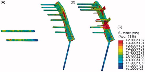
The role of reconstruction plate can be shown in the second system. In the second system, the highest stress region was noted at the middle of the plate, attaching the cortical bone fracture line. The stress distribution in the screws was evaluated as similar to the first fixation systems, means decreased from the center of screws to the ends. So the reconstruction plate was placed to keep fracture component in the original position to form the artificial surface of intact bone.
When compared with the second fixation system, it is noted that the stress distribution was in the same pattern in the third fixation system. The two T-shaped mini-plates suffered considerable stress. The highest stress region was noted in the region between reconstruction plate and T-shaped mini-plates.
4. Discussion
This study aims to simulate the mechanical behavior of the posterior wall acetabular fractures and assess the biomechanical mechanism of the fixation systems recommended for fracture stabilization. Three different fixation systems generally applied (i.e. linear two-lag screws configuration, single reconstruction plate with two-lag screws, and single reconstruction plate combined with two T-shaped mini-plates) were constructed to stabilize fractures. The mechanisms of the three fixation systems were evaluated in terms of maximum displacement, stress distributions, and displacements along fracture lines.
Compared to the normal model, the stress distribution changed when the fracture occurred or fixation systems applied. The major difference of the stress distribution occurred in the fracture component. The higher stress located the place around the corner of fracture line after the fracture, and the stress level in the most part of the iliac bone was lower than the value in the normal model (). Additionally, the stress level in iliac bone under the third fixation system was lower than that in other systems. Previous work indicated that a large posterior wall articular defect of the acetabulum significantly alters the force transmission across the hip.[Citation10] Specifically, there was a transition from evenly distributed loading along the acetabular articular surface to loading concentrated mainly in the superior portion of the articular surface after fracture.[Citation10]
Besides stress distribution, the maximum displacement of different boundary conditions was compared. The displacement of fracture models were higher than those obtained from normal model and fixation systems. It can be concluded that the stiffness of the fracture model arrange the lowest position. Additionally, the stiffness of the first fixation system was lower than the value obtained from the other two fixation systems. James et al found the stiffness of fixation of the transversely comminuted fractures that had been achieved with use of a reconstruction plate and screws was significantly higher than that achieved with fixation with screws alone.[Citation6] They also found that the load to failure of the fixation of concentrically comminuted fractures was significantly higher when a reconstruction plate and accessory plates had been used than that when a reconstruction plate alone had been employed.[Citation6] This finding was corresponding to the fact that the maximum displacement in the third fixation system (single reconstruction plate combined with two T-shaped mini-plates) was lower than the former two systems.
The fragments were unstable to keep the original position due to bone fracture. The displacement difference between the fracture components reflects the shear resistance of the internal fixation after the operation. Upward or slip displacements, which are produced by the push of the femoral head-acetabular roof, reflect the overall standing stability of the hip.[Citation27] The posterior wall fracture under the third fixation system has the minimum difference response compared to the normal model. Additionally, the upward displacement difference under the third fixation system was no longer statistically different from the normal model. Previous works indicated that the plate combined with interfragmentary screws could increase the contact areas and decrease the contact pressure compared with fracture models, therefore, the load could distribute evenly. It can be concluded that the fracture line under the third fixation system can be healed to intact with least error.
The lag screws, attached by the cancellous bone fracture line were more stressed than those in other positions. This finding may be ascribed to either the difference in the relative displacements of the split parts or the change of the material (). The screws could fasten the fragments by compression to generate a close fit of the irregular surfaces that is more resistant to shearing and tensional forces, so the simple or moderately comminuted posterior wall fractures could be treated with screws alone if the fragments remain viable with pre-served soft tissue attachments.[Citation30] The stress distribution in the reconstruction plate was similar to that in the lag screws; means the positions attached the fracture line served higher stress level in other positions (). While for comminuted fractures with little fragments will need complex fixation system, rather than screws alone, to keep the fragments in the anatomical position, because the reconstruction plates could provide better mechanical support as a buttress plate and can act as cortical substitutes in comminuted fractures. The function of reconstruction plate was to keep fracture component in the original position to form the artificial surface of intact bone. The two T-shaped mini-plates suffered considerable stress compared to the reconstruction plate (), and the stress in the third fixation system distributed evenly than that in the second fixation system, and the highest stress value was lower than the value in the former system. These phenomenon were beneficial to the load transformation, that the load could transfer through fixation system rather than fracture components. So the third fixation system served an ideal result on condition that the plate failure is mainly the fatigue fracture due to the stress concentration.
Although the study had demonstrated the comparison of three fixation systems, the model had its limitations. Firstly, the hip joint forces have also been calculated during several activities by some scholars previously, while the difference between the analytical results shown is dramatic due to the applied optimization strategies and physiologic assumptions.[Citation18,Citation19,Citation21] This paper only consider the double-limb stance and the last period in the standing up condition from sitting, and two static vertical loads value (body weight and twice value) were loaded on the upper surface of sacral bone. Additionally, Bone quality also influences the long-term success of implant treatment, with poor bone quality leading to lower success rates. Compared to bone quality, the methods of fixation systems serve a greater effect on pelvic fracture.[Citation31] What’s more, the intra-articular penetration of screws or the invalidation of fixation systems should be concerned in the clinical results. Therefore, further basic research on the assessment of pelvic injury should be conducted in the future to reach a precise conclusion.
5. Conclusion
The purpose of this study was to evaluate the biomechanics mechanism of three typical fixation systems for posterior wall acetabular fracture through FE method. All the three fixation systems could enhance biomechanical stability significantly of the posterior wall acetabular fracture. Nonetheless, the reconstruction plate combined with T-shaped plates system was beneficial to the fractures due to the uniform stress distribution, balanced force transfer, and minor displacement difference to the normal model. Therefore, this fixation system was the optimal method to address the posterior wall acetabular fracture.
Acknowledgments
Ethical standards: Compliance with ethical standards. This article does not contain any studies with human participants or animals performed by any of the authors.
Disclosure statement
All authors declares none conflict of interest.
Funding
This work is supported by the Top Young Academic Leaders of Shanxi and the Outstanding Innovative Teams of Higher Learning Institutions of Shanxi. The financial contributions are gratefully acknowledged.
References
- Ebraheim NA, Patil V, Liu J, et al. Reconstruction of comminuted posterior wall fractures using the buttress technique: a review of 32 fractures. Int Orthop. 2007;31:671–675.
- Judet R, Judet J, Letournel E. Fractures of the acetabulum: classification and surgical approaches for open reduction. Preliminary report. J Bone Joint Surg Am. 1964;46:1615–1646.
- Kim HT, Ahn J, Hur J, et al. Reconstruction of acetabular posterior wall fractures. Clin Orthop Surg. 2011;3:114.
- Saterbak AM, Marsh JL, Nepola JV, et al. Clinical failure after posterior wall acetabular fractures: the influence of initial fracture patterns. J Orthop Trauma. 2000;14:230–237.
- Im G, Shin Y, Song Y. Fractures to the posterior wall of the acetabulum managed with screws alone. J Trauma. 2005;58:300–303.
- Goulet JA, Rouleau JP, Mason DJ, et al. Comminuted fractures of the posterior wall of the acetabulum. A biomechanical evaluation of fixation methods. J Bone Joint Surg Am. 1994;76:1457–1463.
- Xin-wei L, Shuo-gui X, Chun-cai Z, et al. Biomechanical study of posterior wall acetabular fracture fixation using acetabular tridimensional memory alloy-fixation system. Clin Biomech (Bristol, Avon). 2010;25:312–317.
- Schwab JM, Zebrack J, Schmeling GJ, et al. The use of cervical vertebrae plates for cortical substitution in posterior wall acetabular fractures. J Orthop Trauma. 2011;25:577–580.
- Zha G, Sun J, Chen L, et al. Late reconstruction of posterior acetabular wall fractures using iliac crest. J Trauma Acute Care Surg. 2012;72:1386–1392.
- Olson SA, Bay BK, Pollak AN, et al. The effect of variable size posterior wall acetabular fractures on contact characteristics of the hip joint. J Orthop Trauma. 1996;10:395–402.
- Boccaccio A, Kelly DJ, Pappalettere C. A mechano-regulation model of fracture repair in vertebral bodies. J Orthop Res. 2011;29:433–443.
- Isaksson H, Comas O, van Donkelaar CC, et al. Bone regeneration during distraction osteogenesis: mechano-regulation by shear strain and fluid velocity. J Biomech. 2007;40:2002–2011.
- Geetha M, Singh AK, Asokamani R, et al. Ti based biomaterials, the ultimate choice for orthopaedic implants – a review. Prog Mater Sci. 2009;54:397–425.
- Andersen RC, O'Toole RV, Nascone JW, et al. Modified stoppa approach for acetabular fractures with anterior and posterior column displacement: quantification of radiographic reduction and analysis of interobserver variability. J Orthop Trauma. 2010;24:271–278.
- Zhang Y, Zhao X, Tang Y, et al. Comparative study of comminuted posterior acetabular wall fracture treated with the acetabular tridimensional memory fixation system. Injury. 2014;45:725–731.
- Brand RA, Pedersen DR, Davy DT, et al. Comparison of hip force calculations and measurements in the same patient. J Arthroplasty. 1994;9:45–51.
- Crowninshield RD, Johnston RC, Andrews JG, et al. A biomechanical investigation of the human hip. J Biomech. 1978;11:75–85.
- Dao TT, Marin F, Ho BTM. Ontology of the musculo-skeletal system of the lower limbs. Conf Proc IEEE Eng Med Biol Soc. 2007;2007:386–389.
- Moissenet F, Chèze L, Dumas R. A 3D lower limb musculoskeletal model for simultaneous estimation of musculo-tendon, joint contact, ligament and bone forces during gait. J Biomech. 2014;47:50–58.
- Paul JP. Force actions transmitted by joints in the human body. Proc R Soc Lond B Biol Sci. 1976;192:163–172.
- Röhrle H, Scholten R, Sigolotto C, et al. Joint forces in the human pelvis-leg skeleton during walking. J Biomech. 1984;17:409–424.
- Seireg A, Arvikar RJ. The prediction of muscular load sharing and joint forces in the lower extremities during walking. J Biomech. 1975;8:89–102.
- Bergmann G, Graichen F, Rohlmann A. Hip joint loading during walking and running, measured in two patients. J Biomech. 1993;26:969–990.
- Brown TN, O'Donovan M, Hasselquist L, et al. Body borne loads impact walk-to-run and running biomechanics. Gait Posture. 2014;40:237–242.
- Sawaguchi T, Brown TD, Rubash HE, et al. Stability of acetabular fractures after internal fixation: a cadaveric study. Acta Orthop. 1984;55:601–605.
- Phillips A, Pankaj P, Howie CR, et al. Finite element modelling of the pelvis: inclusion of muscular and ligamentous boundary conditions. Med Eng Phys. 2007;29:739–748.
- Wu Y, Cai X, Liu X, et al. Biomechanical analysis of the acetabular buttress-plate: are complex acetabular fractures in the quadrilateral area stable after treatment with anterior construct plate-1/3 tube buttress plate fixation? Clinics. 2013;68:1028–1033.
- Anderson AE, Peters CL, Tuttle BD, et al. Subject-specific finite element model of the pelvis: development, validation and sensitivity studies. J Biomech Eng. 2005;127:364–373.
- Phillips A. Numerical modelling of the pelvis and acetabular construct following hip arthroplasty. PhD thesis. The University of Edinburgh; 2005.
- Erkmen E, Şimşek B, Yücel E, et al. Comparison of different fixation methods following sagittal split ramus osteotomies using three-dimensional finite elements analysis: Part 1: advancement surgery-posterior loading. Int J Oral Maxillofac Surg. 2005;34:551–558.
- Culemann U, Holstein JH, Kohler D, et al. Different stabilisation techniques for typical acetabular fractures in the elderly – a biomechanical assessment. Injury. 2010;41:405–410.