
Abstract
Study design: Clinical trial for cervical screw insertion by using individualized 3-dimensional (3D) printing screw insertion templates device.
Objective: The objective of this study is to evaluate the safety and accuracy of the individualized 3D printing screw insertion template in the cervical spine.
Materials and methods: Ten patients who underwent posterior cervical fusion surgery with cervical pedicle screws, laminar screws or lateral mass screws between December 2014 and December 2015 were involved in this study. The patients were examined by CT scan before operation. The individualized 3D printing templates were made with photosensitive resin by a 3D printing system to ensure the screw shafts entered the vertebral body without breaking the pedicle or lamina cortex. The templates were sterilized by a plasma sterilizer and used during the operation. The accuracy and the safety of the templates were evaluated by CT scans at the screw insertion levels after operation.
Results: The accuracy of this patient-specific template technique was demonstrated. Only one screw axis greatly deviated from the planned track and breached the cortex of the pedicle because the template was split by rough handling and then we inserted the screws under the fluoroscopy. The remaining screws were inserted in the track as preoperative design and the screw axis deviated by less than 2 mm. Vascular or neurologic complications or injuries did not happen. And no infection, broken nails, fracture of bone structure, or screw pullout occurred.
Conclusion: This study verified the safety and the accuracy of the individualized 3D printing screw insertion templates in the cervical spine as a kind of intraoperative screw navigation. This individualized 3D printing screw insertion template was user-friendly, moderate cost, and enabled a radiation-free cervical screw insertion.
Introduction
The placement of screws has become a routine in spinal fusion surgery in recent years.[Citation1] Biomechanical studies have demonstrated that screw fixation, especially using pedicle screws, is the strongest and most reliable means to ensure the stabilization and fixation of specific spinal motion segments in the cervical vertebra.[Citation2,Citation3] However, there is still a high risk of cortical breach of pedicle and fatal neurovascular injury due to its morphological and anatomical features, because of this the clinical application of the cervical pedicle screw has been somewhat limited.[Citation4–6] Its use can be even more challenging in patients with severe spinal deformity, osteoporosis, or revision operation.
Researchers have conducted a great number of studies for the purpose of enhancing the accuracy of screw insertion. The free-hand technique, fluoroscopy guided technique, computed tomography-based navigation, fluoro-based navigation, and computer-assisted image-guided surgical systems are raised gradually in recent years. Operator's experience and technique make a big difference in accuracy rate of the free-hand technique screw insertion in studies.[Citation7,Citation8] On one hand, C arm fluoroscopy-assisted screw insertion is the most commonly used method in hospitals that does not necessitate use of a costly stereotactic image-guided system. It has high accuracy of screw insertion, but requires repeated fluoroscopy during the operation.[Citation9] On the other hand, the computed tomography (CT)-based navigation cannot provide real-time exhibition of the intervertebral anatomical relationships between preoperative CT data and intraoperative findings [Citation10]; neither is the intraoperative change of spinal alignment due to torsion during drilling or screw placement presented. The computer-assisted image-guided surgical systems improved the accuracy of screw placement and are incomparably convenient,[Citation11] but it has been seriously limited due to the high cost.[Citation12] Also, intraoperative tracer looseness or position change will cause a drift of the navigation map and lead to malposition of the screw. These characteristics limit the wide and deep application of the technology.[Citation13,Citation14] Therefore, further research is required to define more effective methods of accurate and safe screws insertion and to promote the implementation of individualized surgery.
In order to solve these problems, we have applied the individualized 3-dimensional (3D) printing screw insertion templates to orthopedics clinically. We designed the screw tracks of the templates and directly adjusted them using a 3D method so that the templates could adjust immediately to the target laminae. This can prevent navigation errors caused by the change of spinal anatomical structure intraoperatively. In this study, we apply individualized 3D printing screw insertion templates in cervical spine. The aim of this study was to demonstrate the accuracy and safety of individualized 3D printing screw insertion templates by describing our experience in using this technique for patients with cervical spine fixation.
Patients and methods
Before this investigation, we obtained approvals from the Changsha No. 3 hospital and 3D printing technology medical application research institute of Changsha. A written informed consent was obtained from each patient after the oral explanations on the detail of this study.
Study population
Ten patients who underwent posterior cervical fusion surgery with cervical pedicle screws, laminar screws, or lateral mass screws between December 2014 and December 2015 were involved in this study. One child and nine adults took part in the study, and the average age was 51 years, in the range from 12 to 72 years. One patient with os odontoideum and atlanto-axial dislocation, two with cervical tumors, four with cervical spine fracture, and three with CSM (cervical spondylotic myelopathy) and cervical instability were included in the study.
Preparation of template
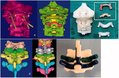
The patients were examined by CT scan before operation and then imaged with 64-row volumetric CT (SOMATOM Sensation 40, Siemens, Malvern, PA) with 5 mm slice thickness. The images were stored in DICOM format and analyzed by the mimics 17.0 (Materialise, Shanghai, China). Then the track and the depth of the screws were designed in 3D format to ensure the screw shaft entered the vertebral body without breaking the pedicle or lamina cortex and only interacted with the appropriate vertebral level and avert vertebral artery, nerve root and spinal cord. Bone data were transferred into a 3D modeling software (Magics 18.0; Materialise, Shanghai, China) after the coordinates of the bone entry points and the trajectory of the screws were determined, and then the templates and 3D models of cervical vertebrae covered with blood vessels and nerves were designed. Then, as designed, the patient-specific templates and 3D bone models were made with photosensitive resin by a 3D printing system () (RS6000; Union Technology Co. Ltd, Shanghai, China). We confirmed the engagement of the templates with the 3D laminae model and screwing emulation before surgery, and then operated on the model to guarantee the accuracy of the screw placement.
Figure 1. The 3D computer model of cervical vertebra and screw insert templates in case1 (A) and case 2 (B).
Four to six screws were inserted in cervical vertebra between C1 and C7 for each patient (the screws in thoracic vertebra is not including), including eight mass screws, two laminar screws and thirty-six pedicle screws. The screws diameter was 3.5 mm and length was 14–32 mm. All 48 screws were inserted with the assistance of individualized 3D printing screw insertion templates. Two mass screws at C1, two laminar screws at C2, two mass screws at C3, two mass screws at C4, two mass screws at C5, two mass screws at C6, and thirty-six pedicle screws at cervical vertebrae ().
Table 1. Master table.
Surgery
The templates were sterilized by a plasma sterilizer in order to be used during the operation. All the operations performed by the same two surgeons. All patients were took prone position and maintained neutral head and neck. The spinous process, the laminar, and the lateral margin of the lateral mass of the target vertebra were adequately exposed. We completely removed the soft tissues from spinous process and the laminae to ensure the templates can tightly combined with surface of the vertebra, and adequately retracted the paraspinal muscles with a retractor. Then we used a high-speed drill to penetrate the cortex and drill the track of the screw along the navigation channel as planned. Finally the screw was carefully inserted along the same track.
Postoperative assessment of screw placement
All the patients underwent CT scans at the screw insertion levels after operation. We then evaluated the accuracy rate by the following classification system used by Kaneyama et al. [Citation15]: Class 1 (accurate), the screw axis deviates less than 2 mm from the planned track; Class 2 (inaccurate), the screw axis deviates 2 mm or more but less than 4 mm; and Class 3 (deviated), the screw axis deviates 4 mm or more. If there is a discrepancy in the class of deviation between the sagittal and axial planes, the worse finding is adopted. Any malposition of the screws in the sagittal and axial planes was evaluated with the grading system as follows: Grade 0: screw is completely within the cortex of the bone structure. Grade 1: a screw was exposed if it broke the cortex of the bone structure, but more than 50% of the screw diameter remained within the bone structure. Grade 2: a pedicle perforation occurred if a screw breached the cortex of the bone structure and more than 50% of the screw diameter was outside the bone structure but there is no clinical sequela. Grade 3: a screw perforates completely outside of the bone structure or there is clinical sequela such as artery or nerve root injury.[Citation16]
Results
The 10 patients with ages ranging from 12 to 72 years (mean 51 years) underwent the 3D printing template-assisted cervical vertebra fusion surgery during the study period. The individualized 3D printing screw insertion templates and 3D bone models were used during the operation. Operation findings proved in accordance with the structure changes shown on the 3D reconstruction and 3D bone models. Only one screw axis greatly deviated from the planned track and breached the cortex of the pedicle because the template was split by rough handling. After this, we inserted the screws under fluoroscopy. The rest of the screws were inserted in the track as preoperative design and the screw axis deviates by less than 2 mm. Postoperative CT confirmed that all the inserted screws were placed accurately (class 1) into the preplanned position except one (class 2), and the mean screw deviation from the planned track was 0.58 ± 0.74 mm (0.0–3.1 mm). In total, 46 of 48 screws (95.8%) were placed completely within the cortex of the pedicle or lamina (grade 0), whereas the other two screws (4.2%) breached the inside wall of pedicle exposing less than half of the screw diameter (grade 1). There were no screws classified as grade 2 or 3 pedicle or lamina breach. The follow-up ranged from 1 to 23 months (mean 10 months). There were no vascular or neurologic complications or injuries. And no infection, broken nails, fracture of bone structure, or screw pullout occurred ().
Table 2. Accuracy and safety of cervical screw insertion with individualized 3D printing screw insertion templates.
Illustrative cases
Case 1
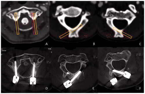
A 12-year-old child who was diagnosed with os odontoideum and atlanto-axial dislocation underwent posterior fusion of the C1–C2. The cervical lateral mass screws were inserted into C1 and laminar screws were inserted into C2. All the screws were placed in the vertebral body without violating the cortex except the left screw of C1. Postoperative CT demonstrated that inside of pedicle was breached and screw was exposed out of pedicle cortex. It was our first time using the template; we had no prior experience with this method. There were no symptoms of blood vessel or nerve injury. Postoperative CT demonstrated that the trajectory deviations were 3.1 mm at the left C1, which broke the inside wall of pedicle (grade 1), 0.3 mm at the right C1 (D), 0.2 mm at the left C2 (E) and 0.5 mm at the right C2 (F) ().
Figure 2. The planned screw trajectories of among C1 (A), left C2 (B), and right C2 (C). Postoperative CT demonstrated that the trajectory deviations were 3.1 mm at the left C1, which broke the inside wall of lateral mass (grade 1), 0.3 mm at the right C1 (D), 0.2 mm at the left C2 (E), and 0.5 mm at the right C2 (F).
Case 2
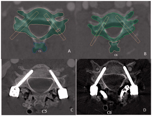
A 46-year-old male who was diagnosed with C7 solitary plasmacytoma underwent C7 focal cleaning, prosthetic lamina replacement, internal fixation of C5,C6-T2,T3 in posterior vertebral pedicles, and anterior 3D printing prosthetic vertebra replacement bone grafting and fusion. The cervical pedicle screws were inserted into C5, C6, T2, and T3. All the screws were placed in the vertebral body without violating the cortex of pedicle and there were no symptoms of blood vessel or nerve injury. Postoperative CT revealed that the trajectory deviations were 0.2 mm at the left C5 pedicle, 0.3 mm at the right C5, 0.1 mm at right C6, and 0.4 mm at the left C6. They were accurately at the planned location (class 1) and within the pedicle cortex (grade 0) ().
Figure 3. The planned screw trajectories of C1 (A) and C2 (B). Postoperative CT demonstrated that the trajectory deviations were 0.3 mm at the left C5 pedicle, 0.2 mm at the right C5(C), 0.1 mm at the right C6, and 0.4 mm at the left C6 (D). They were accurately at the planned location (class 1) and within the pedicle cortex (grade 0) (the mask in A and B reveals the C5 and C6 after reduction as we simulate on the computer).
Discussion
The use of lateral mass screws, lamina screws, and pedicle screws is proven to be the safe and effective method of posterior fixation for the cervical vertebra.[Citation17–19] Because of the anatomic variation of the posterior cervical vertebra and its adjacent structure, the operator tasked with screw insertion must be experienced and skilled. Many prospective and retrospective studies have already demonstrated the challenges of screw placement in the cervical spine, including the risk of neurovascular injury and spinal cord injury.[Citation12,Citation20] The screws inserted in different parts of the vertebra can cause various complications.[Citation21] The anatomic structure specificity of each cervical vertebra causes many difficulties in quantitative analysis. Since many studies have confirmed that anatomic landmarks can be helpful in the placement of screws in cervical vertebra.[Citation22] Goffin et al. [Citation23] first described the three-dimensional computer tomography-based personalized drill guide for posterior cervical fusion at C1–C2, which outlines a new strategy for improving the accuracy of screw insertion. Taku et al. [Citation15] developed SGT make screws insertion templates more accurate. But it also needs more material because it consists of three parts and it also needs more time and operation steps during the operation. Our template is comparatively concise but less accurate and is easier to be used in common institutions.
Based on the experience, we have used screw guide templates in spine and other positions, we think that the individualized 3D printing templates has the potential for wide applications in municipal hospitals which are inexperienced and perform a relatively small number of surgeries. The individualized 3D printing screw insertion template has obvious advantages over the current technology. First of all, it is easy to use by simply attaching to the laminae, which can significantly reduce operation time and the risk of infection. Application of screws insertion templates provide a simple way to insert screws even if the operator without much operative experience. It can significantly raise the accuracy rate and minimize injuries to major nerves and blood vessels. Second, using the templates during the operation can reduce the intraoperative real-time fluoroscopy frequency by a large margin, so that the doctor and patients can be less expose to the radiation. Third, the template is also a safe instrument because the material we used has the properties of high melting point, low brittleness, and high toughness. In addition, we used Kirschner wires to drill the track of the screw in the operation. In this condition, the inside wall of template and the surface of Kirschner wires are smooth. These properties and features make the templates difficult to bend, break or even create debris. What is important is that this cost-effective method can be widely applied in basic hospitals without the need of other auxiliary. Currently, the cost of the template is relatively high, but this problem will be readily solved with the progress of materials and technology involved.
There are a few problems that need to be addressed. First, to ensure the perfect insertion of screws, soft tissues should be completely removed so that the templates can be completely attached to the posterior surface of the spinous process, vertebral plate and zygopophysis of the target vertebra. This method will increase intraoperative blood loss and operation time. Second, in the process of operation, any slight relative activity will lead to deviation of the screw axis.
We have some experiences related to the use of the individualized 3D printing screw insertion templates to share: first, it is very important to drill deep enough (more than two-thirds of the screw length) to ensure the screw will not change its pathway in deeper. Second, the soft tissue attached to the spinous process and the laminae should be completely removed as cleanly as possible, otherwise the soft tissue will be involved into the cause the screws to diverging in directions of the screws. Third, in the case that the normal anatomy of the cervical spine was destroyed seriously, it is better not to blindly follow the path outlined by the templates. It is important to note that simulation before operation may be different from the practice.
There are also many sources of error in the process of design and production of 3D printing templates, including the transformation of the data in different software in the design process, the accuracy of the 3D printers, the probable deformation after sterilization, and so on. Violent actions during the operation may also lead to deformation of the template. In fact, the first time when we used the template, a large deviation from the planned track occurred because the operator lacked experience and exerted excessive force while drilling. For this reason, surgeons should partially rely on their experience and not exclusively on the templates during operation. Lastly, the design and printing of the templates requires time, so the individualized 3D printing templates cannot be applied to emergency operation. Precisely because of these reasons, future research should focus on how to produce 3D templates that are more reasonable and effective than before. In addition, 3D printing templates are currently used mainly in the laboratory and there have only been a small amount of clinical studies. More randomized controlled trails are needed on this issue to provide more evidence.
Conclusion
This study verified the safety and the accuracy of the individualized 3D printing screw insertion template in cervical spine as a kind of intraoperative screw navigation. This individualized 3D printing screw insertion template was user-friendly, moderate cost, and enabled a radiation-free cervical screw insertion.
Disclosure statement
The authors report that they have no conflicts of interest.
References
- Dunlap BJ, Karaikovic EE, Park HS, et al. Load sharing properties of cervical pedicle screw-rod constructs versus lateral mass screw-rod constructs. Eur Spine J. 2010;19:803–808.
- Kothe R, Ruther W, Schneider E, et al. Biomechanical analysis of transpedicular screw fixation in the subaxial cervical spine. Spine (Phila PA 1976). 2004;29:1869–1875.
- Jones EL, Heller JG, Silcox DH, et al. Cervical pedicle screws versus lateral mass screws. Anatomic feasibility and biomechanical comparison. Spine (Phila PA 1976). 1997;22:977–982.
- Ebraheim NA, Xu R, Knight T, et al. Morphometric evaluation of lower cervical pedicle and its projection. Spine (Phila PA 1976). 1997;22:1–6.
- Karaikovic EE, Kunakornsawat S, Daubs MD, et al. Surgical anatomy of the cervical pedicles: landmarks for posterior cervical pedicle entrance localization. J Spinal Disord. 2000;13:63–72.
- Abumi K, Shono Y, Ito M, et al. Complications of pedicle screw fixation in reconstructive surgery of the cervical spine. Spine (Phila PA 1976). 2000;25:962–969.
- Park JH, Jeon SR, Roh SW, et al. The safety and accuracy of freehand pedicle screw placement in the subaxial cervical spine: a series of 45 consecutive patients. Spine (Phila PA 1976). 2014;39:280–285.
- Sciubba DM, Noggle JC, Vellimana AK, et al. Radiographic and clinical evaluation of free-hand placement of C-2 pedicle screws. Clinical article. J Neurosurg Spine. 2009;11:15–22.
- Tian W, Liu Y, Zheng S, et al. Accuracy of lower cervical pedicle screw placement with assistance of distinct navigation systems: a human cadaveric study. Eur Spine J. 2013;22:148–155.
- Ito H, Neo M, Yoshida M, et al. Efficacy of computer-assisted pedicle screw insertion for cervical instability in RA patients. Rheumatol Int. 2007;27:567–574.
- Mason A, Paulsen R, Babuska JM, et al. The accuracy of pedicle screw placement using intraoperative image guidance systems. J Neurosurg Spine. 2014;20:196–203.
- Yoshimoto H, Sato S, Hyakumachi T, et al. Spinal reconstruction using a cervical pedicle screw system. Clin Orthop Relat Res. 2005;431:111–119.
- Devito DP, Kaplan L, Dietl R, et al. Clinical acceptance and accuracy assessment of spinal implants guided with SpineAssist surgical robot: retrospective study. Spine (Phila PA 1976). 2010;35:2109–2115.
- Zausinger S, Scheder B, Uhl E, et al. Intraoperative computed tomography with integrated navigation system in spinal stabilizations. Spine (Phila Pa 1976). 2009;34:2919–2926.
- Kaneyama S, Sugawara T, Sumi M. Safe and accurate midcervical pedicle screw insertion procedure with the patient-specific screw guide template system. Spine (Phila Pa 1976). 2015;40:E341–E348.
- Yukawa Y, Kato F, Ito K, et al. Placement and complications of cervical pedicle screws in 144 cervical trauma patients using pedicle axis view techniques by fluoroscope. Eur Spine J. 2009;18:1293–1299.
- Cassinelli EH, Lee M, Skalak A, et al. Anatomic considerations for the placement of C2 laminar screws. Spine (Phila PA 1976). 2006;31:2767–2771.
- Gorek J, Acaroglu E, Berven S, et al. Constructs incorporating intralaminar C2 screws provide rigid stability for atlantoaxial fixation. Spine (Phila PA 1976). 2005;30:1513–1518.
- Reddy C, Ingalhalikar AV, Channon S, et al. In vitro biomechanical comparison of transpedicular versus translaminar C-2 screw fixation in C2-3 instrumentation. J Neurosurg Spine. 2007;7:414–418.
- Kast E, Mohr K, Richter HP, et al. Complications of transpedicular screw fixation in the cervical spine. Eur Spine J. 2006;15:327–334.
- Ebraheim N, Rollins JJ, Xu R, et al. Anatomic consideration of C2 pedicle screw placement. Spine (Phila PA 1976). 1996;21:691–695.
- Karaikovic EE, Kunakornsawat S, Daubs MD, et al. Surgical anatomy of the cervical pedicles: landmarks for posterior cervical pedicle entrance localization. J Spinal Disord. 2000;13:63–72.
- Goffin J, Van Brussel K, Martens K, et al. Three-dimensional computed tomography-based, personalized drill guide for posterior cervical stabilization at C1-C2. Spine (Phila PA 1976). 2001;26:1343–1347.