
Abstract
Pedicle screws are an established method for spinal segmental fixation. To pursue high accuracy and minimally invasive, various different guidance techniques have developed. However, the preoperative screw position plans are determined by manual selection which demands complex operations and costs a lot of time. In addition, the current paths planning only consider the position, without taking the postoperative screws retention into consideration. In order to solve the problems, a new method was proposed to plan the lumbar pedicle screw placement automatically. Firstly, identify pedicle area and establish initial path based on the current vertebrae segmentation technology. After that, optimize path via the improved boundary limited Nelder–Mead simplex algorithm, and get the highest firmness path in theory. We considered that both the accuracy of position and the firmness of postoperative screws, achieved a fully automatic optimal path planning, which can effectively assist operators, improve the firmness of screw placement.
1. Introduction
Spinal fusion is typically performed for the treatment of a number of cases such as degenerative disease, trauma or spinal deformity. The procedure for pedicle screw placement is complex and technically demanding with a steep learning curve. Perforation of the pedicle wall during screw placement could happen and cause severe complications (vascular or nerve damage, reduced stability of the bone). Nowadays, patients are more critical to medical treatment. Different supporting techniques exist to improve the accuracy and reduce the invasive of screw placement e.g. fluoroscopy, CT guidance or percutaneous robotic guidance.
All the techniques need to analyze the preoperative CT images and plan the screw position. Optimal position needs to meet the following conditions: Perforation of the pedicle wall shall not happen; the entrance angle of screw shall be changed according to the angle of pedicle; perforation of cortical bone outside the vertebrae is not allowed; there is enough bone tissue can provide retention to ensure the firmness after the screw enters into. At present, optimal positions and orientations of the screws are determined by manual selection. Operators spend a long time to shift the angle of view to determine the position of screw on different sections of CT images,[Citation1] and without considering if the bone quantity can provide enough retention for the pedicle screw.
Against the above-mentioned problems, the article proposed the automatic lumbar pedicle screw path planning method based on preoperative CT images.
Figure 1. The schematic diagram of the algorithm for removing lumbar vertebrae little joint.
2. Methods
The method is divided into three steps as follows to achieve automatic path planning for lumbar pedicle screw path. Firstly, segmentation of an individual vertebral and set up of an individual coordinate system; Secondly, identify pedicle area and establish initial path; Thirdly, calculate bone density in the screws area which would be used as the objective function, and then find an optimal path via Nelder–Mead Simplex Algorithm.
Segmentation of an individual vertebrae, and establish correction direction and correction plane
Before the segmentation of an individual lumbar vertebra is carried out, the whole spine must be segmented first. We used the whole bone segmentation algorithm of automatic threshold. The gray level histogram was used to fit two crossed Gauss curves (soft tissue and bone); The crossing point is the binarization threshold. After binarization processing and hole filling, we could obtain the segmentation results of the whole spine. The segmentation method is mature, so it won’t be repeated here.
The spine of human beings is naturally curved and has certain mobility, so the segmentation of individual spine and the correction of spatial position shall be performed. Therefore, we need find the correction direction and correction plane of an individual vertebra.
We use ALSM [Citation2] method to find the correction direction. At first, small joint parts of the vertebrae was segregated and ignored temporarily to avoid any interference.
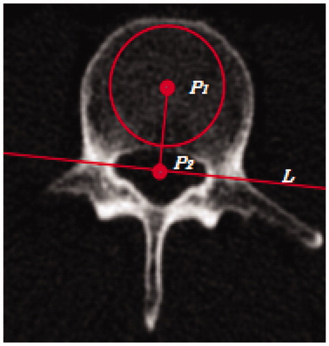
A maximal circle that can be put in the segmentation result shall be found layer-by-layer on the cross-sectional images. The center of the circle P1 is taken as the center of vertebral part; Closure cavity can be found on the cross section, and the centroid of the closure cavity P2 is taken as the center of spinal canal; P1 is connected to P2, and line L is set perpendicular to P1P2 through P2. Hence, the plane is divided into two parts, and P1P2 is the correction direction for the vertebrae as .
For the following configuration of auxiliary segmentation plane for the vertebrae, only vertebral part is selected. According to the morphologic characteristics of the vertebrae, suitable structural element objects shall be selected to carry out three-dimensional close operations for the images, thus to connect the adjacent vertebrae. Compared to the original images, all newly added points as the auxiliary points locate between two sections of the vertebrae. A connected region is formed between every two sections of the vertebrae as in .
Figure 2. Distribution of the auxiliary points.
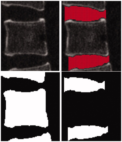
These auxiliary points in each connected region are taken as given points, and a plane can be obtained by regressing auxiliary points with least squares method. Taking one section of the vertebrae as an example, two planes A and B can be fitted as , which are the auxiliary segmentation planes for the vertebra.
(1)
(2)
Figure 3. The auxiliary segmentation plane and the correction plane of the vertebra.
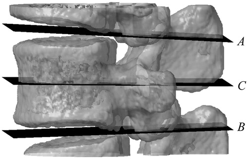
As the mean value of the two planes in all directions, plane C can be set up. Plane C is the correction plane for the vertebra as .
(3)
The area between plane A and plane B is the segmentation result of an individual spine that is the basic for the subsequent processing.
Identify pedicle area and establish central path of pedicle
The position of the screw must be placed in the pedicle, and pass through the center of the pedicle as much as possible. Therefore, the key of path planning is to identify pedicle area. The location of the pedicle is in the middle position of the vertebra; the pedicle joints to vertebra, zygapophysis and vertebral plate; besides, it is short and stout; and its shape is an arch.
Refer to , we get line L. Then, we need to made a plane L′ which is perpendicular to plane C and through line L. The pedicle area is located around plane L′. A certain amount of sections and segmentation data are set at the front and rear position of plane L′ along the correction direction. On each section, there are one or several connected regions. Then filter each connected region layer-by-layer according to the anatomical features of pedicle. The specific steps are as follows.
Figure 4. The recognized pedicle area with the largest inner circle.
Detect whether the connected region is close to the boundary, and get rid of those connected regions adjacent to the boundary.
Estimate the size of connected regions, and get rid of extremely big or small regions.
Find the largest inscribed circle in each connected region. Discard regions with extremely small radius, thus the non-arch regions can be filtered.
Judge that whether the rest of the connected regions are continuous in three-dimensional direction, and discard the discontinuous regions.
Before performing step b, we need to set a range of pedicle section area that is significant sexual differences and area differences.[Citation3] Therefore, parameters need to be chose according to different situations. With the above steps of processing, the connected regions gained are pedicle as .
The next is to establish the center path of pedicle. The center of each inscribed circle p1 … pn can be obtained, so we take the point as the center of pedicle, and then pc(xc,yc,zc) is taken as the designated-point of the path. The fitting of all centers with least squares method can be performed to gain line l′. During the process, what we gained is the deviation angle of the pedicle relative to the vertebra.
According to current planning principles, the entrance angle of the screw shall be parallel to the end-plate of the adjacent vertebra on the sagittal sections. Due to the structure that pedicle, vertebra, zygopophysis and vertebral plate are connected with each other, the central position gained will be located at upper or lower position, thus causing the direction deviation of l′ in the jointed area. Hence, l′ needs to be adjusted. Through l′ make the projection to plane C, get l0 which go through pc and parallel to plane C. l0 can be taken as the initial path of pedicle as .
(4)
Figure 5. Adjust the path to make it is parallel to the correction plane.
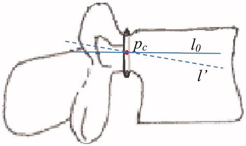
In above, m0, n0, p0 is the direction vector of line l0.
The same processing can be used for the other side pedicle. The result is as .
Figure 6. The result of initial path recognition.
The optimal path planning
For the path planning, we must ensure that the path go through the center of pedicle as much as possible and the firmness. We hope that the spine could provide the maximum holding force to screws. CT value has linear relationship with bone density.[Citation4,Citation5] There are many papers have proven the exponential relationship between the bone mineral density and the Young’s modulus of bone tissue.[Citation6–8]
Without taking the type of screws into consideration, the screw path should be as long as possible, and bone density around the path would reach the maximum.
This is a non-differentiable nonlinear optimization problem with restricted boundary. Objective function is f(x). Total CT value at the area around path l is calculated. Initial value is the central path l0 gained in the last step. S represents permitted variable range, which can be expressed:
In which x= (m, n), m, n, represent two direction vectors of path.
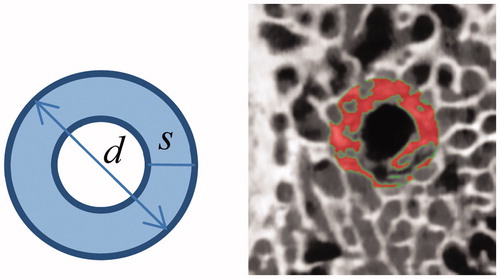
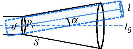
Two problems need to be considered for the computational domain of objective function: The first problem is the section area of the path. is a μCT image that shows violent removal of pedicle screw from the bone tissue. We can see that the damaged bone tissue is mainly at the occlusion area of the screw thread. Hence, we consider that the holding force of the vertebra mainly depends on the bone density in the occlusion area of the screw thread. So we calculate total CT value in the area. shows the section of the screw passing through the bone tissue, in which, d represents the diameter of the screw; s represents the width of the screw thread; the shaded area needs to be calculated.
Figure 7. A μCT image shows violent removal of pedicle screw from the bone tissue.
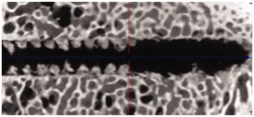
Figure 8. The section area of the path which needs to be calculated.
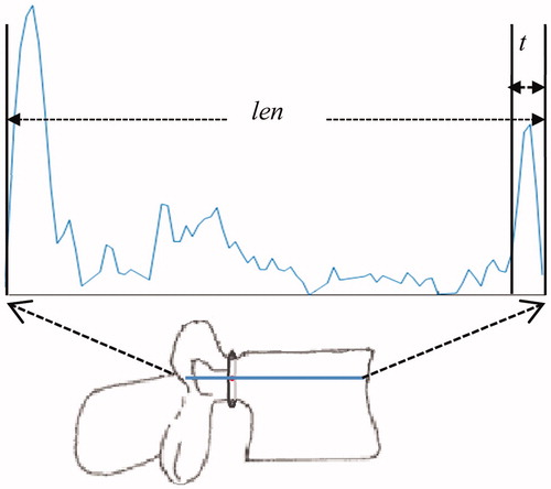
The second problem is the cutoff point of the path. The screw cannot pass through the cortical bone of the vertebra and must stop at the front of it. Total perforation length through the spine is len. The distance from the vertebra boundary is defined as t which should a little larger than the thickness of cortical bone. Therefore, the length of the path is len–t. In practical operation, different length of the screws causes different t ().
Figure 9. The alter of CT value on the path area and the length of the screws through vertebra.
The clinical doctors consider that the variable range of screw path is small. In order to ensure the path after the limit optimization is in a permitted variation range, we only need to restrict the vertebra area. At first, we divide the spine into two parts. We take section plane M with pc as the segmentation plane, and take the side where the vertebra is located as the restricted area (). Then, with pc as the center, we assume that the angle of variable path based on the central path l0 is ≤α°. Variable range S can be expressed as , in which, d represents the diameter of the screw. All points beyond inner side of S area are set zero. Hence, the optimized result will be in the restricted area.
Figure 10. Take plane Mas the segmentation plane to restrict optimization area.
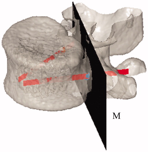
Figure 11. Variable optimization area S.
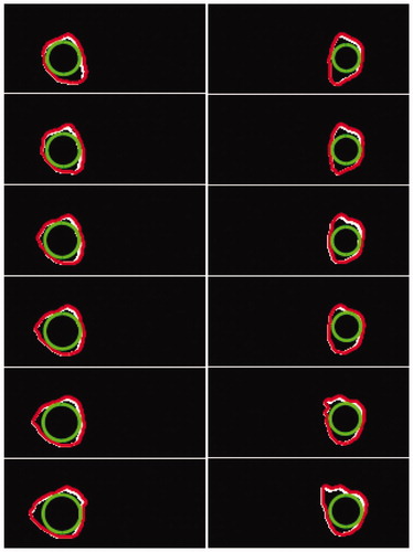
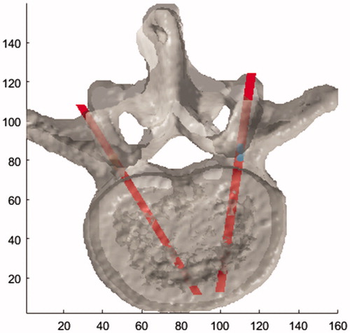
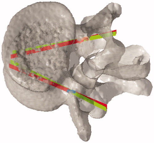
Then we made this problem to become an unrestricted non-differentiable nonlinear optimization problem. We use the Nelder–Mead simplex algorithm to carry out optimization solution. Take L3 lumbar vertebrae data as example, in , the red lines represent initial path; the green lines represent optimization path.
Figure 12. The comparison between initial path and optimization path.
3. Analysis and discussion
The method proposed is mainly applied to identify the pedicle and screws path. Since the shape of thoracic vertebrae and cervical vertebra is different to the lumbar vertebrae, this method can not be used.
Due to the limited data, we have tested nine sets of L3–L5 CT data. The CT data we selected were 20–40 years old adult male, and the estimation of pedicle area was according to the research of Ma Yan et al. [Citation8] With this method, it all identified the pedicle area and central path successfully, and get the optimization path. In addition, the outcomes have been proved available by surgery spinal doctor.
If manual planning rather than automatic path planning is used for such cases like damaged spine, the information of bone mass around real-time feedback path stated in the article can also be used to provide reference for doctors, thus to select a path with larger bone quantity to ensure the firmness of the screws.
For the assessment of the firmness, the article is on a basis of CT value. Actually, there are many influencing factors of the holding force, for instances, the type of the screw and the screw thread, bone trabecular structure. Thus, the assessment simply based on CT value cannot achieve quantitative analysis. If biomechanical analysis could be co-used, more accurate assessment could be provided for the firmness of the screw path.
4. Conclusion
The method we proposed can identify the pedicle area, and automatically plan the optimization path for screw placement without any manual intervention, with taking both screw position and bone quantity in consideration, which can get the most firmness path, and greatly reduce the workload of doctors.
Disclosure statement
The authors report no conflicts of interest. The authors alone are responsible for the content and writing of this article.
References
- Ungi T, Moult E, Schwab JH, et al. Tracked ultrasound snapshots in percutaneous pedicle screw placement navigation: a feasibility study. Clin Orthopaed Related Res. 2013;471:4047–4055.
- Kai Z, Zhiqiong W, Yan K, et al. A highly automatic lumbar vertebrae segmentation method using 3D CT data. J Northeastern Univ Naturalence. 2011;32:340–343.
- Yan M, Yan L, Wei M, et al. Anatomic measurement of the pedicle of vertebral arch of the adult in north China area and its clinical significance. Chin J Clin Anat. 2009;27:295–298.
- Xiaozhao C, Quanhai F, Zhiyong S, et al. QCT method based on liquid phantoms for jaw bone density measurement using Oral CT. J Northeastern Univ Naturalence. 2015;36:636–640.
- Cody D, Gross G, Hou F, et al. Femoral strength is better predicted by finite element models than QCT and DXA. J Biomech. 1999;32:1013–1020.
- Rho JY, Hobatho MC, Ashman RB, et al. Relations of mechanical properties to density and CT numbers in human bone. Med Eng Phys. 1995;17:347–355.
- Keller TS. Predicting the compressive mechanical behavior of bone. J Biomech. 1994;27:1159–l168.
- Carter DR, Hayes WC. The compressive behavior of bone as a two-phase porous structure. J Bone Joint Surg. 1977;59:954–962.