
Abstract
Magnetic induction measurement (MIM) is a promising technique for biomedical applications in craniocerebral disease detection and monitoring. For the purposes of the MIM simulation, a human head model with real anatomic structure is required. However, nearly anatomically realistic models used in the MIM simulations are discretized using tetrahedral elements of subsequent finite elements method computation. The head model supplied by the Third Military Medical University (TMMU) is currently the only model suitable for hexahedral discretization and finite difference/integral computation. This model has nonetheless number of defects. In order to deal with these, we construct an improved 10-tissue human head model with real anatomical structures and hexahedral discretization features. In this paper, the operation and optimization methods used to construct for the new head model are presented and discussed in detail. We use the 10-tissue head model to conduct the time sensitivity simulation of the magnetic induction sensor which was described in our previous publication and compare the simulation data with those based on the TMMU’s head model. The result shows that the new head model has a higher time sensitivity, meaning better performance in the MIM simulation.
1. Introduction
Magnetic induction measurement (MIM) is an attractive technique with the prospect of detecting intracerebral hemorrhage (ICH) and brain edema.[Citation1,Citation2] As a powerful and efficient procedure, simulation is frequently used to test the performance of MIM systems. Therefore, it is vital to consider the object used to imitate the human head in the MIM simulation. In many publications, however, some simple shapes (e.g. sphere and cylinder) are modeled as the human head. These geometries are much different from the real human head, and hence the contributions of related study results and conclusions are limited. There is a need to construct a human head model with real anatomic structures for a realistic MIM simulation.
The first report of applying an anatomically realistic model in the MIM simulation was by Merwa et al. [Citation3] They used 150 human head images from the Visible Man Human Project database and processed them with a custom-made software. The complete model incorporates brain white matter, brain grey matter, third ventricle, and lateral ventricle as structures. Zolgharni et al. [Citation4] utilized a finite element head model to conduct a simulation of ICH measurement. The head model which is developed from human head MRI data comprised 12 different tissues: muscle, skull, CSF, brain grey matter, brain white matter, ventricle, spinal cord, optic nerve, eyeball, nasal cavity, ear canal, and olfactory organ. Dekdouk et al. [Citation5,Citation6] used the same 12 tissues head model to solve the forward problem in magnetic induction tomography, and a similar but simplified 7 tissues head model which contains scalp, skull, CSF, brain grey matter, brain white matter, spinal/optic nerve, and eyeball is also been used in their research. He et al. [Citation7] used segmented MRI data to build a finite element brain model for the forward problem simulation in magnetic induction tomography.
Unlike previous anatomically realistic models which should only be discretized into tetrahedral elements and then computed by the finite element method, the head model provided by the Third Military Medical University is suitable for hexahedral discretization which is the first of its kind employed in the MIM simulation.[Citation8] The TMMU’s head model contains seven tissues, including scalp, skull, CSF, brain, optic nerve, eyeball, and blood. Although the head model can be computed by the finite difference/integral methods, a few drawbacks nevertheless still exist such as: (i) too few tissues, (ii) inconvenient to model the hemorrhage area due to the complicated CSF structure with most of its boundaries being inside the brain structure, and (iii) large tissue structure overlaps which can be source of computation inaccuracies. To settle these difficulties, we propose an improved human head model. The operation and optimization methods for the head model are presented and discussed in detail. Using the new head model, the time sensitivity simulation of the magnetic induction sensor described in our previous publication [Citation8] is conducted in CST, and the corresponding results are compared with those obtained by the TMMU’s head model.
2. Methods
The following software tools were used for model construction: Photoshop (Adobe Systems, USA), CorelDraw (Corel, Canada), AutoCAD (Autodesk, USA), and CST (CST, Germany). shows the flow chart of constructing human head model.
Figure 1. Flow chart of constructing human head model.
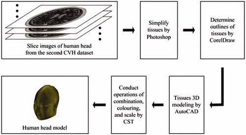
In total, 200 slice images of human head were obtained from the second Chinese Visible Human (CVH) dataset.[Citation9] As the dataset is obtained from a cadaver without chronic disease or visible lesions, it naturally contains numerous tissues. Some tissues have too smaller structures to influence the simulation outcome, so the priority for head model construction is to choose and set tissues reasonably. We treat each image by ignoring small tissues and combining tissues with close electromagnetic parameters by Photoshop, and eventually determine skin, muscle, skull, blood, brain, cerebellum, eyeball, optic nerve, tongue, and tooth as the tissues in the head model. shows the simplified and equivalent details for head model construction.
Table 1. Simplified and equivalent details for head model construction.
The images generated from Photoshop are raster images, which should be converted into vector images so as to be treated in AutoCAD. CorelDraw is used to achieve this conversion. We use the trace function in CorelDraw to get the contours of raster images, and then save the images as dwg files which are vector images and can be opened by AutoCAD.
The steps for 3D modeling in AutoCAD are illustrated as follows. First, we open each dwg file and stretch its inner model. The stretching distance should be equal to the smallest mesh length which can be measured in AutoCAD. Second, for all the files we choose one tissue as modeling object and delete other tissues. It is noted that different tissues may overlap with each other or tissues with the same type might be labelled differently. These two problems can be solved by using the subtraction and union function in AutoCAD to distinguish different tissues and combine tissues with the same type. Finally, we export each layer model as sat file in order that it can be imported into CST for further treatment.
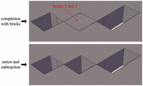
Some distortions (see ) might appear after treatment by CorelDraw, and they can be eliminated in AutoCAD. There are two types of distortions: sharp corner missing and sharp corner deformation, as shown in . For the sharp corner missing, it can be repaired by building a brick with the missing section as its diagonal plane and then performing the operation of union, as is shown in . For the sharp corner deformation, it can be repaired by completing two bricks at the distortion zone and then performing the operations of union and subtraction in turn, as is shown in .
Figure 2. Images after treatment by Photoshop and CorelDraw.
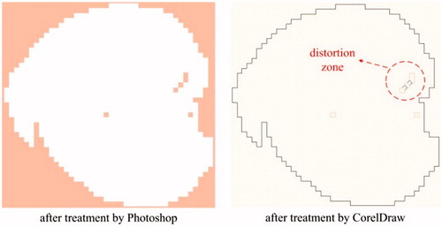
Figure 3. Example for sharp corner missing and deformation.
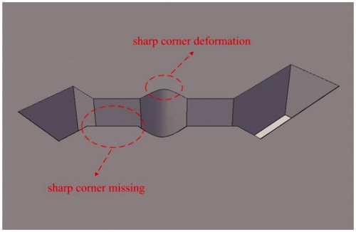
Figure 4. Method of sharp corner missing eliminated.
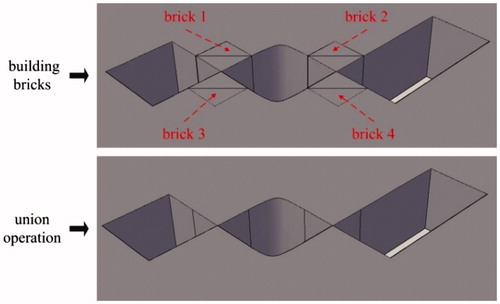
Figure 5. Method of sharp corner deformation eliminated.
3. Results
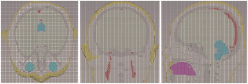
After all the sat files for one specified tissue are imported into CST, we can combine them and build the entire tissue model by setting relative translation, using Boolean operations, and exporting the entire tissue model as a sat file. For each tissue chosen in AutoCAD, we can always obtain its entire sat file in this way. Then we can import and combine the 10 entire sat files in CST, color different tissues with different colors, and carry out the scale operation to make the smallest mesh length of entire model to be the unit scale. Finally, the complete 10-tissue head model can be exported as a sat file. The head model volume is about 3900 cm3, with a resolution of 1 mm3. Related physical parameters can be assigned to each tissue in the head model, according to the existing literatures.[Citation10–14] The total file for the head model is 2.76 GB, and about 8.6 GB of computer memory can be occupied when the head model is imported into CST. shows the model assembled from 10 tissue types; shows the whole and cross-section views of the head model, and shows the mesh view of 10-tissue head model in CST.
Figure 6. Model assembled from 10 tissue types.
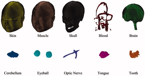
Figure 7. Whole and cross-section views of the head model.
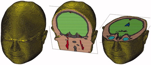
Figure 8. Mesh view of 10-tissue human head in CST.
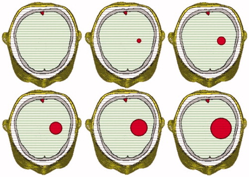
ICH usually appears in the left or right hemisphere of the brain and above the eyeballs level. For salvageable ICH patients, the amount of bleeding in their brain ranges from 0 to 70 ml, with a moderate value of about 20 ml. When the amount is over 30 ml, it is regarded as high-volume ICH. Our 10-tissue head model can be used to simulate different ICH conditions easily by adding a sphere models with different radii, as is shown in .
Figure 9. 10-tissue head model with different sphere models to simulate different levels of ICH (from normal case to severe case).
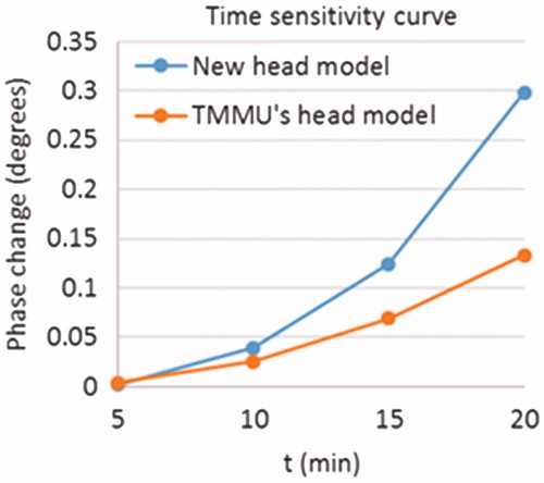
We test the performance of the improved 10-tissue head model using our novel magnetic induction sensor which was described in the study of Zhang et al. [Citation8]. The new head model and the TMMU’s head model are both calculated in CST, and their time sensitivity curves are studied. The hemorrhage occurs in the left hemisphere of the brain, and its volume can be increased with its radius. The diffusion rate of hemorrhage is 1 mm per minute in all directions. The frequency and amplitude of excitation current are 40 MHz and 1 A, respectively. shows the simulation results. From the figure, we can see that the amplitude of the time sensitivity curve for the new head model is much higher than that for the TMMU’s head model. This is reasonable because the complicated structures in the TMMU’s head model can prevent the phase change from increasing. As the volume of hemorrhage increases, the hemorrhage model will overlap with the CSF structure which has the largest conductivity value in the TMMU’s head model. Therefore, the phase change for the TMMU’s head model can be reduced due to parts of the CSF structure being removed. This means that the head model is much more practical for the MIM simulation.
Figure 10. Simulation results of time sensitivity in CST.
4. Conclusions
We constructed an improved 10-tissue human head model with real anatomical structures based on hexahedral discretization. Compared with the TMMU’s head model, our new head model has more rational tissue quantities and structures, and solves the problems caused by the overlap of the hemorrhage and tissue areas. The file size of our head model is moderate and acceptable, and it can be used to conduct the MIM simulation on a normal workstation (32 GB physical memory). We also conducted the time sensitivity test on magnetic induction sensor in CST by comparing our new head model with the TMMU’s head model. The result shows that our head model can overcome the shortcomings of the TMMU’s head model. Other aspects of biomedical simulation such as specific absorption rate and thermal response calculations can also be considered by using this proposed head model.
Acknowledgements
The authors would like to thank the Associate Professor X. Ning from the Third Military Medical University and the Engineer H. Li from the No. 161 Hospital of PLA for helpful discussions, and are also grateful to the Third Military Medical University for providing the data source of head model.
Disclosure statement
The authors report no conflicts of interest. The authors alone are responsible for the content and writing of this article.
Funding
This work was supported by the Innovation Fund for Graduates from the Hunan Province Education Office [grant No. CX2013B011] and the Innovation Fund for Doctoral Candidates from the National University of Defense Technology [grant No. B130205].
8. References
- Scharfetter H, Casañas R, Rosell J. Biological tissue characterization by magnetic induction spectroscopy (MIS): requirements and limitations. IEEE Trans Biomed Eng. 2003;50:870–880.
- Jin G, Sun J, Qin M, et al. A new method for detecting cerebral hemorrhage in rabbits by magnetic inductive phase shift. Biosens Bioelectron. 2014;52:374–378.
- Merwa R, Hollaus K, Biró O, et al. Detection of brain oedema using magnetic induction tomography: a feasibility study of the likely sensitivity and detectability. Physiol Meas. 2004;25:347–354.
- Zolgharni M, Ledger PD, Griffiths H. Forward modelling of magnetic induction tomography: a sensitivity study for detecting haemorrhagic cerebral stroke. Med Biol Eng Comput. 2009;47:1301–1313.
- Dekdouk B, Yin W, Ktistis C, et al. A method to solve the forward problem in magnetic induction tomography based on the weakly coupled field approximation. IEEE Trans Biomed Eng. 2010;57:914–921.
- Dekdouk B, Yin W, Ktistis C, et al. Assessing the feasibility of detecting a hemorrhagic type stroke using a 16 channel magnetic induction system. J Phys Conf Ser. 2010;224:012047.
- He W, Song X, Xu Z, et al. Magnetic induction tomography: simulation study on the forward problem. Lect Notes Comput Sci. 2010;6330:113–121.
- Zhang Z, Liu P, Zhou D, et al. Intracerebral hemorrhage (ICH) evaluation with a novel magnetic induction sensor: a preliminary study using the Chinese head model. Biomed Mater Eng. 2014;24:3579–3587.
- Zhang S, Heng P, Liu Z, et al. Creation of the Chinese visible human data set. Anat Rec B New Anat. 2003;275:190–195.
- DeMarco SC, Lazzi G, Liu W, et al. Computed SAR and thermal elevation in a 0.25-mm 2-D model of the human eye and head in response to an implanted retinal stimulator—part I: models and methods. IEEE Trans Antennas Propag. 2003;51:2274–2285.
- Hirata A. Temperature increase in human eyes due to near-field and far-field exposures at 900 MHz, 1.5 GHz, and 1.9 GHz. IEEE Trans Electromagn Compat. 2005;47:68–76.
- Makris N, Angelone L, Tulloch S, et al. MRI-based anatomical model of the human head for specific absorption rate mapping. Med Biol Eng Comput. 2008;46:1239–1251.
- Collins CM, Liu W, Wang J, et al. Temperature and SAR calculations for a human head within volume and surface coils at 64 and 300 MHz. J Magn Reson Imaging. 2004;19:650–656.
- Bernardi P, Cavagnaro M, Pisa S, et al. Specific absorption rate and temperature elevation in a subject exposed in the far-field of radio-frequency sources operating in the 10–900-MHz range. IEEE Trans Biomed Eng. 2003;50:295–304.