
Abstract
Recently, people have paid more attention to skin that seems determine age, beauty and appearance. In particular, acne scar that tends to grow in young generation. Synthetic model can help to prevent them to care beforehand. This study proposes a representation for acne scars and general scars using a height map and an improved subsurface scattering color model. In consideration of the geometric properties of acne scars classified into ice pick, rolling and boxcar, a height map is used. Where the improved subsurface scattering color model and shading are applied, convenient system interfaces are provided to represent wounds and scars conveniently. An automation function is added for the user to control the height map, as well as four shading functions comparable with the shading function proposed in this study. In addition, a user study is performed to validate the proposed method.
1. Introduction
Human skin is an extremely important factor that affects the assessment of a person’s looks. Depending on the facial skin, a person can have a different look or feel. The fact that an external observation of a person’s skin can provide indications of that person’s age proves that the skin plays an importance role on appearance. Regardless of gender and age, concerns regarding the skin grow continuously, and for such reasons, concern over skin care also continues to grow. There have been many skin-related studies: medical studies on how the skin affects the human body;[Citation1,Citation2] cosmetic studies in terms of skin care;[Citation3,Citation4] and technical studies for computer representation.[Citation5,Citation6] Further, studies on the representation of wounds and scars [Citation7,Citation8] are ongoing. In fact, in the computer graphics field, most of the existing studies are concerned with realistic skin rendering. Most of the researchers are mainly interested in rendering that reflects skin translucency, and in skin representations that reflect the skin physiological characteristics. Considering how a person’s skin affects appearance, cosmetic products, and the degree of concern over skin care, including dermatological treatments, acne control and treatment are extremely important; however, studies on representing acne scars are scarcely available.
Acne is a common skin condition that 80% of the people between 11 and 30 years of age experience, and that occurs for extremely complicated reasons,[Citation9,Citation10] which include an increased production of sebum, stimulation of male hormones, inflammatory reactions to lymphocytes and neutrophils, etc. In addition, such skin condition often causes secondary damage by leaving acne scars. As a wound occurs on the human skin, the skin cures such wound and heals itself to its original condition; this process is referred to as recovery. When recovery is unstable, the wound leaves a mark called a scar. That is, a scar appears if more or less fibrous tissues are generated than the original amount of tissues during regeneration. Causes of acne scar include the formation of substantially increased skin tissues and a loss of and damage to the skin tissues.[Citation11] For easier understanding of the changed perception and need for acne control, an acne-scarred face needs to be represented in order to show how the appearance of the face is affected by acne scars. Therefore, computer graphics-based skin representation technology such as the one proposed in this study is valuable as a service that can help potential patient understanding in the cosmetic and medical fields.
In this research, we examine the types of acne scars and how to image them. We also propose an improved subsurface scattering color model that is required for realistic representation of the final acne scars. Further, the study proposes a method that automates the depth of a general scar, in addition to convenient user interfaces that non-expert users can employ to represent wounds and scars. In order to assess the representation results of this study, a comparative experiment is performed against an existing rendering method. In addition, user assessment is performed to verify the study results.
2. Methodology
2.1. Theoretical background
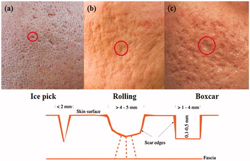
Acne scars can be classified into ice pick, rolling, and boxcar, and each type has its own characteristics.[Citation12] shows an image per type with a diagram of their morphological characteristics. The term ice pick is used because this type of scar is extremely similar to an ice pick mark, as shown in the diagram in . In essence, an ice pick scar has an acute angle; it is small and deep with 2 mm or less in width and 1 mm or more in depth. Because the depth of an ice pick scar is extremely deep in proportion to its width, its bottom is invisible. Ice pick scars appear in the T zone near the nose. A rolling scar is rugged and shallow, and as the diagram in indicates, round and wide. A characteristic of the rolling scar is that it is not distinctive because of its small slope on the border, and its depth is several millimeters. This type of scar appears on the cheeks and near the temples. A boxcar scar is vertical at the border and its bottom is flat. Because the border is distinct, this type of scar is most visible. The shapes of boxcar scars vary with several millimeters in diameter and 2 mm in depth. This type of scar appears on the cheeks and near the temples. The location of a scar is related to the thickness of the skin and the amount of sebum; therefore, the cheeks and temples where the skin is thick tend to have boxcar or rolling scars, whereas the T zone and around the nose where the skin is thin tend to have ice pick scars.[Citation13]
Figure 1. Types of acne scars.
2.2. Tessellation and displacement mapping
Acne is red and convex. However, according to an analysis result on acne scars, some acne scar images indicate that acne scars only have geometric differences with deep furrows where no color change can be identified. That is, the appearance of acne skin is affected by the effect of shades and shadows, both of which are caused by curves. Although acne scars appear along with acne, this study does not consider common acne because acne scars are the concern.
Acne scars are tessellated in the facial part and applied with displacement mapping using a height map. An advantage of tessellation and displacement mapping is the automatic representation of acne scars with such tools during the generation of a height map. A natural representation of acne scars in 3D modeling requires the generation of an appropriate height map. Height mapping is a method that stores digital topographic heights. A height map refers to the structuring of a topological area only with height values, it has a small data size, and the height values can be generated in a black and white image using a graphic tool. The generation of a height map is performed with Adobe Photoshop CS4, where the burn and dodge functions are utilized for a natural expression of skin on the border.
2.3. Result of acne scar simulation
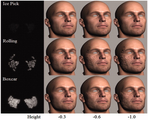
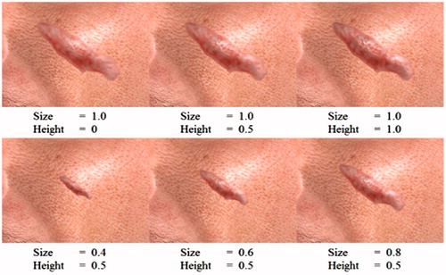
shows the result of appropriate placement of the height map created according to the morphological characteristics of the scars indicated above according to the scar characteristics. The images represent ice pick, rolling and boxcar scars from the top row to the bottom. The ice pick scar image is expressed with narrow and deep scars distributed around the nose. The rolling scar image is expressed with wide, round, and shallow scars around the cheeks and temples. The boxcar scar image is expressed with angular scars around the cheeks. Such acne scars have their own morphological characteristics by scar type, and modeling of such scars in 3D is extremely meaningful because such an attempt has not made presently (to the best of our knowledge), and acne is an extremely common skin condition. Depth control is enabled with the scroll bar in the synthesized system. During the experiment, the height parameters were changed to −0.3, −0.6 and −1.0. Our system provides users with a function for controlling the size and height parameters employed to control the severity of acne scars.
Figure 2. Results of acne scar simulation.
2.4. Scar representation parameter control and automated algorithm for height map generation
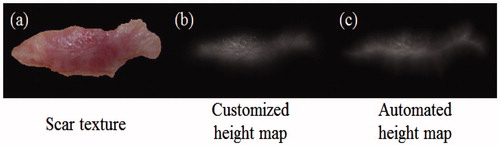
The scar representation technologies used in preceding studies provided no automated scar height control.[Citation8] Our system allows users to automatically generate a height map according to scar characteristics. A height map indicates the difference among scars when the height of a scar is determined. While generating a height map, it should be considered that the height of an actual scar is indifferent from that of the normal skin on the border, and the center of the scar is convex. Therefore, with existing technologies, a scar image is converted to achromatic color with Adobe Photoshop, and then its edge is made blurry, thus allowing a natural connection with the skin on the border. is a scar texture, is an existing customized height map, and is a height map generated with the automated algorithm. For the above, the third image is to be processed, where the distance of each scar pixel to the scar border is calculated, and the color becomes darker as the distance is closer. First, the closest distance to the border d is calculated using n × n mask. Then, the minimum distance is zero and the maximum is n. A weighted value Weight is calculated with EquationEquation (1)(1) .
(1)
Figure 3. Scar height map automation.
According to EquationEquation (1)(1) , Weight is zero when the center of the mask is closer to the scar border, and one when farther. That is, an intended result is earned by directly generating a height map.
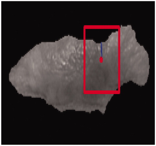
In , we show an example of height map generation with mask size, distance to border and weight. Also, we display some results with size and height parameters that are created by the scar generation algorithm ().
Figure 4. Example of height map generation with automated algorithm.
2.5. Improved subsurface scattering color model
The color calculation model BSSRDF2 (Bidirectional scattering-surface reflectance distribution function) proposed in this study is an improved version of our previous color model, BSSRDF1.[Citation8,Citation9] The color calculation in BSSRDF1 was performed with the ratio of the light attenuation by an optical property parameter to the light intensity. If calculating as a ratio, the thickness is d, and the transmittance of an object is (1 - σad). If the transmitting light is reflected completely, the reflectivity becomes (1 - σad)2. However, the optical properties – absorption and scattering coefficients – determine how much light is absorbed, scattered, and attenuated per unit volume. Hence, it is appropriate for the proposed method, BSSRDF2, to remove the volume of attenuation by the volume of light L, not the ratio; the reflectivity of light not completely transmitted needs to be calculated by (L - 2σad). In consideration of both the reflectivity of the material’s internal scattering in terms of volume and the reflectivity of light reflected on the lower surface during transmission, a new color calculation equation is presented as EquationEquation (2)(2) .
(2)
where σa and σ's are the absorption and reduced scattering coefficients of the wound tissue, respectively. P(g) is the integration of the phase function for backward scatter, and d is the depth. Fdr,t represents the diffuse Fresnel reflectance at the upper boundary. Fdr,b represents the diffuse Fresnel reflectance at the lower boundary.
3. Wound and scar synthesis system
We made a synthesized system in which wounds, bruises, burns, abrasions,[Citation7] scars,[Citation8] and acne scars are combined, and added camera functions – rotation, reduction and enlargement, and move – for views from different angles because results appear as 3D models. Selecting a rendering mode selection for dots, lines, and sides was enabled. To improve a rendering result qualitatively, the proposed system allows the selection of various Shader models. We added a function that shows interaction performance by calculating the frame rate, fps (frame per second) according to the selection mode, and wound and scar insertion. The system offers three skin types. Frequently, wound and scar insertion is a selecting process where the insertion point is selected. However, an acne scar does not require selecting, and a bruise is inputted with a spline value to express a convex. For the above functions, the proposed synthesis system offers intuitive and consistent user interfaces that operate according to the type of wound or scar. Furthermore, it offers a function of modifying some parameters. Various combinations of rendering models can be available depending on specular, diffuse, and ambient light. The number of rendering models in this study is six, and they create appropriate combinations and yield good results.
Figure 5. Result of different size and height parameters with the scar generation algorithm.
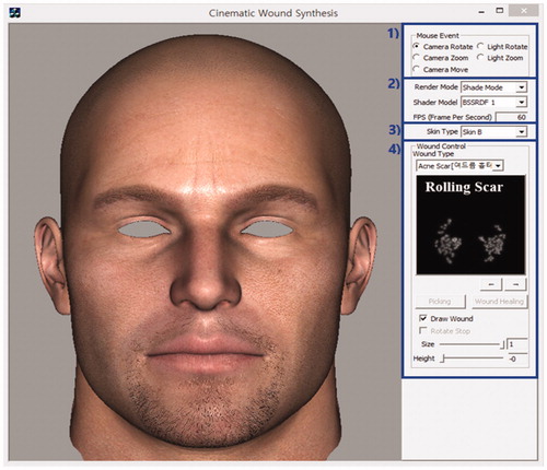
3.1. Interfaces
The user interface of the developed wound and scar synthesis system is presented in . On the left side, the user interface presents a face with inserted wounds and scars. The dialog box on the right shows the options of camera rotation, output method, type and size of wound inserted, and more. The blue outlines on the dialog box indicate the following: 1) controls for the camera and light; 2) controls that render specific settings; 3) selection for skin color type; and 4) controls for the insertion and manipulation of wounds and scars.
Figure 6. Wound and scar synthesis system interface.
3.2. Camera and light control
The interface in which the camera and light are controlled is presented in . Camera and light control can be performed when each function of Mouse Event is selected, and then by moving the mouse while the left button is pressed. When the mouse moves while Camera Rotate or Light Rotate is selected, the y-axis rotates if the mouse moves to the left or right, whereas the x-axis rotates if the mouse moves up and down. Rotation is based on the axes, and what is rotated are the camera and light, whereas the model remains unmoved.
Figure 7. Interface for controlling the camera and light source.
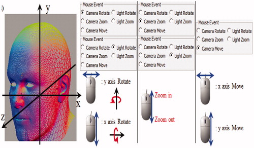
Camera Zoom and Light Zoom are also camera and light moves based on the y-axis. Moving the mouse up zooms in, which is enlargement, whereas moving it down zooms out, which is reduction. Lastly, Camera Move is conceptually the same as moving the origin. When the mouse moves to the right, the facial model moves to the right, and when the mouse moves down, the facial model moves down.
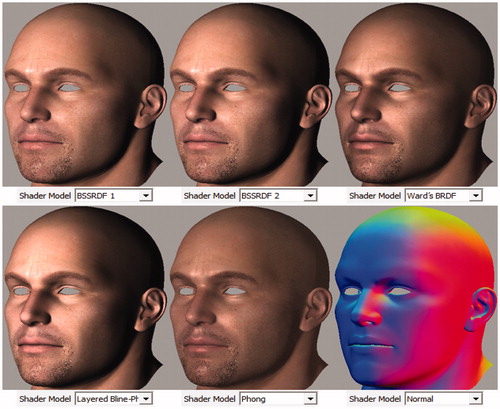
3.3. Rendering and Shader control interface
explains the rendering option setting interface. A Shader model is selected in this interface, and each image represents a rendering result based on BSSRDF1,[Citation8,Citation9] our proposed rendering method BSSRDF2, Ward's BRDF (Bidirectional reflectance distribution function),[Citation14] Layered Blinn-Phong, Phong,[Citation15] and Normal Shader models.
Figure 8. Interface of Shader mode settings.
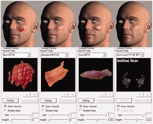
3.4. Wound and scar control interface
The wound and scar insertion and control interface is presented in . A wound, bruise, burn, abrasion, scar, and acne scar can be inserted on the face. Under each face, the result of inserting each type of wound and a different user-control interface per wound type is displayed. In the Wound Type area, when a type to be inserted is selected, the corresponding image for the wound or scar appears below each drop-down list. When the selected wound is inserted, controllable functions per type are provided. Rotate Stop fixes an inserted wound or scar at a given position after a desirable rotation is made. The Size scrollbar controls the size of the inserted wound or scar. A scar and acne scar have a function of height control, which can be performed with the Height scrollbar.
Figure 9. Wound and scar control interface.
4. Assessment methodology and results
4.1. Quantitative assessment
A quantitative assessment is made with fps while running the automated system. Fps is an assessment index used to indicate how smoothly a visual result appears, and how well a user employs the automated system without disconnections. The user can directly view the fps value on the user interface of the synthesis system. Fps is the frequency of outputting to the screen per second. In order to measure fps per type, the system simulates each type to determine the fps.
We conducted an experiment in a computer environment – Windows 8 Pro K, Intel (R) Core (TM) i7-3770 CPU @ 3.40 GHz, NVIDIA GeForce GTX 770**, without Vertical Sync. In the 3D facial model used for the study, the facial part was comprised of 7344 vertices and 14,434 meshes, and the head part was comprised of 3330 vertices and 6336 meshes. indicates the fps per type. When no wound/scar is inserted, fps is 82 on average; approximately 78–79 when a wound is inserted; 60 when a scar with patch generation and tessellation that requires a little bit more running time than without patch and tessellation is inserted; and 69 when an acne scar only with tessellation that does not include a patch on the facial part is inserted. Considering that fps is limited to 60 when Vertical Sync is enabled, the measurement results also show that the system is excellent for use in a real-time game. We found that the comparisons showing there is no big gaps of fps. This means that our method can synthesize any type of wounds, scar and acne scar real-time.
Table 1. fps per type.
4.2. Qualitative assessment
A qualitative assessment is performed through user tests. The qualitative assessment method is a user study in which users simulate each wound/scar on the user interface and assess the results. In addition, the users are assessed on how well they can achieve their purpose using the interface. The questionnaire employed for the assessment includes the items shown in . presents the results of the qualitative assessment with the questionnaire. In the questionnaire, Most Acceptable is assigned five points, Acceptable is assigned four points, Neither Acceptable nor Unacceptable is assigned three points, Unacceptable is assigned two points, and Most Unacceptable is assigned one point. The survey was performed with a total of 50 students who had related majors and experiences with games or computer graphics. Of the participants, there were 21 males and 29 females, and the average age was 21 years. The assessment results on scar simulation were: Wound 4.0, Bruising 4.2, Burn 4.22 and Abrasion 4.38, all of which indicated Acceptable. Scar was given 4.55 and Acne Scar was given 4.6, both of which indicated Most Acceptable. Furthermore, convenience with the interfaces received a 4.43 on average, which is close to Most Acceptable.
Table 2. Qualitative assessment results from a survey.
5. Conclusion and direction of future study
In this study, as the last step of the study on realistic facial modeling where facial wound and scar parameters were reflected, we represented acne scars and synthesized the entire system with an improved subsurface color rendering in addition to what has been developed to date. Tessellation and displacement mapping technologies were used to represent scars using a height map. That which has been developed was synthesized into a system with interface functions in consideration of user convenience. As a result, in the quantitative and qualitative assessments, the user assessment revealed that our system is acceptable. We suggest an applied study in the future that can be used in the medical service field and functional games.
Disclosure statement
The authors declare that there is no conflict of interests regarding the publication of this paper.
Funding
This work was partially supported by NRF grant [No. 2015R1D1A1A01057725] and NRF grant [2010-0008673] and funded by the Government of Korea.
References
- Scheuplein RJ. Handbook of physiology, reactions to environmental agents. Comprehens Physiol. 2011. doi:10.1002/cphy.cp090119.
- Fisher GJ, Kang S, Varani J, et al. Mechanisms of photoaging and chronological skin aging. Arch Dermatol. 2002;138:1462–1470.
- Chisvert A, Sisternes J, Balaguer Á, Salvador A. A gas chromatography–mass spectrometric method to determine skin-whitening agents in cosmetic products. Talanta. 2010;81:530–536.
- Wang C, Wang S, Pan Y, et al. Study on the evaluation of skin moisturizing efficacy of cosmetic. Detergent Cosmetics. 2010;10:32–35.
- Krishnaswamy A, Baranoski GVG. A biophysically-based spectral model of light interaction with human skin. Comput Graph Forum. 2004;23:331–340.
- Weyrich T, Matusik W, Pfister H, et al. Analysis of human faces using a measurement-based skin reflectance model. ACM Trans Graph Proc ACM SIGGRAPH. 2006;25:1013–1024.
- Lee CY, Lee S, Chin S. Multi‐layer structural wound synthesis on 3D face. Comput Animat Virtual Worlds. 2011;22:177–185.
- Choi T, Chin S. Novel real-time facial wound recovery synthesis using subsurface scattering. Sci World J 2014;2014:Article ID 965036.
- Fabbrocini G, Fabbrocini N, Monfrecola A, et al. Acne scarring treatment using skin needling. Clin Exp Dermatol. 2008;34:874–879.
- Goulden V, Stables GI, Cunliffe WJ. Prevalence of facial acne in adults. J Am Acad Dermatol. 1999;41:577–580.
- Rivera AE. Acne scarring: a review and current treatment modalities. J Am Acad Dermatol. 2008;59:659–676.
- Jacob CI, Dover JS, Kaminer MS. Acne scarring: a classification system and review of treatment options. J Am Acad Dermatol. 2001;45:109–117.
- Rao J. Treatment of acne scarring. Facial Plast Surg Clin North Am. 2011;19:275–291.
- Walter B, Notes on the Ward BRDF. Technical Report PCG-05-06 Cornell Program of Computer Graphics; 2005.
- Gotanda Y, Beyond a Simple Physically Based Blinn-Phong Model in Real-Time. SIGGRAPH 2012 course; 2012.