
Abstract
MR-compatibility actuations have been widely investigated for the development of robot-assisted devices under the magnetic resonance imaging (MRI). Ferromagnetic components of MRI-powered can be manipulated remotely using the magnetic force or torque induced by MRI or magnetic field environment. However, (1) numerical analysis of the related factors, geometry and magnitude, influencing the ferromagnetic components, and (2) field non-homogeneities when placed in a uniform main magnetic field B0 are rarely reported. To address the relationship between magnetic force/torque and parameters, different radii of ferromagnetic spheres are required to exert magnetic force and torque with variable magnetic field. Comparison of the field homogeneities error (FHE) under various locations and parameters was investigated. In this study, we present the equivalent model of magnetic field and compare the magnetic force and torque of ferromagnetic sphere under different conditions and provide a safety distance of drive source (ferromagnetic sphere). The numerical models between parameters are established and significant factors were analyzed. Through various parameters of the ferromagnetic sphere, the performance of the numerical model in the magnetic field was evaluated. Cubic polynomial equations were developed to relate magnetic properties of ferromagnetic sphere with R2 > 0.9506. Field homogeneity was not significantly affected when actuation source was installed in 32 cm away from the isocenter.
1. Introduction
Recently, MRI-guided interventional surgery becomes a hot issue in minimally invasive surgery, especially for minimally invasive biopsies and therapies. Compared with the other image modality, such as X-ray, computed tomography (CT), and ultrasonic imaging technology, MRI has excellent soft tissue contrast and the absence of the ionizing radiation for the patients and surgeons.[Citation1] Some groups have developed MRI-compatible needle insertion device to satisfy the MRI environment.[Citation2–6] However, actuation is still crucial challenge for the MRI-compatible device or robot-assist instrument due to the MRI environment. Jake [Citation7] calculated the torque and the force generated by the soft magnetic body; they used a continuous model that unifies two disparate magnetic models. Christian [Citation8] used the MRI scanner to actuate the ferromagnetic objects; this technology is used to demonstrate the feasibility of the magnetic actuation. Pass work on the necessary technologies includes the basic actuation and carrier development.[Citation9] The principle of the approach has been shown in a living swine. Moreover, the recently developed MRI-powered concept offer flexible, interactive multi-axial movement instrument.[Citation10–13] The whole MRI scanner has been used as the energy source that transfers the magnetic energy to the mechanical energy. The principle is based on more small ferromagnetic bodies embedded in the actuator that serves to convert the electromagnetic energy of the MR gradients into mechanical energy. However, these MRI-powered devices always followed ‘design-test’ pattern, not to investigate the actuation compatibility of ferromagnetic materials and relationship between the propulsion force and parameters, which bring about the blindness of the design process.
To our knowledge, no research has been carried out to investigate the effect of force and torque at current range at different volume ferromagnetic body and to establish the relationship between currents, volume, torque and force at given conditions and field non-homogeneities when placed in a uniform main field B0, which is important in the MRI environment. To determine varieties of force and torque based on magnetic actuation before building systems. In this article, we established a finite element method (FEM) model for magnetic torque and force on different volume soft-magnetic materials. By combining separate input currents in each coil to generate magnetic field system that consists of two pairs of combination – Helmholtz and Maxwell coils. The magnetic flux in the region of interest (ROI) can be controlled. The objectives of the present work include: (1) to investigate the effect of force and torque over the current range, (2) to develop models to describe the relationship between the different force and torque at given conditions, and (3) to provide information for developing a force prediction mode in biopsy puncture and installment methods for actuation source.
2. Methods
2.1. Force model on gradient field
In previous literature,[Citation14,Citation15] some groups have discussed the principle of ferromagnetic sphere in gradient field. With my knowledge, when a ferromagnetic materials embedded in a free space that magnetized to convert the magnetic energy into mechanical energy. shows the general view of magnetic materials magnetized in gradient field.
Figure 1. Force model.
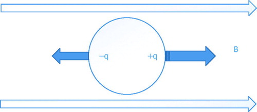
Magnetic material was divided into two poles under the influence of the magnetic field. Force acting on different poles are q/μ0(B0 + dB/2) and q/μ0(B0 - dB/2), respectively,[Citation12] where q is the intensity of the pole and B is the intensity of magnetic field. In addition, the intensity of the pole q is also described as: q = Vμ0σ/dl, where V is the volume of the magnetic materials, μ0 is the vacuum permeability, and σ is the magnetic susceptibility. Thus, the force applied to the ferromagnetic materials is described as:
(1)
2.2. FEM model of conventional gradient field
displays the simplified controlled magnetic field with the combination of Helmholtz and Maxwell coils, which is similar to the literatures.[Citation16] The detail of the controlled magnetic field can be found in . The intensity of the gradient field is controlled by the current intensity through ANSYS package. Ferromagnetic material is placed in the magnetic field, it becomes magnetized rapidly because of the magnetization principle. demonstrates the mesh grid in 3D FE analysis, it is noted that the current 3D FE analysis, the mesh size will influence the results in accuracy and computational cost significantly.
Figure 2. (a) Schematic of magnetic field environment and (b) mesh grid of the region.
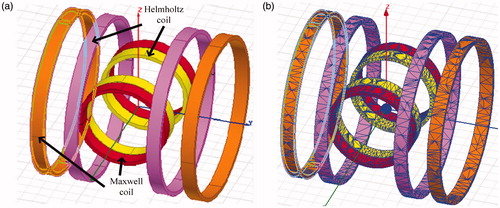
Table 1. Parameters of FEM model and ferromagnetic sphere.
3. Results
3.1. The current-dependent magnetic torque and force
The current-dependent magnetic torque and magnetic force are shown in . It describes the magnetic torque and force of ferromagnetic sphere over the different currents and radii.
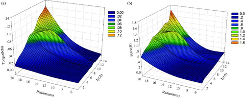
Figure 3. Current-dependent magnetic torque (a) and magnetic force (b) of ferromagnetic sphere at indicated radii.
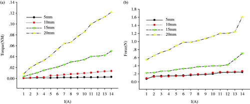
shows the current-dependent magnetic torque and force with different ferromagnetic sphere radius at given conditions. The magnetic torque increased with increasing currents at a given x direction control currents (). For example, when the currents increased from 1 to 14 A of each coil, the magnetic torque increased from 0.003 to 0.05 Nm at 15 mm radius. At 5–10 mm radius, the magnetic torque showed a small increase when the currents increased from 1 to 4 A and then increased to 0.01 Nm when the current increased to 14 A. The magnetic force at 20 mm increased as current increased over investigated range from 0.5 to 1.7 N when the currents increased of each coil (see ). Generally, the magnetic torque on ferromagnetic sphere material increased with the increase of current in the modeled magnetic environment. The same change trends of torque with currents were also found at other x direction control currents.
The simulation results show that uniform magnetic field, magnetic field gradient and magnetic torques, forces are generated in the controlled space. Thus, it was confirmed that ferromagnetic sphere can be aligned and moved in the direction by the present environment field.
3.2. The radius-dependent magnetic torque and force
shows the radii-dependent magnetic torque and force at different coil currents. Both magnetic torque and force increased with increasing radius at given conditions. The magnetic torque and force with the above radius range were also observed at other investigated currents. For example, when the radius increased from 5 to 20 mm, if radius were too large, it would took up more control space and lead to difficult processing process, the magnetic torque increased from 0.002 to 0.12 Nm at 14 A controlled coil currents (see ) and the magnetic force increased from 0.07 to 1.2 N at investigated radius range (see ). When the radius ≤ 12 mm, the magnetic torque showed a small steady trend and then gradually increased, it has a significant guidance on selection of ferromagnetic sphere materials.
Figure 4. Radii dependence of magnetic torque (a) and magnetic force (b) of ferromagnetic sphere (Iy = 7 A).
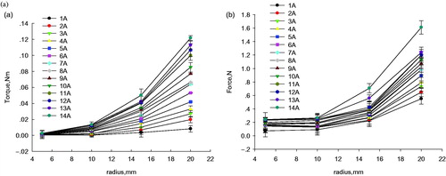
At given currents, the relationship between the increased magnetic torque and force with an increase of radius could be described by quadratic equations, respectively.
(2)
(3)
where y1 and y2 are obtained magnetic torque and force at different radiuses, respectively. a1, a2, b1 and b2 are regression constants.
3.3. Current and radius-dependent magnetic torque and force
shows the magnetic torque and force as a function of y-direction current and radius. The magnetic torque increased with radius and currents, while the controlled currents were equaled to the y-direction currents, and the magnetic torque increased steadily. The polynomial regression models describing the relationship between radius, current, torque and force are listed in EquationEquations (4)(4) and Equation(5)
(5) . Cubic polynomial relationships were fit to correlate the magnetic torque, force with radius and current.
(4)
(5)
Figure 5. Comprehensive influence of radius and Iy currents on magnetic torque (a) and magnetic force (b) with ferromagnetic sphere at Ix = 7 A.
Analysis of variance was carried out to determine whether radius and current had significant influence on the models listed in . The linear, quadratic, and interaction terms of radius and current had strong influence on these models at a 0.0001 significant level (p < .0001). The significant probability of each model was less than .0001 and R2 was .95. It indicates that these models can be used to confirm precisely from known radius and current at selected x-direction current.
Table 2. Significance analysis for ferromagnetic at given conditions.
3.4. Field homogeneities analysis
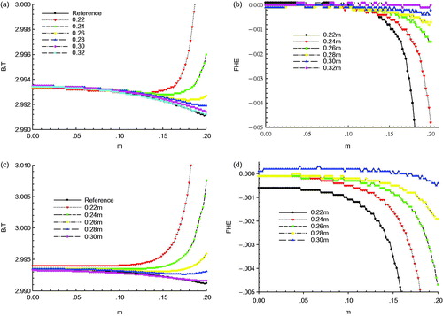
shows field intensity and average FHEs in the FEM environment field intensity and average FHEs in the FEM environment for the different materials' parameters. The vertical axis is the overall average FHEs considering the distances from the center of isocenter. The horizontal axis is the ROI in this case. The results demonstrate field intensity keep the constant trend absence of the ferromagnetic materials. Ferromagnetic sphere (actuation source) cause significant field non-homogeneities when placed in a uniform main magnetic field. The ferromagnetic sphere move to 32 cm, the field intensity for ROI is similar to the reference line (absence of sphere). also indicates the average FHEs for different radii (4 mm (b), 6 mm (d)), respectability, it is important for MRI requirement.
Figure 6. Average field intensity (a), (c) and FHEs (b), (d) in the ROI at different distances.
4. Discussion
In order to verify the reliability of the models, predict the magnetic force and torque of the ferromagnetic sphere under the condition of currents and radiuses, comparison between calculated contents and actual ones is provided in . The vertical axis is the different calculated values using the numerical model; the horizontal axis is the different actual values. Different colors show the errors between actual ones and predicated ones. If the magnetic torque and force of ferromagnetic sphere could be obtained at a constant current, the radius of ferromagnetic sphere can be calculated by equation. expresses the points of calculated contents against the actual ones evenly and closely distributed on both sides of the lines at 45°, indicating that the predicted contents were close to the actual ones from EquationEquations (4)(4) and Equation(5)
(5) .
Figure 7. Calculated contents obtained using Equation (4) (a) and Equation (5) (b) against the measured ones.
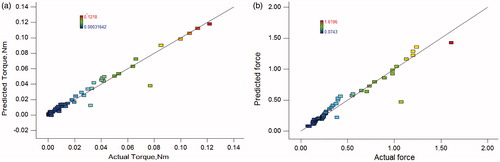
The model evaluation tells that the regressed linear models could be used to determine the magnetic force and torque of ferromagnetic sphere material when the radius and current are known.
In addition, ferromagnetic sphere can cause significant field non-homogeneities due to its susceptibility differences with respect to surrounding area. From the MRI view, this so called field non-homogeneity has a dual effect of local frequency shifts and local gradient perturbations. With the help of results, the source of field non-homogeneity has been used as a form of image contrast for visualization and tracking of the actuation source (ferromagnetic sphere).
From the shown results, the proposed model can use the capabilities of magnetic gradient environment to propel ferromagnetic objects. The geometric parameter of ferromagnetic sphere can lead to significant time savings to speed up the design process. Therefore, the optimization of the parameter of ferromagnetic sphere is necessary during modeling and analysis. The target of the proposed models and analysis is to explore the feasibility creating force and torque with magnet. For MRI-guided surgeries, the MRI scanner itself provides a strong magnetic field. Thus, the final application of this article is to provide actuator for MRI-guided needle biopsy. Further effort has to be spent on optimizing the parameters and achieving higher repetition rates. Higher repetition rates will enable the propulsion. This has to be evaluated and improved. Furthermore, the relationship between magnetic torque or force and radius is applied should be studied to clarify and control the behavior of the robot system.
5. Conclusion
The results show the magnetic force and torque on ferromagnetic sphere increased with the increase of current and radius. Furthermore, in order to confirm the relationship between parameters and force/torque, we presented mathematical model with considering the radius and currents, and make a significant analysis comparison. The results show the detailed information between magnetic field and parameters of ferromagnetic sphere. Consequently, the numerical model was validated. Comparison of different ferromagnetic sphere parameters for filed homogeneity was provided, which helps us to provide some information on the installment of the actuation source.
Disclosure statement
The authors report no conflicts of interest. The authors alone are responsible for the content and writing of this article.
Funding
This work was supported by National Natural Science Foundation of China [Grant No. 51605385] and Fundamental Research Funds for the Central Universities (3102015JCS050-10), Innovation Foundation for Doctor Dissertation of Northwestern Polytechnical University (CX201515) and the State Scholarship Fund of China (No. 201506290164) from Chinese Scholarship Council.
References
- Yu N, Gassert R, Riener R. Mutual interferences and design principles for mechatronic devices in magnetic resonance imaging. Int J Comput Assist Radiol Surg. 2011;6:473–488.
- Srimathveeravalli G, Kim C, Petrisor D, et al. MRI-safe robot for targeted transrectal prostate biopsy: animal experiments. BJU Int. 2014;113:977–985.
- Tokuda J, Song SE, Fischer GS, et al. Preclinical evaluation of an MRI-compatible pneumatic robot for angulated needle placement in transperineal prostate interventions. Int J Comput Assist Radiol Surg. 2012;7:949–957.
- Wang WD, Zhang P, Shi YK, et al. Design and compatibility evaluation of magnetic resonance imaging-guided needle insertion system. J Med Imag Health Inf. 2015;5:1963–1967.
- Wang WD, Shi YK, Goldenberg AA, et al. Experimental analysis of robot-assisted needle insertion into porcine liver. Biomed Mater Eng. 2015;26:S375–S380.
- Wang WD, Shi YK, Yang N, Yuan XQ. Experimental analysis of drilling process in cortical bone. Med Eng Phys. 2014;36:261–266.
- Abbott JJ, Ergeneman O, Kummer MP, et al. Modeling magnetic torque and force for controlled manipulation of soft-magnetic bodies. IEEE Trans Robot. 2007;23:1247–1252.
- Dahmen C, Wortmann T, Fatikow S. Actuation and tracking of ferromagnetic objects using MRI. Int J Optomechatronics. 2012;6:321–335.
- Chanu A, Martel S, IEEE. Real-time software platform design for in-vivo navigation of a small ferromagnetic device in a swine carotid artery using a magnetic resonance imaging system. Paper presented at: 2007 Annual International Conference of the IEEE Engineering in Medicine and Biology Society, Vols. 1–16. Proceedings of Annual International Conference of the IEEE Engineering in Medicine and Biology Society. New York: IEEE; 2007. p. 6585–6588.
- Bergeles C, Vartholomeos P, Qin L, Dupont PE, IEEE. Closed-loop commutation control of an MRI-powered robot actuator. Paper presented at: 2013 IEEE International Conference on Robotics and Automation ICRA. New York: IEEE; 2013. p. 698–703.
- Vartholomeos P, Bergeles C, Qin L, Dupont PE. An MRI-powered and controlled actuator technology for tetherless robotic interventions. Int J Robot Res. 2013;32:1536–1552.
- Ouchi R, Saotome K, Matsushita A, Suzuki K. Development of an MRI-powered robotic system for cryoablation. Conf Proc IEEE Eng Med Biol Soc. 2015;2015:1186–1189.
- Bergeles C, Qin L, Vartholomeos P, Dupont PE. Tracking and position control of an MRI-powered needle-insertion robot. Conf Proc IEEE Eng Med Biol Soc. 2012;2012:928–931.
- Eqtami A, Felfoul O, Dupont PE, IEEE. MRI-powered closed-loop control for multiple magnetic capsules. Paper presented at: 2014 IEEE/RSJ International Conference on Intelligent Robots and Systems. New York: IEEE; 2014. p. 3536–3542.
- Pawashe C, Floyd S, Sitti M. Modeling and experimental characterization of an untethered magnetic micro-robot. Int J Robot Res. 2009;28:1077–1094.
- Cao QL, Han XT, Zhang B, Li L. Analysis and optimal design of magnetic navigation system using Helmholtz and Maxwell coils. IEEE Trans Appl Superconductivity. 2012;22:4401504.