
Abstract
A novel separate robotic system for minimally invasive surgery (MIS) has been presented in this paper. Control system architectures were designed, basing on versatile performance criteria. The compact control and mechanical structure were suitable for medical environment. Function and safety design satisfying medical application were integrated into the robot system as well. Additionally, intuitive control algorithm solved the problems of hand-eye incoordination and workspace mismatch between master hands and slave arms during the master–slave control process. A series of experiments have been accomplished to evaluate the performance of the robotic system at last. The results demonstrated that the robotic system was capable of executing surgical operation intuitively and implementing auxiliary functions perfectly, which meant that the control system was feasible and reliable.
1. Introduction
Minimally invasive surgery (MIS) has been adopted by more and more patients, because the minimally invasive technique allows surgeons to insert thin instruments and an endoscope into patient’s abdomen cavity through only three small incisions.[Citation1,Citation2] Patients can have less pain, smaller trauma, and recover more quickly after the MIS, in contrast with the effect of the traditional open surgery.
However, robotics also makes the MIS technique carry forward. The minimally invasive surgical robot can not only assist surgeons to execute intuitive surgical operation, but also liberate surgeons from the heavy labor intensity of the surgery and contribute to cut the learning curve down for the MIS technique. Therefore, many robot-assisted systems for MIS are developed as experimental or commercial subject all over the world.
The Da Vinci robotic system, manufactured by Intuitive Surgical Company, is the most successful commercial surgical robot when it comes to robot-assisted surgery technique.[Citation3–6] It has been approved by FDA of United States of America and been applied to the clinic in many medical institutions. The kernel computer takes charge of transforming the motion information of surgeon’s hands to the movement commands, which are transmitted to digital signal processor (DSP) to actuate joint motors for robotic joints’ motion. In Poland, researchers developed a series of surgical robots called ‘Robin Heart’.[Citation7,Citation8] The Robin Heart robots also use kernel computer and DSP as main control units. Meanwhile, data exchange can be realized by Controller Area Network (CAN) protocol. For now, the researchers are preparing for the clinical tests after series of animal and teleoperation experiments. The Telelap ALF-X MIS robot is another listed surgical robot, which is designed by SOFAR S.P.A. It is the novel eye tracking and tactile feedback system that distinguish the ALF-X from other surgical robots.[Citation9–12] This robot has been successfully applied to the clinic. The University of Washington developed RAVEN surgical robot with Phantom Omni haptic devices as master manipulators and four slave manipulators beside the sick bed.[Citation13–16] The kernel computer controls the slave manipulators based on TCP/UDP transport protocol. But, the slave joints do not have encoders which increases the uncertainty in griper pose. It has entered to the phase of animal tests.
In this paper, we develop a new robot-assisted system for MIS, and present the multilevel control system in detail. First, the overview of the new surgical robot system is proposed in Section 2. Second, Section 3 presents the design of control system including hardware system design and software architecture. In Section 3, function and safety design principles are established for its versatility. Meanwhile, intuitive control method is proposed to realize hand-eye coordination. Moreover, the validity of the presented control system is proved by some experiments in Section 4. At last, we make summarization of our research and propose the future work in Section 6.
2. Overview of the novel minimally invasive surgical robot
A new robotic system for MIS with three separate slave robotic arms has been designed by us. The whole system is supposed to consist of one console and three separate slave robotic arms, which include two slave robotic arms with surgical instruments, and one with a laparoscope as presented in . The three separate slave robotic arms share the same mechanical and control structure.
Figure 1. Robotic system minimally invasive surgery. (a) Console (b) Slave arm.
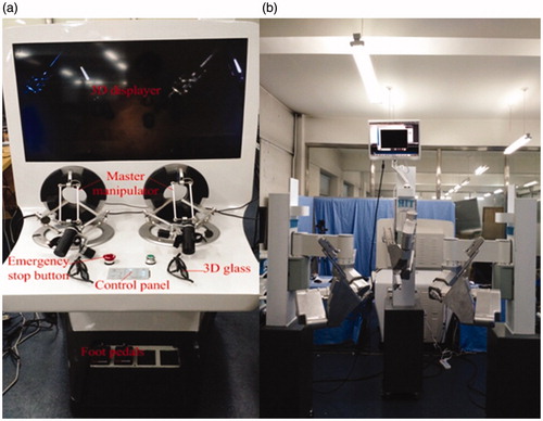
Actually, the surgeon is allowed to control the slave robotic arms at the control console in . It includes a control panel, foot pedals, 3D displayer, emergency stop button, and two master manipulators. System parameters setting and adjustment function are realized by control panel and foot pedals before or during the surgery. Omega 7 haptic devices with seven degrees of freedom (DOF), manufactured by Force Dimension Company, are selected as master hands. They are capable of capturing and transforming the motion information of surgeon’s hands to position and orientation signals. Specifically, the first three joints constitute a parallel mechanism together so that they can be used as positioning mechanism. The other three joints, axes of which intersect at a common point, compose series mechanism for outputting gesture information. The last DOF is designed for grasping. They also provide force feedback, which is still reserved since there is no haptic information fed back from the slave arms at current phase. The 3D glasses can help surgeon to observe the surgical instruments and surgery scene on the 3D displayer.
As shown in , each slave mechanical arm connects a movable cart and altogether owns six DOFs. Joint1, joint2, and joint3 are the passive components. They are allowed to manually move before operation to locate the remote center point coinciding with the incision. Once the locating work is completed, the passive components are locked by a button controlling electromagnetic clutches. There are no motors, just absolute encoders at each passive joint for feeding the position information back.
Figure 2. Slave mechanical arm and instrument.
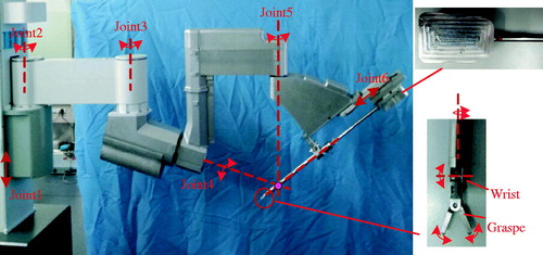
In addition, the active components together, from joint4 to joint6, constitute the remote center motion (RCM) mechanism. A triangle mechanism is developed as the RCM mechanism in this paper. This mechanism belongs to the series mechanism, each joint axis of which intersects at one point called remote center point. The instrument is able to be inserted into the abdomen through the remote center point. Meanwhile, defining the incision in patient’s abdomen cavity as the remote center point makes it possible that movements of the instrument do no harm to the incision anytime. Each active joint can be driven by a servo DC motor and manual operation. Position information is also acquired through absolute encoders. A surgical instrument or laparoscope is installed on the prismatic joint6 platform. Joint servo DC motors are utilized to actuate steel wires to realize motions of the end effector of the instrument in four directions of DOFs. The wires driving graspers are arranged to go across the holes punching in the wrist wire wheel, which avoids producing coupled motion between graspers and the wrist. Therefore, the surgeon is more capable of surgical operation, such as a suture, without coupling. As for the laparoscope, there are no motions after being assemble into the joint6 platform.
3. Control system design
During the design processes of control system, it is one imperative design criterion that the MIS robot is guaranteed to become a versatile robotic system. It is designed to satisfy not only surgical require and environment, but also excellent extensibility and safety. A series of design criteria have been proposed and implemented for the robot as follows:
Safety: the kernel principle, considered in the whole design period; portability and compact structure for easily integrating into the operating room; friendly and intuitive human-interactive design to facilitate the surgeon to grasp the technique of operating the robot within the minimal amount of time; joint motion components, such as motors, drivers, and electrical connection integrated into the slave robotic arms for compact dimensions and electrical safety; open design concept for extending system with the development of medical demand.
3.1. Hardware system design
The surgical robot proposed in this paper belongs to the master–slave robot. It includes a console where a surgeon controls the slave robotic arms and three separate slave robotic arms beside the patient, as presented in . For the console, it is capable of realizing a majority of control functions on the system, such as system running control, slave robot adjustment, manual intervention, and so on. Two mentioned Omega 7 master manipulators have been set up to control the three slave arms. A control panel and foot pedals are utilized to configure parameters, adjust slave arms, and execute auxiliary operation. A 3D displayer is equipped in order to show the 3D real-time images in patient’s abdomen transmitted through the laparoscope, which forms control closed loop with surgeon’s hands. Each module connects to the kernel controller, industrial personal computer (IPC), by standard interfaces. As for the communication level, scalable Ethernet transmission mode is adopted between the console and slave robot.
Figure 3. Hardware architecture of MIS robot system.
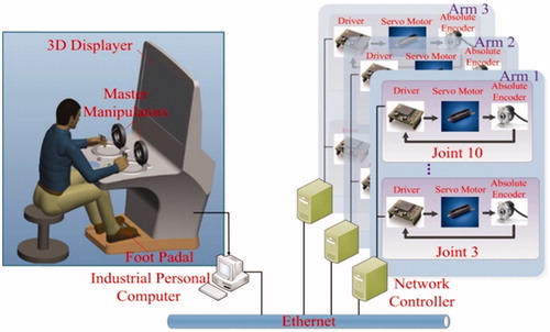
In each slave mechanical arm, the network controller is responsible for receiving commands from the console and communicating with drive units through EtherCAT field bus to actuate active joints and instrument. Absolute encoders are also installed in joints as redundant position sensors. All the drive units, sensors, and motors are integrated inside the robot arm.
3.1.1. Functional design
It is better to provide distinct refined ability for different surgical operation in a robot-assisted MIS, which is absent in traditional artificial MIS. To achieve that meticulous operation, an operating accuracy selection function is designed on the control panel. Generally, surgeon is allowed to set appropriate master–slave control scale to shrink the motion of surgeon’s hands followed by slave arms.
In addition, an adjusting function for master manipulators can be carried out by stepping on the foot pedal. The adjusting function is applied once master hands arrive at their extreme positions of their reachable workspace, yet the instrument is not at the target position. The slave arms keep stationary, and mater hands are adjusted to a suitable position as the foot pedal is closed. After the adjustment, the instruments continue to follow master hands to move from wherever they stop.
Backdriving control function has been utilized on slave robot arms. This function helps surgeon to drive robot in manual mode. The position of the instrument tips can be configured at any place in the workspace by backdriving control.
3.1.2. Safety design
In view of the application scope of the robotic system, safety design should be the most considered problems. Limit switches and potentiometers are respectively installed on the active joints and instrument joints to protect joints from exceeding the position limits. For electronic design, Electro Magnetic Compatibility (EMC), wiring effort, and signal noise are the foremost safety issues. These influences can be reduced by compactly integrating the electronic modules inside the robot arm made of metal material and routing nearby the physical interface. Meanwhile, highly modular design and standard interfaces are applied for favourable compatibility and expansibility. Furthermore, drive units are capable of monitoring the status of motors and preventing them from running errors. Emergency stop switches are also set up on both sides of console and slave arms.
3.2. Software system design
Basing on the master–slave control architecture, the control software is designed to be divided into main control part and network control part. In , the main control program is developed in the IPC, which is responsible for running the entire robotic system. It monitors and receives the signals come from the control panel and foot pedals for auxiliary operation and configuring system arguments prior to running the system. In this part, the position and orientation information of surgeon’s hands gained from master manipulators is utilized to calculate the motion information of slave robot arms in joint space, which is sent to the network controller to drive joints.
Figure 4. Software architecture of MIS robot system.
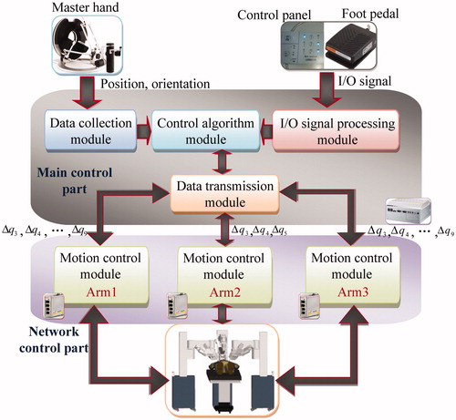
In the main control part, an intuitive control method is applied as the control algorithm module. In robot-assisted MIS, the surgeon sitting front the console performs surgical operation under the guide of the 3D displayer showing the real-time images of the surgery scene. It is indispensable to keep the motion of the master manipulators consistent with the motion of slave instruments in the 3D displayer. To solve the master–slave consistency problem, we present an intuitive control strategy. It needs to transform the position and orientation of the master manipulator relative to the 3D displayer into the position and orientation of the slave instruments relative to the laparoscope. EquationEquation (1)(1) shows the relationship between the master side and slave side:
(1)
where, S1I T is the position and orientation matrix of surgical instrument end relative to the base coordinate system of the slave arm, S1LA represents the transformation matrix from the base coordinate system of instrument-holding arm to the end of the laparoscope, MHT is the position and orientation matrix of the end of the master hand relative to its base coordination system, DMA denotes the transformation matrix from the base coordinate system of the master manipulator to the 3D displayer.
Simultaneously, an increment control algorithm is used because the Omega 7 master manipulator have different mechanical configuration from the slave manipulator and their workspaces are also not match as well. However, it is remarkable that the increment control is only employed in master–slave position control. Thus, (1) can be rewritten as:
(2)
(3)
In (2) and (3), HMR and S1IR are respectively the orientation matrix of the end point of mater hand and instrument. ΔHMP and ΔIS1P respectively express the position offset of the end point of mater hand and instrument. The scale factor for different operation accuracy is written as k.
The network control part is programmed in the network controller. It aims at transmitting the joint motion information to drivers and feeding joint position back to IPC. For the safety of the robotic system, the program can also monitor the condition of motors, and take action according to different status of motors.
4. Experiments
To verify the performance of control system of the novel MIS robotic system, some experiments have been designed and executed by using the existing conditions.
4.1. Master–slave trajectories following experiment
It is core function for the MIS robotic system that the ends of instruments must be capable of reaching specified space positions and following the movements of surgeon’s hands well. The performance of master–slave trajectory following has been confirmed by means of the master–slave motion experiment on the training module in .
Figure 5. MIS training module.
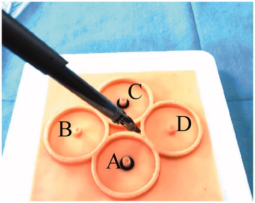
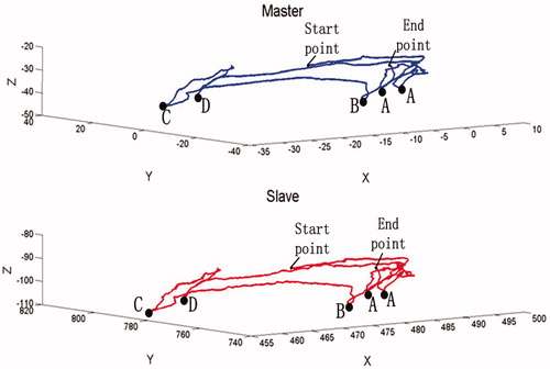
In this test, the operator manipulated one master hand to control the instrument at the slave side to reach the columns, A, B, C, D, of the training module. Simultaneously, the space position coordinates of the end of the master manipulator and instrument, for forming motion trajectories, were recorded by being acquired directly from the master hand and forward kinematics according to the slave joints position feedback from absolute encoders. As shown in , the instrument manipulated by the master hand successively touched the columns of the training module in order of A, B, C, D, A. Thus, the above blue line was the motion trajectory drawn by space position coordinates of the master manipulator, and the red line denoted the trajectory of the end of instrument generated when it followed the motion of the master hand. The space position coordinates of two points A did not coincide because it was impossible for the operator to arrive at the identical space coordinate by eyes and hands. In spite of this, it can be seen from that the slave instrument was able to arrive at the specified space positions, and the motion trajectories were quite coincident for the master hand and instrument. The results showed the instrument could reproduce the motion of the master manipulator very well in its own workspace, which means the robotic system possesses excellent tracking performance. It also confirmed the availability of the control algorithm.
Figure 6. The motion trajectories of the end of master hand and instrument.
4.2. Suturing and knotting experiments
Suturing and knotting were the important parts in the surgery. For detecting the performances of control system, suturing and knotting on training module were appropriate experiments to be carried out in this paper. The operator utilized 3D images of the simulative surgical scene obtained from the 3D visual feedback device and master–slave control to complete the surgical operation. The process is demonstrated in and .
Figure 7. Suturing experiment on the training module.
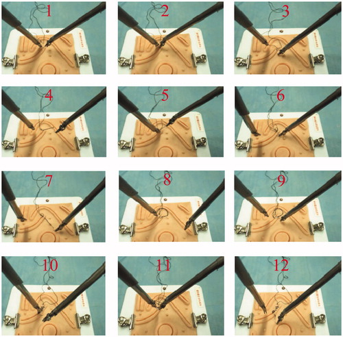
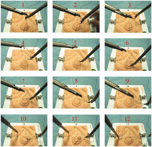
Figure 8. Knotting experiment on the training module.
Two needle holders as instruments were assembled in two slave arms for both experiments. In suturing process from step 1 to 4, one instrument clamped the suture needle, pierced one side of the incision from outside to inside and went through the tissue on the same side. Next, the needle was released and pulled out of the tissue by the other needle holder. Then, the needle was delivered to the first instrument to complete the same operation on opposite side but from inside to outside of the incision described from step 5 to 7. Afterward, operator adjusted the position and gesture of the instrument and repeated the operation to form a suture ring on the surface of the incision as shown from 8 to 12.
Knotting was the subsequent step after suturing operation. This operation needed one instrument to cooperate with the other instrument. In steps 1, 2, 3, 4, and 5 of , the first needle holder clamped one end of the suture and the second needle holder rotated around the suture to make it a circle with assistance from the first instrument. Then in the following remaining steps, the first instrument loosened the suture to make sure that the second needle holder is able to pass through the circle, clamping the other end of the suture. After that, a knot was not created until the other end of the suture had been pulled out of the circle completely. Eventually, two instruments moved in two opposite direction for tightening the knot. Usually, the second knot with opposite knotting direction was made by repeating the above steps.
The results of suturing and knotting were also revealed in and . The surgical robot was capable of effectively accomplishing suturing operation and tying a knot under the cooperation of two slave robotic arms. The success of suturing and knotting proved the surgical robot had not only sufficient flexibility but also adequate force for suturing and knotting in the experiments. The results indicated the whole control system, including accuracy selection, master hand adjusting functions, and intuitive control algorithm, and so on employed in the tests, was effective and reliable too.
5. Discussion
The surgical robotic system is a versatile system designed by a series of design criteria which are formulated according to demands of the surgical environment for robot. In the aspect of mechanical structure, compact series mechanism is adopted for larger workspace, and three independent robotic arms with movable carts increase the portability of robots. Moreover, each independent robot can be used as an individual surgical robot, such as a laparoscope robotic arm holder. The triangle mechanism is designed for no injuries happening to the incision on patient’s body no matter how the instrument moves. The slave robotic arm contains passive and active joints which can be adjusted to the appropriate position on the basis of various surgical requirements.
According to the open design criterion, the whole control system owns good expandability for the development of medical demand. Comparing with traditional MIS, surgeon can complete surgical operation in the case of hand-eye coordination because of the intuitive control method. Furthermore, the operator’s hands are always in comfortable zones of the master manipulators owing to the adjusting function and increment control algorithm.
During the robotic system, safety is the kernel principle which is considered in the whole design period. Metal robotic arms, electronic modules compactly integrated inside the robot arm, and routing nearby the physical interface improve the electric safety as well as limit protection in hardware and software, emergency stop switches, status monitoring, etc. Ultimately, the successful experiments prove that all the efforts are worth it.
6. Conclusion
The control system of a novel separate robot for MIS is presented in this paper, including hardware system and software system. The robotic system owns a console and three separate slave robot arms. A surgeon at the console controls slave robot arms with the help of two master manipulators and a 3D displayer, which provides the surgeon with the images of the surgery scene in patient’s abdomen transmitted from the laparoscope in the slave robot. The control system design is based on the versatility principle. The Ethernet communication between the console and slave robot and the EtherCAT field bus can afford the good expansibility to the robotic system. Functional design enhances the ease of use of the robotic system. Moreover, safety design as the crucial design criterion is integrated into the robotic system for its medical application. Softwares in the IPC and network controller are responsible for the robotic system running together. The intuitive control method is adopted to make surgeon’s eyes and hands coordinated regardless of the distinctions of the mechanism structure and workspace between the master hands and slave robotic arms. Eventually, a series of experiments have been designed and executed in the master–slave control mode. The results of experiments show that the robotic system integrating functional design and intuitive control strategy is capable of accomplishing complex surgery operation and the control system is also stable and effective for a MIS.
For the future work, some animal experiments have been put on the agenda. We will find out and handle the problems discovered in the animal experiments. After that, the motion paths of the slave arms are needed to be optimized and smoothed to promote the performance of the robotic system. The accuracy is also expected to be improved by error compensation method.
Disclosure statement
The authors report no conflicts of interest. The authors alone are responsible for the content and writing of this article.
Funding
This work was supported by the National High Technology Research and Development Program of China (‘863 Program’) [grant No. 2012AA041601], the National Natural Science Foundation of China [grant No. 61305139], Self-Planned Task [grant No. SKLRS201406B] of State Key Laboratory of Robotics and System (HIT), the Fundamental Research Funds for the Central Universities [grant No. HIT. NSRIF. 2013052].
References
- Hulka JF, Reich H. Textbook of laparoscopy. Philadelphia (PA): W.B. Saunders; 1994.
- Hunter JG, Sackier JM. Minimally invasive surgery. New York: McGraw-Hill; 1993.
- Shio M, Madoka S, Shigeru W, et al. Development of minimally invasive surgery systems. Hitachi Rev. 2003;52:189–195.
- Guthart GS, Salisbury JK, The intuitive telesurgery system: overview and application. Proceedings of 2000 IEEE/ICRA; 628–621; San Francisco, CA; 2000.
- IntuitiveSurgical.com [Internet]. Sunnyvale (CA): Intuitive Surgical Inc. [cited 2016 Feb 28]. Available from: http://www.intuitivesurgical.com/.
- Satava RM. Surgical robotics: the early chronicles – a personal historical perspective. Surg Laparosc Endosc Percercutan Tech. 2002;12:6–16.
- Nawrat Z, Kostka P. Robin heart surgery robotic system: challenges in mechanical construction, control system and stuff training before first clinical application. Arch Mech Eng. 2014;61:163–178.
- Niewola A, Podsedkowski L, Wroblewski P, et al. Selected aspects of robin heart robot control. Arch Mech Eng. 2013;LX:575–593.
- Beasley RA. Medical robots: current systems and research directions. J Robot. 2012;2012:1–14.
- Stark M, Gidaro S, Morales ER. The future of gynaecological surgery-telesurgery with haptic sensation. Gineco Ro. 2011;7:210–213.
- Larocca V, Marino F, Filippis A, et al. A new operative telesurgical system: Telelap Alf-X experiment study on animal modal. J Adv Biotechnol Bioeng. 2014;2:12–15.
- Anvari M. Robotics in general surgery. Part XV: the future of robotic platforms. New York: Springer; 2014; p. 485–497.
- Blake H, Rosen J, Glozman D, et al. Raven-II: an open platform for surgical robotics research. IEEE Trans Bio-Med Eng. 2013;60:954–959.
- Li Z, Glozma D, Milutinovic D, Maximizing dexterous workspace and optimal port placement of a multi-arm surgical robot. 2011 IEEE International Conference on Robotics and Automation; 3394–3399; Shanghai, China; 2011.
- Lewis A. Dynamically evaluated gravity compensation for the RAVEN surgical robot [dissertation]. Washington (DC): University of Washington; 2013.
- Velasquez CA, King HH, Hannaford B, et al. Development of a flexible imaging probe integrated to a surgical tele-robot system: preliminary remote control test and probe design. The Fourth IEEE RAS/EMBS International Conference on Biomedical Robotics and Biomechatronics; 894–898; Rome, Italy; 2012.