
Abstract
Purpose: The in situ fenestration of a standard endograft is currently limited by difficulties in targeting the fenestration site under fluoroscopic control and by the lack of a safe method to perforate the graft. Evidence in the literature suggests the use of a 3 D electromagnetic navigator to accurately guide the endovascular instruments to the target and a laser to selectively perforate the graft. The aim of this work is to provide design guidelines to develop a sensorized catheter to guide the laser tool to the fenestration site and conduct preliminary testing of the feasibility of the proposed solution.
Matherials and methods: Different catheter designs were delineated starting from engineering considerations, then prototypes were preliminarily tested to collect surgeon opinions and to steer the design process toward the preferred solution reported by the user. Finally, mechanical simulations were performed with CathCAD, a design software system for the development of composite tubing for endovascular catheters.
Results: Based on surgeon feedback, a 9-French steerable catheter with a stabilization system was designed. CathCAD simulations allowed us to define the construction parameters (e.g., materials and geometric constrains) for the fabrication of composite tubes with mechanical properties (flexural, axial, and torsional rigidities) compatible with target values in the literature for guiding catheters.
Conclusion: The presented results preliminarily demonstrate the clinical reasonability and feasibility of the designed tool in terms of mechanical properties. Further mechanical tests and extensive in vitro clinical trials are required prior to animal testing.
1. Introduction
Endovascular aortic aneurysm repair (EVAR) is a catheter-based surgical technique that allows for minimally invasive repair of aortic aneurysms with the implantation of a stent graft within the aneurysmal sac. Fluoroscopy, a two-dimensional imaging modality based on X-ray radiation, is used to support navigation of endovascular instruments through blood vessels.
Maintaining adequate perfusion of collateral vessels that originate from the aorta is a key aspect in the treatment of aortic aneurysms. In case of juxtarenal infrarenal aneurysms (‘aneurysms that involve the infrarenal abdominal aorta adjacent to or including the lower margin of renal artery origins’ [Citation1]), traditional stent grafting can occlude the aortic branches and block blood flow to vital organs.
For this reason, patient-specific fenestrated stent grafts with customized holes to preserve flow to essential collateral arteries have been developed [Citation2–4]. Fenestrated grafting, however, is technically challenging and time-consuming since stent graft fenestrations should be aligned with the target collateral vessels. This procedure requires a great deal of technical skill and precision. In addition, several changes and re-adjustments of the C-Arm position/orientation are necessary to determine the best viewing direction, which results in prolonged fluoroscopic exposure times. Customized grafts are also expensive and not available for acute syndromes, since fabrication requires several days. Therefore, alternatives, such as the in situ fenestration of a standard stent graft, have been proposed [Citation5]. However, the reliability of this procedure, especially for abdominal aneurysms, is limited by the lack of a safe method to perforate the graft and by the difficulties in identifying the target fenestration site because after endograft deployment, the contrast medium flow is blocked by the endograft wall, thus inhibiting visualization of the collateral arteries by angiography.
In regard to the first issue, recent studies have proposed the use of laser systems to selectively and rapidly perforate the graft material preventing injuries to the arterial wall [Citation6–9]. Concerning the second issue, our research group and others [Citation10–13] have demonstrated that a three-dimensional (3 D) computer-aided guidance system, based on the electromagnetic (EM) tracking of the surgical tools, can be a reliable solution to guide the endovascular instruments to the target site. These systems can use intraoperative data, such as 3 D ultrasound or 3 D rotational angiography, as a source to extract the 3 D model of the patient anatomy or important information for guidance of the endovascular instruments, such as vessel lumen centerline [Citation14–16].
The idea behind this work is that the integration of a laser system into a 3 D EM navigation platform can potentially overcome the limitations of the present in situ fenestration technique, providing the surgeon with a selective fenestration tool whose position and orientation can be accurately tracked in real time within a 3 D virtual model of the patient vasculature.
More specifically, the idea is to use a guidewire tipped laser fiber (a laser fiber incorporated into a guidewire) to deliver the laser energy to the graft material at the target fenestration site. The efficacy of such a fenestration system is heavily dependent on the navigator accuracy, proper setting of the laser, and proper design of the device used as a guiding catheter for the laser tool.
This work focuses on this latter aspect, and it aims to provide a sensorized guiding catheter for the navigation and positioning of a guidewire tipped laser fiber at the fenestration site. First, the main requirements of this catheter are discussed and different design strategies to accomplish the desired specifications are described. Finally, the results of preliminary tests performed to define the optimal solution from a clinical point of view are presented and the mechanical feasibility of the selected design is verified.
2. Materials and methods
A guiding catheter is an endovascular device used to facilitate passage of a smaller catheter or another endovascular instrument through a tortuous region to the intended target area within the vessel [Citation17]. As a specific application, the guiding catheter will be used to navigate a fenestration tool, i.e., a laser fiber incorporated into a 0.035’’ nitinol tube.
First and foremost, this guiding catheter should reach the designated fenestration site without causing injury to the arterial wall. More specifically, it should be easily advanced through the femoral arteries into the abdominal aorta to reach the appropriate longitudinal position along the main axis of the aorta/prosthesis and then easily rotated to correctly orient the laser fiber tip toward the fenestration site.
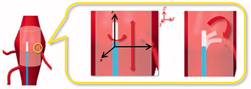
For optimal fenestration of the endoprosthesis, the laser fiber tip, and thus the catheter tip, should be positioned perpendicular to the graft surface [Citation18]. This requires proper bending of the catheter tip. Finally, once the proper longitudinal and rotational alignments are reached, the mechanical support and stability of the catheter must be maintained during fenestration ().
Figure 1. Targeting of the stent graft fenestration site (highlighted with a yellow circle) during an EVAR procedure. Two coordinate systems are represented: a global system (XYZ) in red and a local system (xyz) related to the guiding catheter body in black. Precise targeting requires proper catheter positioning along the longitudinal direction (Z axis), rotation around the catheter main axis (z axis), and bending of the catheter tip (in the yz plane).
To meet these requirements, the catheter should be designed to provide a proper pushability (the ability to transmit the force along the catheter main axis and to push the catheter through the vascular system and the stenoses to reach its final destination), torqueability (the ability to rotate the catheter tip by turning its proximal portion), and flexibility (the ability of the catheter to conform to the vascular anatomy, reducing the force applied to the tissue). These properties are closely related to the catheter size, material, and employment of reinforcing fibers in the form of braiding.
Moreover, other major issues to be considered in the catheter design are the ability to accurately guide and align the catheter tip to the fenestration target, and catheter stability during fenestration. Lastly, minute EM sensor coils should be integrated into the distal portion of the catheter to accurately track the position of the tip in real time and to reconstruct the curvature of the distal part of the tip [Citation11].
In the following paragraphs, some important mechanical properties, including catheter pushability, torqueability, and flexibility, are discussed. Afterwards, possible design strategies for catheter stabilization, bending of the catheter tip (to place the laser fiber tip perpendicular to the graft surface), and sensorization are described. Then, methods to test these solutions are described in order to obtain preliminary feedback from surgeons. Lastly, a design for the user-preferred solution is proposed to define possible geometries and fabrication materials based on simulations with of the mechanical properties.
2.1 Catheter design
Mechanical properties
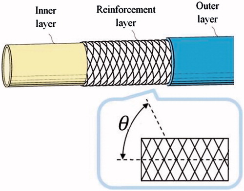
The pushability, torqueability, and flexibility of a catheter are, respectively, determined by the axial, flexural, and torsional rigidity. Several studies have evaluated the optimal rigidity values for diagnostic and guiding catheters designed for various endovascular applications [Citation19–25]. As compared to diagnostic catheters, guiding catheters have a stiffer shaft, larger internal diameter, and feature sufficient axial and torsional rigidity, allowing the user to easily push the catheter through the vascular system to control the torque for proper manipulation. The flexural rigidity should be variable, decreasing towards the tip, to allow passage of the catheter through tortuous sections of the cardiovascular system without causing injury to the arterial wall [Citation25]. For these reasons, composite tube designs using more plastic materials are usually employed. Moreover, braided structures are commonly used to enhance catheter torqueability. As a result, guiding catheters are generally composed of an inner layer, a reinforcement layer, and an outer layer [Citation26].
In regard to the reinforcement layer, there is a wide variety of braided meshes available from manufacturers with different materials, shapes, sizes, numbers of wires, and braid angles between the longitudinal axis of the mesh and the mesh wires (). Typically, braided meshes with a lower angle exhibit a greater stiffness, while a higher angle has a resistance to kinking of the flexible tube [Citation27].
Figure 2. Example of a guiding catheter structure made of three different layers. The reinforcement layer is comprised of a braided mesh characterized by a braid angle that changes the flexibility and torque response of the catheter.
For our specific application, a three layer braided solution was selected and literature values for braided catheters [Citation25] were considered as target rigidity values ().
Table 1. Target rigidity values for guiding catheters.
For simple tubular structures the axial (EA), flexural (EI), and torsional (GJ) rigidity can be simply calculated as:
(1)
(2)
(3)
Where ro and ri are the outer and inner radii of the tube; A is the cross-sectional area; I and J are the second moment of area and polar moment of inertia; and E and G are the elastic and shear moduli of the tube constructive material.
Estimation of the mechanical properties of multi-layered braided catheters is more complex and can be performed using software based on finite element analysis. In this work, CathCAD (Roth Technologies, San Antonio, TX, USA), a commercially available software to predict the mechanical properties of a catheter, was used to identify possible design solutions with the desired mechanical specifications (see Experimental Evaluation - Mechanical Properties Prediction).
Catheter stabilization
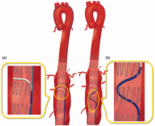
Two design solutions to achieve a stable catheter positioning at the target fenestration site were defined: the first solution was inspired by the design of a commercial catheter, the Piton™ GC by Medtronic (Minneapolis, MN, USA) [Citation28], while the second was based on a preformed shape of the catheter body to gain support from the graft wall. The Piton™ GC is a carotid guiding catheter featuring a standard front hole and a side hole for the insertion of a 0.035’’ stiff guidewire (referred to as a 'stabilizer'), which is advanced through the aortic arch and maintained in position to provide a strong backup while engaging the external carotid artery. The same concept could be potentially applied to provide stability during fenestration (). The second solution instead consists in pre-shaping the catheter body () in order to increase the contact area between the catheter and the implanted graft. In this way, stability is gained from the reaction forces from the stent graft wall.
Figure 3. Proposed design solutions for catheter stabilization: (a) ‘Piton-like’ catheter employing a stiff guidewire as a ‘stabilizer’; and (b) a design based on a preformed shape of the catheter body to increase the contact area between the catheter and the graft.
Catheter tip bending
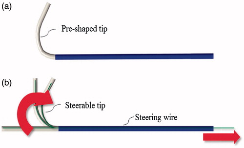
As previously stated, the distal curvature of the guiding catheter should allow the user to accurately place the guidewire tipped laser fiber perpendicular to the graft surface. Two solutions have been adopted to achieve accurate placement based on passive or active bending of the distal end of the catheter. With the passive solution, a pre-shaped guiding catheter with a tip pre-bent by plastic deformation is used. More particularly, an over-bent catheter with a curvature of less than 90° can be adopted. In this case, the flexibility of the catheter tip is selected while taking into account the mechanical properties of the guidewire tipped laser fiber. Flexural rigidity indeed should be properly tuned so that, when the guidewire tipped laser fiber is inserted within the catheter lumen, the final curvature of the catheter is about 90°.
In contrast, with the active solution, the user can actively control the catheter tip with a steering mechanism. Cable actuation is currently employed in steerable catheters. Different bending angles can be obtained by varying the extension of the pull wire, while the degrees of freedom (DOFs) can be increased by employing multiple pull wire pairs [Citation29]. Traditionally, pull wires are slidably disposed within a dedicated lumen of the catheter and fixed adjacent to the distal end of the catheter. The opposite ends of the pull wires instead are secured to a control member (e.g., a slider) mounted to the catheter handle, so that manipulation of the latter translates into predictable catheter bending.
In this study, both solutions, passive and active, were taken into account. More particularly, a pre-shaped tip, as shown in , and a steerable catheter with an orientation control of 1 DOF (catheter bending in a single plane) was evaluated by endovascular experts (as described in the Experimental Evaluation section) to define an optimal solution.
Figure 4. Proposed design solutions for catheter tip bending: (a) a passive solution with a pre-shaped tip and (b) an active solution with a steerable tip.
Sensorization
Essential features to achieve accurate targeting of the fenestration site include accurate real-time tracking of the catheter tip and reconstruction of the catheter distal curvature to ease catheter EM navigation [Citation10]. In this work, the sensorization and calibration strategies described in [Citation11] were employed and two minute 5 DOFs EM sensor coils (0.3 × 13 mm) (Aurora, Northern Digital, Waterloo, Canada) were integrated into the distal portion of the catheter. Moreover, as a precautionary measure, an additional 5-DOFs sensor was integrated into the catheter tip to refine the calibration [Citation30]. For this reason, the guiding catheter should include two accessory lumens for sensors (). In this work, the cross-sectional dimensions of these lumens were defined in order to minimize the total structural dimensions, while still allowing easy insertion of the sensor coils. A circular lumen, 0.6 mm in diameter, was chosen after sensorization trials.
Figure 5. Possible configuration of sensors. Sensor 1 and 2 are positioned according to the method proposed in [Citation11]. Moreover, Sensor 3 is integrated into the catheter tip as a precautionary measure to refine catheter calibration.
![Figure 5. Possible configuration of sensors. Sensor 1 and 2 are positioned according to the method proposed in [Citation11]. Moreover, Sensor 3 is integrated into the catheter tip as a precautionary measure to refine catheter calibration.](/cms/asset/f9369fc8-d341-48d8-8f70-f85280c24012/icsu_a_1358403_f0005_c.jpg)
Catheter size and length
In the early years of endovascular treatment, guiding catheters were large, bulky, and difficult to handle, leading to high rates of catheter-associated complications [Citation31]. Nowadays, as reported by the 2015 Buyer's Guide of Endovascular Today [Citation32], the size of guiding catheter typically ranges from 5 to 10 F. For our particular application, there were no particular restrictions on maximum size, considering that the profile of currently available components of endograft delivery systems ranges from 9 to 25 F in inner diameter (ID), which correlates to an outer diameter (OD) of about 11 to 27 F [Citation33]. The minimum size of our guiding catheter instead was based on the size of the guidewire tipped laser fiber and the size of the 'stabilizer' (the latter was only for the Piton™ catheter), which determine the minimum ID. The diameter of the pull wire (for the steerable solution), the size of the sensor lumen, and the width of the braided matrix impose a limit on the width of the catheter wall. The catheter length instead can range from 65 to 80 cm, depending on the specific anatomy of the patient, as the dimensions of selective catheters for renal artery interventions [Citation34].
2.2 Experimental evaluation
This section describes an in vitro test performed to preliminary evaluate the stabilization and bending of the proposed catheter. Moreover, methods employed to predict the mechanical properties and to choose fabrication materials, braiding parameters, and catheter sizes (layer thickness) of the catheter are described.
In vitro tests
In this study, endovascular surgeons and interventional radiologists were asked to test the design solutions proposed for catheter stabilization ('Piton-like' vs. 'pre-shaped body') and bending ('over-bent tip' vs. 'steering tip'). The aim of these tests was to receive preliminary feedback from physicians in order to guide the design process toward an optimal configuration and to rapidly and economically test elements that are most likely to generate problems related to the difference between the perspectives of the designed and user.
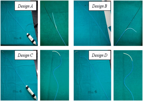
Four catheter designs () were tested: design A is a ‘Piton-like’ catheter with a steerable tip; design B is a ‘Piton-like’ catheter with an over-bent tip; design C is a catheter with a pre-shaped body and a steerable tip; and finally design D is a catheter with a pre-shaped body and an over-bent tip. All of the catheter prototypes were obtained by modifying a 5.5 F Orienter (Angiologica B.M. S.r.l, San Martino Siccomario PV, Italy), a guiding catheter with a 1 DOF steerable tip [Citation35]. This catheter set, which includes all possible combinations of the proposed stabilization and bending systems, was used for a proof of concept demonstration to assess whether these solutions are reasonable and intuitive for surgeons.
Figure 6. Preliminary prototypes of the four design solutions to test the stabilization and bending systems. Two pictures are reported for each prototype: a global view of the catheter on the left and a zoom detail of the catheter distal part on the right. The two steerable catheters (Designs A and C) have a handle to actively control bending of the tip.
A 300 cm long 0.035’’ Lunderquist® Extra Stiff Wire Guide (Cook Medical, Bloomington, IN, USA) was used as a ‘stabilizer’ for testing of designs A and B. A diameter of 0.035’’ was chosen according to the Piton™ GC Instructions for Use in order to guarantee sufficient mechanical support. A 0.035’’ Radifocus® Guidewire (Terumo Interventional Systems, Somerset, NJ, USA), which has a more flexible distal end, was instead used for navigation of design C and D catheters.
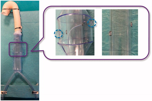
The in vitro set-up was comprised of a simple aorta simulator, which included an infrarenal aneurysm and a plastic tube, with two fenestration targets, to simulate the stent graft. The plastic tube is inserted within the simulated aneurysm, with targets aligned to the renal ostia (). Both the aorta simulator and the plastic tube are composed of clear transparent material to allow the operator to navigate the catheter under direct vision.
Figure 7. In vitro set-up. A global view of the aorta simulator is shown on the left and a zoom detail showing the plastic tube inserted into the aorta mannequin to simulate the stent graft is shown on the right. Two metal rings are used to indicate the target fenestration sites aligned to the simulated renal ostia (highlighted with blue dotted circles). Note that the plastic tube has no holes at the metal rings.
To assess the different solutions, the operators were asked to reach the two designated targets within the simulated aneurysm. More particularly, each operator was asked to perform the targeting task both from the right and left femoral access (for a total of 4 targeting procedures). For analytical purposes, the participants were divided into three groups on the basis of experience in endovascular procedures. The 'low experience' group consisted of eight subjects who had performed less than 20 endovascular procedures as the primary operator, the 'medium experience' group included four operators who had performed between 20 and 100 procedures, and finally the 'expert' group consisted of three subjects who had performed more than 100 endovascular procedures. Before starting the study, all participants received the same standardized instructions on in situ fenestration and an explanation of how to use each catheter.
At the end of the experimental session, the participants were asked to complete a questionnaire to evaluate the four design strategies. The questionnaire was comprised of 9 items that were assessed using a 5-point Likert scale (1 = strongly disagree and 5 = strongly agree) grouped under two headings: design solution evaluation and general evaluation of stabilization and bending. The first item group () was administered for each catheter prototype. Then, after evaluation of each design, the participants were asked to express their level of agreement with the general statements (second item group) regarding the stabilization and bending systems (). Statistical analysis of data was performed using SPSS® Statistics Base 19 software (SPSS, Inc., Chicago, IL, USA). The central tendencies of responses to a single Likert item were expressed as medians, with dispersion measured by interquartile range. The Wilcoxon signed-ranks test was used to determine the significance of the responses to each item to evaluate if the participants were significantly more likely to agree or disagree with each of the statements. A probability (p) value <0.05 was considered statistically significant.
Table 2. Likert Questionnaire: design solution evaluation. For each item, median values with interquartile range (IQR) (25th; 75th) relative to the four proposed design solutions are reported.
Table 3. Likert Questionnaire: general evaluation of stabilization and bending. Median values with interquartile range (IQR) (25th; 75th) are reported.
In addition to the Likert questionnaire, the operators were also invited to respond to an open question to address any further comments/observations.
Mechanical properties prediction
CathCAD®, a validated software that includes a comprehensive material and braid wire database, was used to test several fabrication materials, braiding parameters, and geometries. The employed computational algorithms are based on mechanics of composite materials and composite laminate theory [Citation36,Citation37]. Different solutions were analyzed in order to obtain catheters with variable flexural stiffness (flexibility increasing toward the catheter tip), in consideration of the rigidity ranges reported in [Citation25] as target values. More specifically, a three-layer braided design was considered and the following plastic materials, commonly employed for endovascular catheter fabrication, were selected: Pellethane® 2363 series (Lubrizol Corporation, Wickliffe, OH, USA), Pebax® 33 series (Arkema Inc., Philadelphia, PA, USA), and TEFLON® polytetrafluoroethylene (PTFE) (DuPont Corp., Wilmington, DE, USA).
Pellethane® 2363 is a thermoplastic polyurethane elastomer, available at various hardness: 55 D and 65 D are the most commonly used shores for medical catheters. This material has excellent hydrolytic stability, is resistant to fungi and microorganisms, and has an exceptionally smooth surface. The coefficient of friction of Pellethane® can be further reduced by the addition of hydrophilic polymers, such as polyethyl oxazoline. Pebax® is a thermoplastic elastomer composed of rigid polyamide blocks and soft polyether blocks. Its composition (the block types and ratios) can be varied to achieve a wide range of mechanical properties: the flexural modulus range offered by the Pebax® 33 series ranges from approximately 10 to 500 MPa [Citation38]. Finally, TEFLON® PTFE is the most common lining materials for multi-lumen tubing and is often combined with an outer jacket composed of Pebax® [Citation39–43]. An austenitic non ferromagnetic steel, 304 V stainless steel, was selected as a braiding material to prevent interference with the EM localization system. More specifically, a braiding configuration with 32 round wires 0.02 mm in diameter was selected and various braid angles were tested.
The following strategies were considered to finely tune the mechanical properties of the catheter:
Changing the braiding properties by varying the braid angle from 20° to 70°.
Changing the hardness of the employed materials.
For the Pebax® 33, hardness shore values of 25 D, 35 D, 40 D, and 55 D were tested. For the Pellethane® 2363, hardness shore values of 55 D and 65 D shores were considered.
The catheter size and geometry were defined according to the surgeon feedback after analysis of the in vitro tests results (, in the Results section, represents two cross sections of the tested catheter design).
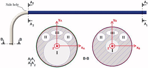
Figure 8. Possible cross-sectional views ('A1-A1, ' 'A2-A2, ' and 'B-B') at positions A1, A2, and B, of a design A catheter. Four lumens are shown: a central operative lumen (I) for the guidewire tipped laser fiber and the 'stabilizer', two lumens for EM sensors (II), and a lumen for the steering cable (III). The cross section A1-A1 is constant in the catheter blue portion. Then, after the side hole for the 'stabilizer, ' tapering of the central operative lumen (I) as well as the catheter external diameter was started. Two coordinate systems (XAYAZ and XBYBZ, respectively) used for calculation of the second moment of area (Ixx, Iyy, Jzz) at 'A1-A1' and 'B-B' are represented.
3. Results
The main tendencies (median and interquartile range) of responses to each Likert item are shown in and . Statistically significant results (p < 0.05) are highlighted in bold font.
Based on the overall scores, we conclude that design A, a 'Piton-like' catheter with a steerable tip, was most preferred by the surgeons. As shown in , there was overall significant agreement that design A allows the catheter to be easily advanced, the catheter tip to be properly guided and aligned to the target, the catheter to be maintained in a stable position during fenestration, and the catheter to be used for cannulation of renal arteries after the fenestration procedure. Moreover, the obtained data show that, from the perspective of users, design A also allows the catheter to be easily rotated (median score =4). For this particular design, the overall scores are in agreement with the experts' opinions, with the exception of the score for item 6, for which the expert group expressed a neutral opinion about the possibility of also using the catheter for cannulation of the renal arteries. However, a larger study with a greater number of experts is required for statistical evidence in this group.
As suggested by the results presented in , none of the proposed design enabled the user to reach both fenestration targets without changing the catheter access, which means that only one fenestration will be accessible from a given iliac vessel at one time. Nevertheless, as pointed out by the expert surgeons, the possibility of using a unilateral access should not be considered a critical feature, since endovascular procedures often require a bilateral femoral approach.
Considerations of design A, emerging from (item 1:6, design solution evaluation), are confirmed by responses to items 7 and 9 (general evaluation of stabilization and bending), which are summarized in . Each group agreed that the use of a 'stabilizer' allows a stable positioning of the catheter and active bending of the catheter tip is useful to easily reach the fenestration target.
shows possible cross sections at positions A1, A2, and B of a design A catheter with a 9 F shaft. The proposed catheter is composed of three layers and four lumens: a central operative lumen (I) for the guidewire tipped laser fiber and the 'stabilizer', two lumens for EM sensors (II), and a lumen for the steering cable (III).
The central operative lumen tapers from a diameter of 1.85 mm (to accommodate both the guidewire tipped laser fiber and the 'stabilizer') at the proximal end (A1 and A2 cross sections), to a diameter of 0.93 mm (to accommodate only the guidewire tipped laser fiber) at the distal end (B cross section).
Given the geometric parameters of the selected catheter design, several simulations were performed as previously described in the 'Mechanical Properties Prediction' paragraph, i.e., changing braiding properties and layer materials. As shown in , two solutions were selected among all of the simulations with flexural (EIxx, EIyy), axial (EA) and torsional (GJzz) rigidities compatible with the target values in the literature ().
Table 4. Mechanical simulations for two different solutions.
For both solutions, rigidities values of three portions corresponding to sections A1, A2, and B () are reported. The area and second moment of area (Ixx, Iyy, Jzz) of the inner layer is reported together with the thickness of the reinforcement and outer layers. In the first solution, PTFE is used as a lying material and Pebax® 3335 (35 D) is employed for the reinforcement and outer layers. In the second solution, all of the catheter layers are made of Pellethane® 2363-55 D.
In both solutions, the braiding angle (BA) of the reinforcement layer increases from A1 to A2 (from 50° to 60°) and from A2 to B (from 60° to 65°) to reduce the flexural rigidity toward the tip side of the catheter. However, despite this braiding angle variation, in the first solution, flexural rigidity was greater in section B than A1 (see ) because flexural rigidity is dependent on the second moment of area (EquationEquation (2)(2) ). The latter indeed increases towards the catheter tip due to the tapering of the central operative lumen. In the second solution, the inner layer is made of Pellethane® 2363-55 D, which has a lower stiffness than TEFLON® PTFE (flexural modulus equal to 0.172 vs. 0.496 MPa). Thus, despite the increase in the second moment of area, the contribution of the braiding angle is sufficient to reduce the flexural modulus. For this reason, the second solution was selected for the final design of the catheter.
4. Conclusion
This work represents the first step toward the development of a 3 D EM navigation platform for the guidance of an innovative endovascular procedure to repair an abdominal aortic aneurysm via in situ laser fenestration of a traditional stent graft. The idea behind this work is to integrate a laser system into a 3 D EM navigation platform to provide the surgeon with a selective fenestration tool that can be accurately tracked and shown within the 3 D model of the patient vasculature. This work focuses on the sensorized guiding catheter for the navigation and positioning of the laser tool in correspondence to the fenestration site. These preliminary results demonstrated the clinical reasonability and feasibility of the designed tool in terms of mechanical properties.
Based on the surgeon feedback, a 9 F ‘Piton-like’ catheter with a steerable tip was designed. The proposed catheter features a steering cable to actively control the catheter distal curvature, a central operative lumen for the laser device and a side hole for the insertion of a 'stabilizer', and 5 DOFs EM coils for real-time tracking of the catheter. The availability of a steerable guiding catheter will allow the user to place the laser fiber tip perpendicular to the graft surface as required for optimal stent graft fenestration. Moreover, after the fenestration procedure, it could also allow to operator to adjust the bending angle to properly cannulate the collateral artery.
The simulations performed with CathCAD®, a commercially available software for catheter design, demonstrated the technical feasibility of the proposed design in terms of mechanical specifications. More specifically, a three-layered braided design, with a braid angle increasing from 50° to 65° toward the tip side of the catheter, was selected to achieve flexural, axial, and torsional rigidities compatible with the target values in the literature. Pellethane® 2363-55 D was chosen as the material to construct the catheter tubing and 304 V stainless steel, an austenitic non-ferromagnetic steel, was selected as a braiding material to prevent electromagnetic interference with the localization system.
One limitation of this study is the relatively small number of surgeons involved in the trial. However, the aim of this work was to rapidly and economically test elements that are most likely to generate problems related to the difference between the perspectives of the user and designer.
In vitro tests were performed using early catheter prototypes and a very simple vascular simulator to receive a preliminary surgeon feedback regarding the proposed solutions for catheter stabilization and bending.
This study represents the starting point of an iterative process with the purpose to guide the design toward the preferred solutions of the surgeon, which will include in vitro tests with improved materials and more realistic simulators with different anatomical variants. The next step will be the manufacturing of catheters according to the user feedback and the mechanical specifications listed in this work. Future studies will include accurate mechanical testing of the obtained catheter according to the methods proposed in the literature [Citation24,Citation25]. In vitro testing, involving a larger number of surgeons and using a simulator with a more realistic anatomical shape, will be performed for a further validation of the catheter prior to animal testing [Citation44]. Moreover, simulated blood flow will be considered for quantitative evaluation of the catheter stability in a realistic scenario.
Disclosure statement
The authors report no conflicts of interest. The authors alone are responsible for the content and writing of this article.
Additional information
Funding
References
- Crawford ES, Beckett WC, Greer MS. Juxtarenal infrarenal abdominal aortic aneurysm. Special diagnostic and therapeutic considerations. Ann Surg. 1986;203:661–670.
- Ricotta JJ II, Oderich GS. Fenestrated and branched stent grafts. Perspect Vasc Surg Endovasc Ther. 2008;20:174–187.
- Chuter TA. Fenestrated and branched stent-grafts for thoracoabdominal, pararenal and juxtarenal aortic aneurysm repair. Semin Vasc Surg. 2007;20:90–96.
- Chuter TA. Branched and fenestrated stent grafts for endovascular repair of thoracic aortic aneurysms. J Vasc Surg. 2006;43(Suppl A):111A–115A.
- McWilliams RG, Fearn SJ, Harris PL, et al. Retrograde fenestration of endoluminal grafts from target vessels: feasibility, technique, and potential usage. J Endovasc Ther. 2003;10:946–952.
- Ahanchi SS, Almaroof B, Stout CL, et al. In situ laser fenestration for revascularization of the left subclavian artery during emergent thoracic endovascular aortic repair. J Endovasc Ther. 2012;19:226–230.
- Lin J, Udgiri N, Guidoin R, et al. In vitro laser aortic and thoracic stent graft fenestration for urgent treatment of aortopathies. J Vasc Surg. 2014;60:1398.
- Murphy EH, Dimaio JM, Dean W, et al. Endovascular repair of acute traumatic thoracic aortic transection with laser-assisted in-situ fenestration of a stent-graft covering the left subclavian artery. J Endovasc Ther. 2009;16:457–463.
- Redlinger RE Jr, Ahanchi SS, Panneton JM. In situ laser fenestration during emergent thoracic endovascular aortic repair is an effective method for left subclavian artery revascularization. J Vasc Surg. 2013;58:1171–1177.
- Condino S, Calabro EM, Alberti A, et al. Simultaneous tracking of catheters and guidewires: comparison to standard fluoroscopic guidance for arterial cannulation. Eur J Vasc Endovasc Surg. 2014;47:53–60.
- Condino S, Ferrari V, Freschi C, et al. Electromagnetic navigation platform for endovascular surgery: how to develop sensorized catheters and guidewires. Int J Med Robot Comput Assist Surg. 2012;8:300–310.
- Sidhu R, Weir-McCall J, Cochennec F, et al. Evaluation of an electromagnetic 3D navigation system to facilitate endovascular tasks: a feasibility study. Eur J Vasc Endovasc Surg. 2012;43:22–29.
- Pujol S, Pecher M, Magne JL, et al. A virtual reality based navigation system for endovascular surgery. Stud Health Technol Informat. 2004;98:310–312.
- Zhang L, Parrini S, Freschi C, et al. 3D ultrasound centerline tracking of abdominal vessels for endovascular navigation. Int J Cars. 2014;9:127–135.
- Parrini S, Zhang L, Condino S, et al. Automatic carotid centerline extraction from three-dimensional ultrasound Doppler images. Conf Proc IEEE Eng Med Biol Soc. 2014;2014:5089–5092.
- Turini G, Condino S, Postorino M, et al. Improving endovascular intraoperative navigation with real-time skeleton-based deformation of virtual vascular structures. Augmented reality, virtual reality, and computer graphics: Third International Conference, AVR, Lecce, Italy, June 15-18, Proceedings, Part II; 2016. p. 82–91.
- Moore WS, Ahn SS. Endovascular surgery. Philadelphia (PA): Saunders; 2001.
- Sonesson B, Dias N, Resch T, et al. Laser Generated In situ Fenestrations in Dacron Stent Grafts. Eur J Vasc Endovasc Surg. 2016;51:499–503.
- Stenqvist O, Curelaru I, Linder LE, et al. Stiffness of central venous catheters. Acta Anaesthesiol Scand. 1983;27:153–157.
- Bersten AD, Williams DR, Phillips GD. Central venous catheter stiffness and its relation to vascular perforation. Anaesth Intensive Care. 1988;16:342–351.
- Martin RW, Johnson CC. Engineering considerations of catheters for intravascular ultrasonic measurements. Proceeding of SPIE, Catheter-Based Sensing and Imaging Technology; 1989.
- Wunsche P, Werner C, Bloss P. Bending stiffness of catheters and guide wires. Biomed Tech Biomed Eng 2002;47(Suppl 1):150–153.
- Eckmann DM. Variations in epidural catheter manufacture: implications for bending and stiffness. Reg Anesth Pain Med. 2003;28:37–42.
- Carey J, Emery D, McCracken P. Buckling test as a new approach to testing flexural rigidities of angiographic catheters. J Biomed Mater Res Part B Appl Biomater. 2006;76:211–218.
- Carey J, Fahim A, Munro M. Design of braided composite cardiovascular catheters based on required axial, flexural, and torsional rigidities. J Biomed Mater Res. 2004;70:73–81.
- Mishra S, Bahl VK. Curriculum in cath lab: coronary hardware: part I the choice of guiding catheter. Indian Heart J. 2009;61:80–88.
- Kocaturk O, Saikus CE, Guttman MA, et al. Whole shaft visibility and mechanical performance for active MR catheters using copper-nitinol braided polymer tubes. J Cardiovasc Magn Reson. 2009;11:29.
- Piton™ GC [Internet]. Minneapolis (MN): Medtronic. [cited 2017 Feb 15]. Available from: http://www.peripheral.medtronicendovascular.com/international/product-type/carotid-package/piton-gc/index.htm
- Fu YL, Liu H, Huang WT, et al. Steerable catheters in minimally invasive vascular surgery. Int J Med Robot. 2009;5:381–391.
- Condino S, Piazza R, Micheletti F, et al. Electromagnetic guided in-situ laser fenestration of endovascular stent-graft: endovascular tools sensorization strategy and preliminary laser testing. Lect Notes Comput Sci. 2016;9805:72–83.
- Udaya Prashant P. Current and emerging catheter technologies for percutaneous transluminal coronary angioplasty. Res Rep Clin Cardiol. 2014;5:213–226.
- Endovascular Today’s 2015 Buyer’s Guide [Internet]. Wayne (PA): Bryn Mawr Communications Ii, Llc. [cited 2017 Feb 15]. Available from: http://evtoday.com/buyers-guide/2015/chart.asp?id=guiding_catheters
- Arslan B, Turba UC, Sabri S, et al. Current status of percutaneous endografting. Semin Intervent Radiol. 2009;26:67–73.
- Schneider P. Endovascular skills: guidewire and catheter skills for endovascular surgery. 2nd ed. Boca Raton (FL): CRC Press; 2003.
- Orienter [Internet]. Pavia (Italy): Angiologica B.M. S.r.l.; [cited 2017 Feb 15]. Available from: from: http://www.angiologica.com/catetere-orientabile-orienter.
- Jones RM. Mechanics of composite materials. New York: Scripta Book Company; 1975.
- Richardson D. The fundamental principles of composite material stiffness predictions [Internet]. [cited 2017 Feb 15]. Available from: https://sedyono.files.wordpress.com/2016/01/property-prediction.pdf.
- Pebax® [Internet]. High Wycombe, Buckinghamshire: RESINEX Group. [cited 2017 Feb 15]. Available from: http://www.resinex.co.uk/products/pebax.html.
- Rosenman D, Kayser D, Keleher M, et al. Inventors; Biocardia, Inc., Assignee. Steerable guide catheters and methods for their use. 2004.
- Dinh JQ, Valko JJ, Strauss BM, et al. Inventors; Reverse Medical Corporation, Assignee. Microcatheter with modified PTFE liner. 2013.
- Ross CD. Inventor; Engineering Resources Group In, Assignee. Guide catheter. 2004.
- Lentz DC. Inventor; Cook Incorporated, Assignee. High pressure infusion catheter. 2008.
- PTFE Lined Braided Stent Delivery Catheter [Internet]. Glens Falls (NY): Precision Extrusion Inc. [cited 2017 Feb 15]. Available from: http://www.precisionextrusion.com/composite_tubing.html
- Sinceri S, Carbone M, Marconi M, et al. Basic endovascular skills trainer: a surgical simulator for the training of novice practitioners of endovascular procedures. Conf Proc IEEE Eng Med Biol Soc. 2015;2015:5102–5105.