
Abstract
Nowadays, sparse representation has been widely used in Magnetic Resonance Imaging (MRI). The commonly used sparse representation methods are based on symmetrical partition, which have not considered the complex structure of MRI image. In this paper, we proposed a sparse representation method for the brain MRI image, called GNAMlet transform, which is based on the gradient information and the non-symmetry and anti-packing model. The proposed sparse representation method can reduce the lost detail information, improving the reconstruction accuracy. The experiment results show the superiority of the proposed transform for the brain MRI image representation in comparison with some state-of-the-art sparse representation methods.
1. Introduction
In recent years, the Magnetic Resonance Imaging (MRI) image has been increasingly used in computer aided brain structure and function studies and it plays a more and more important role in computer aided diagnosis [Citation1]. The MRI image works better than the Computer Tomography (CT) image in demyelinating diseases (such as multiple sclerosis), because the ectocinerea and the alba could be clearly distinguished in it. Also, the MRI image is the first choice for brainstem and cerebellum lesions because of no artifacts in it.
With the development of the artificial intelligence, the sparse representation has been widely applied to MRI image analysis and process. However, limited examples and high dimensional features induced over-fitting and redundancy features are two problems prevent MRI image from moving forward. Sparse representation [Citation2–4] gives a solution to this problem without any hardware changes. To mine the deep information and to develop new representation and processing method for MRI image are the keys to the brain science and computer-aided diagnosis.
The wavelet transform was one of the most widely used sparse representation method, which could usually obtain much sparser representation to the point-singularity signal than other representation methods. However, it was inefficient to represent the contours and edges of the image. Given this, a lot of multi-scale geometric analysis methods with more directional sensitivity have been proposed to improve the treatment of the orientated geometric image structures. Such as the ridgelet transform [Citation5], the curvelet transform [Citation6] the contourlet transform [Citation7], the shearlet transform [Citation8], the directionlet transform [Citation9], the wedgelet transform [Citation10], the bandelet transform [Citation11], the grouplet transform [Citation12], the easy path wavelet transform (EPWT) [Citation13], and the directional lifting-based wavelet transform [Citation14] et al.
In order to protect image details, the quadtree method [Citation15] and the tetrolet transform [Citation16] are proposed. In the tetrolet transform, the image was firstly divided into some 4 × 4 blocks. In each of these blocks, the optimal partition of the block according to the geometry of the image was computed. Then, the wavelet transform was applied into each block of the image. The quadtree and the tetromino are symmetric blocking methods to some extent, which has not considered the structural information of the image fully. The Non-symmetry and Anti-packing Model (NAM) [Citation17] is an inverse problem of the packing problem. The concept of non-symmetry means that the structure of anti-packing is asymmetry. However, if the NAM is applied to the image directly, it would lead to over-segmentation in the brain MRI image due to its complex structural information.
In this paper, we proposed a novel sparse representation method, called GNAMlet transform. Firstly, the NAM is applied to the gradient image, and the gradient image would be partitioned into some non-symmetry blocks. Then, mapping this partition results to the original image, we can get square blocks with unfixed sizes in the original image. Finally, we conduct single layer haar wavelets in these blocks. By using the GNAMlet transform, a more efficient sparse representation method is put forward, which can reduce the lost detail information and improve the reconstruction accuracy.
The paper is organized as follows. In Section 2, we review the NAM method in brief, and give a detailed description of our proposed GNAMlet transform. And we compare the GNAMlet transform with other existing sparse representation methods in Section 3. Finally, the conclusion and discussion are drawn in Section 4.
2. Sparse representation based on the GNAMlet transform
2.1. The brief description of NAM
The basic idea of NAM can be described as follows: Given N pre-defined sub-patterns and one packed pattern, pick up all of the homogeneous blocks from the packed pattern and then combine these homogeneous blocks to approximate the original packed pattern. Mathematically, the NAM can be defined as a transform T mapping from pattern F to F′, which can be written as follows:
(1)
and
(2)
where, Fi′ and Fj′ are the ith and jth homogeneous blocks respectively, v is the value of the homogeneous blocks Fi′, A is the parameter set of the homogeneous block Fi′, and ar(r=1,2,⋯mi) is the shape parameter set of Fi′, and δ is the residue pattern. In our work, we use the distortion patterns, thus δ=0 and F′=F.
2.2. The proposed GNAMlet transform
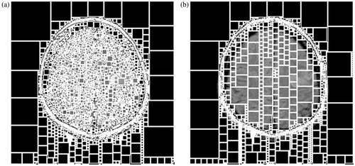
As for a brain MRI image (), there exists rich detail information. If such an image is divided directly by the NAM, too many single points will be obtained in segmentation results, as shown in . Although these adjacent pixels are with little difference, they may be in different blocks and many of these blocks are sized 1×1.
Figure 1. The brain MRI images.
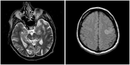
Figure 2. The partition results by using the NAM. (a) NAM based on the gray information, (b) NAM based on the gradient information.
In order to void over-segmentation, we introduce the gradient image and propose a novel sparse representation method. The detail steps are presented below:
Step 1: Obtaining the gradient image. In the gradient image, the value of each pixel is calculated by using the following formula,
(3)
where, u presents the image, gra(u) is the gradient image, ∇xui,j and ∇yui,j represent the horizontal and vertical gradient components of pixel ui,j, respectively, and they are obtained by the following expressions,
(4)
Divide the gradient image into a number of blocks with different sizes by using NAM method, and all the pixels in each block are in the same bit-plane.
Step 2: Mapping this partition result to the original image, and then many square blocks with unfixed size can be obtained in original image (see ).
Step 3: For each block obtained in Step 2, we do the single layer two-dimensional haar wavelet transform and then, the low frequency coefficient and high frequency coefficients are obtained.
Step 4: After finding a sparse representation in each block, we obtain the low frequency coefficients and high frequency coefficients. Then, a certain number of the largest wavelet coefficients are retained by setting a threshold.
3. Experiment evaluation
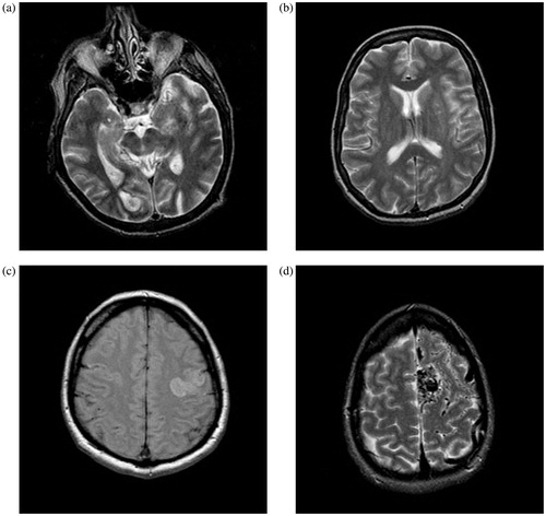
In this section, we will compare the GNAMlet transform with some state-of-the-art methods, such as the biorthogonal 9-7 filter (b9-7, for short), the contourlet transform [Citation7], the tetrolet transform [Citation16], and the quadtree based method [Citation15]. To show the performance of these methods, four test images (sized 256 × 256) are used, which are shown in . Typically, our experiments have been performed on a 3.0 GHz Pentium Dual core computer with 4GB RAM. The operating system is Ms-Windows 7.0 running MATLAB r2015a environment.
Figure 3. Four test images used in our experiments.
For the image with size N×N, where N = 2 J, in b9-7 filter, the image was decomposed into log2(N)-1 levels. For the computation of the contourlet transform, the MATLAB toolbox in http://www.ifp.illinois.edu/∼minhdo/software/ was used. The tetrolet transform used low frequency coefficients from the coarsest level to reconstruct images. And in Ref. [Citation15], there was a threshold used to determine the degree of quadtree decomposition. Thus, for fair comparison, two decomposition levels were selected in the tetrolet transform, and the threshold used in the quadtree decomposition was selected to obtain almost the same number of blocks as the GNAMlet.
3.1. Experiment results
In the following experiments, we will show the nonlinear approximate performance of different transforms by using the four images shown in as test images. In the experiments, for a given value η, we select the η-most significant coefficients in each transform domain, and η is set as 500, 1250 and 2500 respectively in this subsection. Then we compare the reconstructed results from these sets of coefficients, and the standards for evaluating the reconstruction quality are the Peak Signal to Noise Ratio (PSNR) values, the visual quality of the reconstructed results and the error images. Note that in the error images, brighter pixel represents larger error.
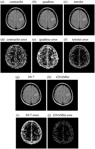
and show the reconstructed images obtained by different methods and the corresponding error images. and are the reconstructed images by using the contourlet transform, the quadtree method, the tetrolet transform, the b9-7 filter and the proposed GNAMlet transform, respectively. and are the corresponding error images. We can see from these figures that there is great amounts of reconstruction error in the results obtained by the contourlet transform, the tetrolet method, the quadtree method, and the b9-7 filter. Compared with these methods, the error images corresponding to the GNAMlet transform has less bright pixels. The gradient image is partitioned into non-symmetry homogeneous blocks by using the NAM, and this partition result is mapped to the original image. Hence the structures can be preserved better.
Figure 4. Nonlinear approximation by using different methods. In the first line and third line, the image is reconstructed from 500-most significant coefficients, and the corresponding error images are presented in the second line and forth line. Brighter pixel represents larger error in error images.
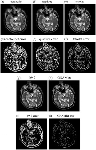
Figure 5. Nonlinear approximation by using different methods. In the first line and third line, the image is reconstructed from 1250-most significant coefficients, and the corresponding error images are presented in the second line and forth line. Brighter pixel represents larger error in error images.
shows the PSNR values of these images by using different methods with η = 500, η = 1250, and η = 2500, respectively. According to this table, we can see that the reconstructed images obtained by the GNAMlet transform get the highest PSNR values under the same most significant coefficients, which is consistent with the visual results in and . Obviously, the GNAMlet transform obtains the best reconstruction quality.
Table 1. The PSNR values obtained by different methods with η = 500, η = 1250 and η = 2500 respectively.
3.2. Computational complexity analysis
Our test was based on 3.0 GHz Pentium Dual core computer with 4GB RAM. The routines were tested in MATLAB. For the image in the subsection 3.1 as reference, we compared the computational efficiency of the decomposition and reconstruction of the GNAMlet transform with the b9-7, the contourlet transform, the tetrolet transform, and the quadtree method, see the following .
Table 2. Comparison of different transforms regarding computation time (in second).
Considering the computation times in , the b9-7, the contourlet and tetrolet transforms achieve shorter computational time. We should note that the b9-7 and the tetrolet transform are based on symmetrical partition, and the fast computation of contourlet transform is based on the usage of C++ programs. Quadtree is most often used to partition a 2 D space by recursively subdividing it into four quadrants or blocks until each quadrant contains only pixels of one color or luminance. Recursively subdividing may result a quadrant that contains only single pixel. Same as the GNAMlet transform, these methods should scan each pixel, therefore, the quadtree and the GNAMlet transform achieve longer computational time.
4. Conclusion and discussion
In this paper, we proposed the GNAMlet transform that could provide a sparse representation for the brain MRI images owning rich structure information.
The detail information preserved power of the GNAMlet transform was based on the following aspects. First, the gradient image is partitioned by using NAM, and then mapping this partition result to the original image, obtaining several non-symmetry blocks in the original image. In these blocks, the single layer two-dimensional haar wavelet transforms are performed. Finally, we could obtain a sparse representation of the image.
Experiment results showed that the proposed GNAMlet transform is indeed a very useful tool in the sparse representation of the brain MRI image. Nevertheless, we would also like to share some limitations of our approach.
First, the NAM partition based on the gradient image generates a large number of small blocks, however in some blocks, such as the blocks obtained along the skull, the information contained is not very useful because people are usually only interested in the brain tissue. Therefore, it takes a lot of computation time to conduct the haar wavelet transform on and to reconstruct the blocks of the skull. In the future, we consider more and better pre-defined sub-patterns to divide the image. And we want to cover the skull with little blocks, thus reducing computation time.
Second, our method is based on the assumption that there exists no noise in the obtained data. In practice, MRI images are normally corrupted by noise during the acquisition process. Therefore, the noise would affect the accuracy of the proposed method, and some details may be lost in reconstruction.
Disclosure statement
No potential conflict of interest was reported by the authors.
Additional information
Funding
References
- Nandakumar HP, Ji J. Sparse representation of complex MRI images. Proceedings of the 30th Annual International Conference of the IEEE Engineering in Medicine and Biology Society; 2008 Aug 20-25; Vancouver, BC; p. 398–401.
- Zhang Z, Xu Y, Yang J, et al. A survey of sparse representation: algorithms and applications. IEEE Access. 2015;3:490–530.
- Chen X, Nguyen BP, Chui C-K, et al. Reworking multilabel brain tumor segmentation: an automated framework using structured kernel sparse representation. IEEE Syst Man Cybern Mag. 2017;3:18–22.
- Bao LJ, Liu WY, Zhu YM, et al. Sparse representation based MRI denoising with total variation. International Conference on Signal Processing. 2008 Oct 26-29; Beijing China; p. 2154–2157.
- Do M, Vetterli M. The finite ridgelet transform for image representation. IEEE Trans Image Process. 2003;12:16–28.
- Cand´es E, Donoho D. New tight frames of curvelets and optimal representations of objects with piecewise c2 singularities. Commun Pure Appl Math. 2004;57:219–266.
- Do M, Vetterli M. The contourlet transform: an efficient directional multiresolution image representation. IEEE Trans Image Process. 2005;14:2091–2106.
- Guo K, Labate D. Optimally sparse multidimensional representation using shearlets. SIAM J Math Anal. 2007;39:298–318.
- Velisavljevic V, Beferull-Lozano B, Vetterli M, et al. Directionlets: anisotropic multi-directional representation with separable filtering. IEEE Trans Image Process. 2006;17:1916–1933.
- Donoho D. Wedgelets: nearly minimax estimation of edges. Ann Statist. 1999;27:859–897.
- Pennec E, Mallat S. Sparse geometric image representations with bandelets. IEEE Trans Image Process. 2005;14:423–438.
- Mallat S. Geometrical grouplets. Appl Comput Harmon Anal. 2009;26:161–180.
- Plonka G. Easy path wavelet transform: a new adaptive wavelet transform for sparse representation of two-dimensional data. Multiscale Model Simul. 2009;7:1474–1496.
- Chang C, Girod B. Direction-adaptive discrete wavelet transform for image compression. IEEE Trans Image Process. 2007;16:1289–1302.
- Khan M, Ohno Y. A hybrid image compression technique using quadtree decomposition and parametric line fitting for synthetic images. IEEE Trans Image Process. 2007;1:263–283.
- Krommweh J. Tetrolet transform: a new adaptive haar wavelet algorithm for sparse image representation. J Vis Commun Image Represent. 2010;21:364–374.
- Liang H, Zhao SR, Chen CB, et al. The NAMlet transform: a novel image sparse representation method based on non-symmetry and anti-packing model. Signal Process. 2017;137:251–263.