
Abstract
Space registration is the primary function of neuronavigation systems. According to the stage of the operation, the registration could be classified as rigid and non-rigid methods. Scientists have proposed three types of rigid registration methods: point-based registration (PBR), line-based registration (LBR), and surface-based registration (SBR). PBR has been widely used in clinical applications. Recently, LBR was proposed as a new spacing registration method. However, the range and accuracy of LBR are still not defined for clinical applications. In this paper, LBR has been evaluated directly with target registration error (TRE) in different operating areas: sphenoid-frontal, parietal-temporal, and occipital areas. We used two head phantoms: elastic and rigid phantoms. After scanning with computerized tomography (CT), the difference between the TRE of the elastic and rigid phantom had been evaluated based on LBR method. Then, LBR had been employed at the rigid phantom using different line patterns: single (100 points), double (200 points), triple (300 points), and quartic lines (400 points). TRE were directly measured on the phantom. Then, t-tests were applied to evaluate the difference between the TRE of LBR of both the phantoms and line patterns. Results indicate that there is no statistical difference in TRE between the phantoms. TRE were reduced to less than 3 mm after the use of double lines which was significantly less than those after the use of single lines. Except for sphenoid tumor, the other operating areas showed statistical differences in TRE between double and triple lines. Except for temporal tumor, the differences between the TRE of triple and quartic lines are not significant.
1. Introduction
To increase surgical accuracy and to reduce the invasiveness of a neurosurgery, surgeons mostly use a neuronavigation system [Citation1]. Preoperative images from CT, MR or ultrasonic (US) would be imported into the systems to display anatomical structures as an image space. During the operation, surgeons used the technique of spatial registration to establish spatial correspondence between the image space and the real patient (physical) space. The neuronavigation system can be used to conduct spatial registration because it could match the physical space to image space automatically, the process is called spatial registration. With the help of spatial registration, the error between the two matched spaces could be less than 3 mm. Using spatial registration, the relative position between surgical tools and the real patient’s anatomy can be mapped and displayed on preoperative images. Therefore, spatial registration is the core technique of a neuronavigation system. Scientists are always performing clinical research studies to determine ways of improving the accuracy of registration in a neuronavigation system.
In literature, scientists have described three kinds of spatial registration methods: point-based registration (PBR), line-Based registration (LBR), and surface-based registration (SBR) [Citation2–4]. The PBR method is based on one-to-one match of fiducials in both the image space and patient space. After locating the corresponding fiducials by PBR method, we develop analytical solutions for spatial registration. Presently, PBR is an important spatial registration method, which is reliable and stable enough to ensure the clinical application of neuronavigation systems [Citation5]. However, the PBR method is complex and expensive process in which preoperative images are attached with artificial fiducial markers and scanned comprehensively. To overcome this limitation, some researchers suggested that spatial registration can be conducted using anatomical landmarks as fiducial points [Citation4]. But anatomical landmarks are never located in a distinct position, the registration accuracy and clinical applications of this method are lower than the PBR method. Furthermore, PBR method is sensitive to the movement of fiducials. On the other hand, it take a lot of time to select corresponding fiducials, and the selection process may be significantly affected by human error.
LBR is a new spatial registration method proposed to overcome the disadvantages of PBR method. Firstly, the head surface of a patient was extracted from preoperative images obtained by performing CT or Magnetic Resonance (MR) scans automatically with neuronavigation system. Secondly, in the physical space, the surgeons used a tracked probe or a laser pointer to draw some lines on the patient’s head. Lastly, these lines were matched with the head surface to obtain the spatial transformation relationship between physical space and image space. Iterative Closest Point (ICP) is a major algorithm used to calculate spatial transformation in both LBR and SBR [Citation6]. Using ICP, spatial transformation relationship between two spaces (patient space and image space) could be obtained under a relative close original position. To obtain a relative close position for the two point set, coarse registration would be employed by PBR method, which is based on several anatomical landmarks. Besides LBR, some researchers suggested SBR as a new rigid spatial registration method. In this method, point cloud of the patient’s head surface was obtained using 3 D laser scanners. However, SBR is seldom used in clinical practice because it should be performed only with additional complex devices, such as laser range scanner (LRS) or stereo video/camera.
TRE is the fundamental metric of accuracy in spatial registration. It is defined as the distance between a target point in one space and its corresponding point in the other space when these points are transformed into the same space after spatial registration [Citation7]. In clinical practice, TRE could not be directly measured because the targets cannot be located exactly. Instead, fiducial registration error (FRE) is usually regarded as an accuracy metric in PBR method; it is the mean value of the distance between corresponding fiducial points after spatial registration [Citation8]. Some papers have described how TRE can be predicted using related information, such as FRE and fiducial point distribution [Citation9], and the practical guidance used for determining the numbers and distribution of fiducial points [Citation10]. In contrast, the LBR method does not have any theoretical information about the distribution of TRE. Moreover, there is not enough practical guidance on how to draw lines for achieving good registration accuracy.
To solve the above problems, our study focused on providing practical guidance on where and how lines should be drawn with a neuronavigation system before performing LBR. The experiments were conducted on a specially designed head phantom.
2. Materials and methods
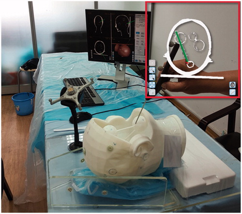
As shown in , we simulated the spatial registration process with two phantoms: (1) a rigid head phantom with brain tumors and (2) an elastic head phantom without tumors. The LBR method was performed on the rigid phantom to determine TRE at different areas of the head, while the elastic phantom was used to simulate the soft tissues in the patient’s deformed face.
Figure 1. Elastic and rigid head phantoms: (a) Elastic phantom, (b) Rigid phantom with tumor models (probe shows the target on tumor model surface).
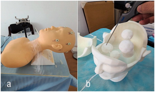
Both the phantoms were scanned by computed tomography (CT). Digital Imaging and Communications in Medicine (DICOM) files were loaded into a neuronavigation system (Fundan digital medicine corp. Shanghai, China) as preoperative images. The cranial head was divided into three operating areas: sphenoid-frontal area, temporal-parietal area, and occipital area. The LBR method would be performed on these areas after completing coarse registration with anatomical landmarks. The TRE of artificial surface markers (elastic phantom) and internal tumor phantoms (rigid phantom) were measured after performing LBR method. Then, t-tests were used to evaluate the difference in the TRE of LBRs performed with different line patterns on the same tumor. The details are explained in the following subsections.
2.1. Rigid head phantom
We designed a rigid head phantom with dimensions of 180 × 190 × 205 mm. The head phantom consists of three parts: frontal-parietal part, occipital part, and face-neck part. These three parts were fixed together with rabbets. There were six brain tumors in the face-neck part, and each tumor was interconnected and supported by three rods. These tumors were located in different areas: 1 sphenoid tumor, 1 frontal tumor, 2 temporal tumors, 1 parietal tumor and 1 occipital tumor; the diameter of the sphenoid tumor was 40 mm while that of others was 50 mm. Every tumor had 32 target points, each of which had a diameter of 2.2 mm and a depth of 1 mm. The rigid phantom was made of photosensitive resin; it was manufactured by rapid prototyping (3 D printing).
2.2. Elastic head phantom
The elastic head phantom was used to simulate the physical properties of a human face. This phantom was made of latex and its dimensions were 145 × 145 × 185 mm. This phantom was only a surface model without tumor. We determined the difference between the point sets extracted from elastic phantom and rigid phantom.
2.3. Division of operating areas
Before performing craniotomy, we defined the operating path (operating area) according to the location of brain tumors and the postures of the patient during operation. Based on this definition, the surface of the cranial head was divided into three areas, and LBR method was performed on each area for assessing the tumors located in one or several areas of the head. The surface of cranial head was divided into the following three areas: (1) sphenoid-frontal area, which includes orbital area, frontal area, and the former portion of temporal area; the sphenoid tumor (pituitary tumor) and frontal tumor were located in this area; (2) parietal-temporal area, which includes the temporal area, the frontal and parietal areas on the same side, and half of the orbital area; the temporal and parietal tumors were located in this area; and (3) occipital area, which includes the occipital area and parietal area; the occipital and cerebellar tumor was located in this area. The LBR method was mainly performed on the corresponding areas of tumors.
2.4. Experiment workflow
illustrates the experimental workflow.
Figure 2. The experimental workflow of LBR method.
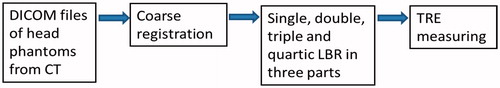
DICOM files containing CT scans of head phantoms
A series of DICOM files contained CT scans of head phantoms; these files were used as preoperative images; each image had a resolution of 512 × 512, with 0.6 mm thickness and 1 mm overlap. We got 480 slices of images for the elastic phantom and 576 slices of images for the rigid phantom. Artificial markers were attached to the phantoms before scanning. Then, the images were loaded into the navigation system, and used to reconstruct 3 D head models.
Coarse registration
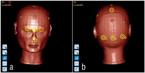
Coarse registration is required for performing LBR method to obtain a relative close original position of the image and physical space. We considered the posture of patient’s head during the operation to classify the anatomical landmarks into two groups. Then, we used these landmarks to perform point-based registration on the following operating areas: (1) sphenoid-frontal area and parietal-temporal area: ①tip of nose, ② the center between the eyebrows, ③ the center of right eyebrow, ④ the center of left eyebrow (); (2) occipital area: ①external occipital protuberance, ② middle point between the external occipital protuberance and the right mastoid process, ③ middle point between the external occipital protuberance and the left mastoid process, ④ middle point between both the sides of parietal protuberance (see ).
Figure 3. Anatomical landmarks selected as fiducials: (a) Sphenoid-Frontal and Parietal-Temporal parts, (b) occipital part.
Single, double, triple, and quartic LBR in three areas
In this paper, we performed the LBR method to study the relationship between line patterns and the TRE in the area of interest. In each operating area, we draw four different line patterns as single line (100 points), double lines (200 points), triple lines (300 points), and quartic lines (400 points). To determine the accuracy of LBR method, we measured the TRE from the target points of tumors (only rigid phantom) and artificial markers (both phantoms). For drawing lines, we had to align the geometric center of a point set on the tumor. This would improve the registration accuracy tremendously. For the three operating areas, we drew the following line patterns:
Sphenoid-frontal part: single line was in the orbital area (see ); the second line was added in the frontal area as double lines (200 points) (); the line on same side of the temporal part was added as triple lines (300 points) (see ); the lines on the other side of the temporal part was added as quartic lines (400 points) (see );
Figure 4. Range of lines for LBR in different areas: row 1 is LBR in Sphenoid-Temporal part: a–d show single(100 points), double (200 points), triple (300 points) and quartic (400 points) lines respectively; row 2 is LBR in Parietal-Temporal part: e–h show single (100 points), double (200 points), triple (300 points) and quartic (400 points) lines respectively; row 3 is LBR in Occipital part: i–l show single once(100 points), double (200 points), triple (300 points) and quartic (400 points) lines) respectively.
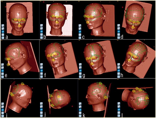
Parietal-Temporal part: single line was in the temporal area (see ); the same side of occipital line was included as double (200 points) lines (see ); the frontal line was considered as triple (300 points) lines (see ); the parietal line was considered as quartic (400 points) lines (see );
Occipital part: single line was in the occipital area as shows; the same side of parietal line was considered as double (200 points) lines as shows; the same side of temporal line was considered as triple (300 points) lines (see ); the other side of temporal line was considered as quartic (400 points) line (see ).
We also recorded surface registration error (SRE) which were calculated automatically in the system after every LBR method. In this case, SRE is the average distance between line point and its closest point on the head surface when they are transformed into the same coordinate system. SRE is an indicator of how well the line fits with the head surface, which is extracted from preoperative images.
Measurement of TRE
A target point on the tumors or fiducials was first selected in the image space, and then the corresponding target point of the phantom was point out with navigation probe. The position of the navigation probe in the physical space was transformed into the image space according to the transformation relationship obtained from LBR. The TRE of the target point was defined as the distance between the transformed pointer’s tip and the previously selected target point of the image as shows.
Figure 5. TRE measurement of corresponding targets both in image and patient space (Frames shows that the probe in the image points to the target on the tumor)
Paired t-tests were used for statistical analysis
To evaluate the difference between the FRE, SRE, and TRE of phantoms and tumors, we performed paired t-tests of statistical analysis using Graphpad software (version 7.0, GraphPad Software, Inc., USA). Box-shape figures were used to depict the difference between single-double, double-triple, and triple-quartic line patterns.
3. Experiments and results
Firstly, we compared the TRE of elastic phantom and rigid phantom; the TRE measurements were performed using LBR. Our aim was to determine the effect of the physical properties of head phantom. Secondly, we want to determine the relationship between line patterns and registration accuracy, LBR would be performed as drawing different line patterns in the three areas of the rigid phantom.
3.1. Difference between the TRE of elastic and rigid phantoms
To explore the difference between the TRE of elastic and rigid phantoms, we performed coarse registration with four fiducials points (anatomical landmarkers) on the sphenoid-frontal area shown in the . This was followed by drawing double lines by LBR on both the phantoms, as shown in ; the process was repeated six times. The TRE measurements were performed twice using five artificial markers on the surface of both the phantoms, and the results are presented in . As shown in , there is no statistical difference (p = 0.569) between the TRE of both the phantoms.
Table 1. Evaluation of TRE by LBR in the elastic and the rigid phantoms (mm).
3.2. TRE after LBR with different patterns of line
After each registration of LBR, we measured the TRE of several target points that were convenient to touch with the probe; these points were located on the corresponding tumor surface. Coarse registration was performed six times on each operating area. For each area, the target points are listed as follows:
Sphenoid-Frontal area: two target points were selected from the sphenoid and frontal tumors, respectively;
Parietal-Temporal area: two target points were selected from the parietal and temporal tumors, respectively;
Occipital area: two target points were selected from the occipital tumor.
shows the FRE of coarse registrations and SRE of LBR for the three operating areas. illustrate the TRE of target points on different tumors and the p value for interval between the following line patterns: single (100 points) and double (200 points) lines, double (200 points) and triple (300 points) lines, triple (300 points) and quartic (400 points) lines.
Figure 6. TRE of sphenoid and frontal tumor phantoms.
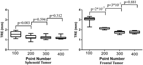
Figure 7. TRE on parietal and temporal tumor phantoms.
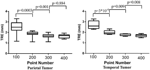
Figure 8. Measurements of TRE of occipital tumor phantom.
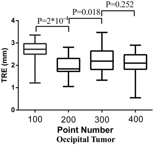
Table 2. FRE of coarse registrations and SRE of LBRs at different areas (mm).
shows that TRE of sphenoid tumor is less than 2.0 mm after single LBR, and its value is stable across different line patterns; however, there is statistical but not prominent difference between the TRE values of single and double lines. The TRE of the frontal tumor reduced significantly after the use of double lines. However, there is statistical difference between the TRE of double and triple lines; the TRE is less than 2.0 mm for triple and quartic lines. No statistical difference was found between the TRE of triple and quartic lines.
shows that the TRE on the parietal and the temporal tumors reduced significantly with the use of double, triple, and quartic lines; the average value of TRE reduced from 2.5 mm to about 2.0 mm following the use of double lines. The average TRE was still around 2.0 mm after the use of triple lines, but the p value had become less than 0.05. After the use of quartic lines, the TRE was similar to that of triple lines on the parietal tumor. There is statistical difference between the TRE of triple lines and quartic lines on the temporal tumor; however, both the TREs are less than 2.0 mm.
shows that the TRE of occipital tumor reduced significantly after the use of double lines, and the average TRE of triple lines was slightly higher than that of double lines. There is no statistical difference between the TRE of triple and quartic lines.
4. Discussion
In this paper, we describe how LBR method must be conducted with neuronavigation system to achieve high registration accuracy at a special neurosurgical target. Our experiments indicated that the proposed areas and the line patterns were suitable for LBR, which is performed on the corresponding tumor area before surgery. In general, the TRE of LBR with double or more lines was significantly smaller than the TRE of LBR with single line; however, the TRE of LBR with triple lines was not significantly different from the TRE of LBR with quartic lines (p > 0.05). For the occipital tumor, the TRE of LBR with triple lines is slightly larger than the TRE of LBR with double lines. This is because when the distance of the line center was far away from the tumor, the registration center would shift to the point where minimal TRE was often achieved.
4.1. How to measure TRE as exactly as possible
TRE cannot be measured exactly because the corresponding points cannot be located accurately both in image and physical space. To make the localization of the corresponding point as accurate as possible, we performed the following two methods:
Average of multiple measurements: the target point was measured several times; the average value of these measurements was used to reduce the localization error caused by single measurement. In this study, the error caused by the localization of the target was reduced by performing 12 measurements on each tumor.
Design distinguishable target points on the phantom: In this study, the target points were small notches with a diameter of 2.2 mm and 1 mm depth. They were easily identified in CT slices of 0.6 mm thickness, and then could also be completely touched with the 2.0 mm tip of the navigation probe (see ) with 0.2 mm error.
4.2. Refining TRE via line range at different operating areas
A universal line pattern was not suitable for all the target regions due to the different postures of patient’s head during the surgery. According the location of brain tumors, we divided the cranial head into three operating areas: sphenoid-frontal area, parietal-temporal area, and occipital area. Then, we demonstrate the line patterns to find suitable line pattern for each of these areas. Because the surgical target location was closer to the single lines as ), the TRE values of sphenoid tumor were less 2 mm. The TRE of frontal tumor became less than 3.0 mm after the inclusion of frontal line (see , ). The TRE of parietal and temporal tumors reduced significantly after the inclusion of orbital line (see , ). The TRE of occipital tumor reduced significantly after the inclusion of parietal line (see , ). The accuracy of LBR became stable after the geometric center of the point set shifted to the corresponding tumor.
4.3. Accuracy of LBR and its potential clinical application
This phantom study was conducted to explore the clinical application of LBR. The accuracy of LBR is evaluated from TRE, which is measured by different methods in many studies; however, all these methods are based on the same principle. Recently, LBR was performed with a tracked pointer in cadaver organs, and the accuracy was 3.25 ± 0.78 mm [Citation11]. Thus, the accuracy of LBR was same as the accuracy of single LBR in this paper. The range of lines was similar to the range of lines shown in . The TRE of LBR in [Citation11] was different from the TRE of LBR in this study; this difference in TRE may be attributed to the use of different algorithms, which should be explored in further works. It should be noted that LBR is less time-consuming than PBR. Moreover, LBR is more stable than SBR. The clinical application of LBR may be considered in the near future provided the line range is confirmed for different operating areas.
5. Conclusions
We divided the cranial head into three areas: sphenoid-frontal area, parietal-temporal area, and occipital area. Then, we determined the line patterns suitable for performing neuronavigation of each area during LBR. The experiment results showed that the proposed division and the corresponding line patterns are suitable for neuronavigation. At the surgical target tumors, the TRE was reduced to approximately 2.0 mm by using double or more lines. In this study, the proposed method was tested on only two head phantoms; however, this method would be tested on real patient in future clinical studies.
Disclosure statement
No potential conflict of interest was reported by the authors.
Additional information
Funding
References
- Paul P, Fleig O, Janni P. Augmented virtuality based on stereoscopic reconstruction in multimodal image-guided neurosurgery: methods and performance evaluation. IEEE Trans Med Imaging. 2005;24:1500–1511.
- Fitzpatrick JM, West JB, Maurer CR. Predicting error in rigid-body point-based registration. IEEE Trans Med Imaging. 1998;17:694–702.
- Eggers G, Mu¨hling J, Marmulla R. Image-to-patient registration techniques in head surgery. Int J Oral Maxillofac Surg. 2006;35:1081–1095.
- Manning W, Zhijian S. Classification and analysis of the errors in neuronavigation. Neurosurgery. 2011;68:1131–1143.
- Fitzpatrick JM, West JB. The distribution of target registration error in rigid-body point-based registration. IEEE Trans Med Imaging. 2001;20:917–927.
- Yifeng F, Dongsheng J, Manning W, et al. A new markerless patient‐to‐image registration method using a portable 3d scanner. Med Phys. 2014;41:1–13.
- Bootsma GJ, Siewerdsen JH, Daly MJ, et al. Initial investigation of an automatic registration algorithm for surgical navigation. Paper Presented at: 30th Annual International Conf. of IEEE Engi. in Medicine and Biology Society. 2008 Aug 20-25; Vancouver, BC, Canada.
- Wiles AD, Peters TM. Real-Time estimation of FLE statistics for 3-D Tracking with point-based registration. IEEE Trans Med Imaging. 2009;28:1384–1398.
- Danilchenko A, Fitzpatrick JM. General approach to first-order error prediction in rigid point registration. IEEE Trans Med Imaging. 2011;30:679–693.
- Manning W, Zhijian S. Improving target registration accuracy in image-guided neurosurgery by optimizing the distribution of fiducial points. Int J Med Rob Comput Assisted Surg. 2009;5:26–31.
- Simpson AL, Burgner J, Glisson CL. Comparison study of interaoperative surface acquisition methods for surgical navigation. IEEE Trans Biomed Eng. 2013;31:1090–1099.