
Abstract
Purpose: A conventional see-through head mount display contains many optical lenses, which can be problematic in image-guided treatment applications due to its size, weight, structure, and focus limitation. Therefore, we have designed a new type of see-through head mount display with a reduced number of optical lenses and an adequate optical resolution that can be utilized for image-guided treatment applications.
Materials and methods: A new type of adjustable focus head mount display with expanded virtual images and an external treatment space that can be provided to the eyes of a user by enlarging the images of a small display is designed and investigated in this study. This type of head mount display can be used in image-guided treatment applications because of the dual paths of imaging and treatment from the optical systems. Therefore, this system with an adjustable focus function can aid doctors in obtaining images for the treatment of the eyes of patients because every patient has a unique pupil size.
Results: The results of the adjustable focus see-through head mount display showed distortion values of +0.36% in the +1 diopter location and −0.55% in the −4 diopter location, and there are less significant modulation transfer function differences within the ±5 diopter locations.
Conclusions: Low optical distortions within ±0.5 diopters can help doctors image the eye conditions of patients through fewer image processing techniques. Therefore, the designed adjustable focus head mount display can provide low optical aberrations and high optical modulation transfer function resolutions for image-guided treatment applications.
Introduction
Recently, various wearable devices such as electrocardiograms, electroencephalograms, oxygen sensors and human–computer interactions have been widely used for medical applications [Citation1–3]. Among these wearable devices, head mount displays (HMDs) are perhaps the most easily approachable and newly emerging products for commercial, educational, and medical applications [Citation4,Citation5]. An HMD can be regarded as a type of viewfinder applied to an optical system such that its optical lens part can easily be separated from the optical system and worn on the human face [Citation6]. Typically, there are two types of HMD systems [Citation7]: see-through HMD systems that allow us to view projected superimposed images as well as provide a real-time view of physical environments, and see-close HMD systems in which us can view the virtual reality screen without viewing physical objects in the display [Citation8]. Compared to the traditional bulky, expensive, and heavy HMDs, current HMD target requires high standards to be small, inexpensive, and light for medical applications because doctors, especially surgeons, generally uses HMDs to integrate several imaging and surgical medical tools [Citation8]. The see-through HMD system is preferable because the see-close HMD system cannot provide a visualization of the target in the display [Citation8]. To use an HMD for image-guided treatment applications, the see-through HMD system must be used because it can simultaneously provide direct projected imposed images and treatment paths from the laser or external sources.
Google introduced a commercial HMD product called the Google Glass. This product provides a narrow field of view (FOV) as of 15° and a low image resolution of 640 × 360 video level of pixels, and it has difficulty in focus adjustment [Citation9]. Minimizing the size, weight and focus adjustment of an HMD design is still significant challenge. Therefore, we developed an HMD that has the smallest size and lightest weight possible and has focus adjustment for imaging and treatment paths. The purpose of this developed HMD to be used together with several other medical appliances together for image-guided treatment applications. Plastic materials are used with less weight and lenses possible with an adjustable focus function.
After considering the proper product HMD size, the system must have an adjustable focus because every doctor and surgeon has different eyesight. Therefore, the developed HMD must have an optical lens within the system that can easily be moved to adjust its focus points if needed while the developed overall product length must remain the same as that of the original product. The proposed design methods of the afocal optical system can be used in the HMD. This is because the optical system used in a fundus camera (CR-S plus AF non-mydriatic retinal camera, Canon, Tyoko, Japan) is not an afocal system. However, a retinoscope structure, which measures the refractive errors of the eye, is similar to that of the HMD system [Citation10]. Therefore, we will describe the process to develop an HMD optical system and the related image-guided treatment applications
Method
Afocal optical system
In order to describe the HMD technique, we show the concept of a basic afocal optical system [Citation11]. The light rays from an objective target can pass through the human eyepiece system, and the system can focus the images on eye retina [Citation12]. Therefore, we can consider the eye to play an important role similar to that of a video or camera receiver [Citation12]. In this eyepiece system, a light rays must be incident which is almost parallel to the eyes to focus images on the retina and visualize the target [Citation13]. A virtual image can be visualized if the object image hits the eye retina region after the ray goes through the optical lens systems and if it is incident at the stop surface that is supposed to nearly parallel to the eye pupil [Citation12].
The lateral aberration of the afocal optical systems can be expressed by the angle differences between the chief and the arbitrary rays [Citation14]. If there is an angle differences between the chief and the arbitrary rays and the rays are not parallel, the two chief and arbitrary rays will intersect at a point far from the stop surface [Citation12]. Therefore, the distance reciprocal from the stop surface to the intersection points of the chief ray and the arbitrary ray is used.
HMD design
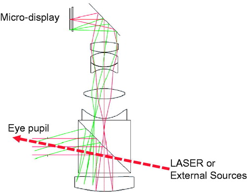
shows the light ray paths of the initial HMD design layout. The initial HMD was developed to utilize an optical system with the following specifications: a 20° diagonal half field angle, 0.8 cm pupil entrance diameter, and 1.7 cm effective focal length. The eye relief distance (located between an eye and the closet lens) was designed to be 1.5 cm for users such as doctors or surgeons [Citation13]. In the optical light paths of the initial HMD (), after going through the optical parts with a reflector and before a light ray is incident parallel at the stop surface, images from a surface can be focused on the inner part of an optical beam splitter.
Figure 1. Light ray paths of the initial HMD layout.
is an optical system layout with an image-size ratio adjustment to satisfy the system specifications. To design a small size HMD, the refracting optical powers of the cemented and convex lenses (the fourth to eighth surfaces in the initial HMD layout) were set to be equal to that of the cemented and the convex lens (seventh to eighth surfaces).
Figure 2. Light paths of the initial HMD with image size ratio adjustment, and (b) that of the HMD with its refracting surface powers of the convex lenses.
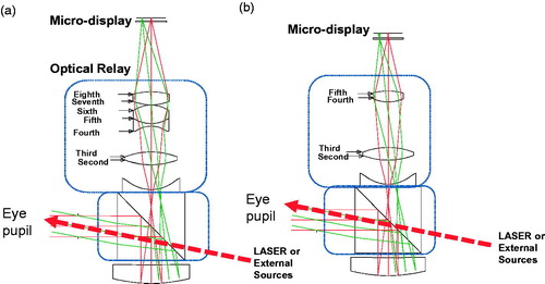
is an optical layout with the corresponding refracting surface powers of the convex lenses that can be replaced with a convex lens. To reduce optical distortion, an aspheric lens was replaced instead of the spherical lens, and to obtain zero distortion in the Seidel aberration, the fourth-order aspheric coefficient needs to be calculated. The distortion of the optical system in was calculated to be 78.32 × 10⁻²%. The second and third surfaces are spherical lens while the second surface was regarded as aspheric lens to obtain fourth-order aspheric coefficient.
The following equations describe the design parameters of the HMD design. First, EquationEq. (1)(1) describes the relationship between the focal length and resolution [Citation12]. The focal length determines the field of view (FOV) of the optical lens in the HMD. In order to obtain a high-resolution, we need to sacrifice the focal length of the optical lens [Citation13]. Therefore, there is a trade-off between them.
(1)
where S is the image source size, FL is focal length of the optical lens, and θr is the field angle.
EquationEq. (2)(2) shows a Seidel aberration coefficient SA*Vj for the optical distortion when considering the aspheric effect of the jth surface. The result of A4j is supposed to offset the resulting optical aberration.
(2)
where Cj, cj, and A4j are the conic coefficient, curvature, and fourth-order aspheric coefficient of the jth lens surface, respectively, and pj represents the optical axial ray paraxial image height at the jth lens surface.
refers to the optical chief ray paraxial image height at the jth surface, nj represents the jth surface index, n represents the image surface index.
EquationEqs. (2)(2) and Equation(3)
(3) are utilized to make the third order distortion for the entire surfaces of the zero system [Citation15].
(3)
where D represents the third order distortion for the entire surfaces in the optical systems and u represents the axial optical ray paraxial angle at the image surface.
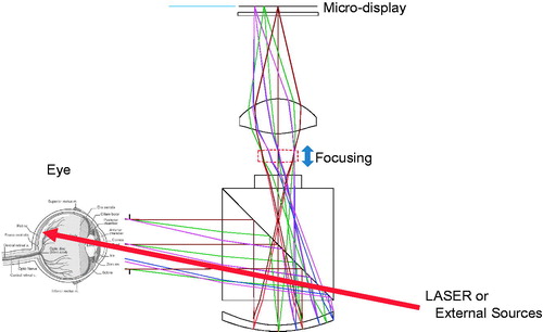
The calculated fourth-order aspheric coefficient of the second optical surface is −0.14, and the third-order distortion is supposed to be zero. Therefore, the fourth-order aspheric coefficient of the second surface is obtained. After the design optimization, the final HMD optical layout for image-guided applications is depicted in . The final HMD design was developed to be much smaller than the HMD design in .
Figure 3. Light paths of the final smallest size HMD.
Results and discussion
The optical design is the determined by the curvatures, thickness, and materials of each lens [Citation12]. Therefore, the collimated beams incident on the optical systems are supposed to be focused at a small spot on the image planes [Citation12].
The optical systems proposed in this paper play a role in the creation of a virtual object from a micro-display over a certain distance as shown in . At this point, a virtual object should be appropriately located according to the human vision. The micro-display position should be changed according to the changes in object distance. However, it is easier to implement an optical systems by moving a pieced of lens rather than by changing the micro-display positions. This function is called focusing, and the optical system is designed to be focused by moving a part of a pieced of lens as shown in . Therefore, the performances of the optical systems should be confirmed according to the movement of the focusing lens. However, if the optical system sizes becomes excessively large when worn on the face of a doctors, focusing ranges for imaging need to be determined such that no inconvenience is caused to the doctors and patients.
(4)
Figure 4. Optical layout for the virtual object of our designed HMD.
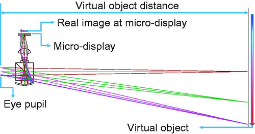
The diopter (D) is calculated as the reciprocal of the virtual object distance; +1 D indicates a virtual image distance of +1 m. In this paper, the designed optical systems can control the diopter with a range from +1 D to –4 D; −4 D indicates a virtual image distance of –0.25 m.
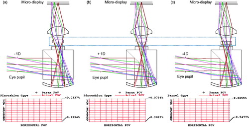
shows the optical layout and distortion grid of the optical systems. The principal performances of the HMD optical systems were evaluated by the optical resolutions and distortions [Citation12]. As shown in , the optical distortions between +1 D and −4 D is not significantly changed from +0.36% to −0.55% even though it is changed by the focusing lens. As shown in , the lattice shape is nearly maintained. To confirm the optical resolutions, it is necessary to check the f# of the optical systems. For the HMD optical system design, the entrance pupil diameter is typically designed to be large. However, the eye pupil sizes changes with a change in the brightness of surroundings. If HMD optical systems are utilized in the illumination environment of a surgery room, the pupil size is 3 − 4 mm in diameter [Citation16]. In this paper, the HMD optical systems must have a slightly brighter illumination environment than the general office of a surgeon to obtain the external sources and micro-display images because the diameter of the entrance pupil in the optical system should be 3 mm to evaluate optical resolutions. However, optical resolutions must be evaluated according to the eye pupil location because the eye pupil locations may change depending on the viewing area of the screen positions.
Figure 5. Optical layout and distortion grids of the final smallest size HMD at (a) −1 D, (b) + 1 D, and (c) + 4 D locations.
shows the results of the modulation transfer function (MTF) graphs when the entrance pupil is located in the center positions of the designed optical systems. The MTF graphs show the optical resolutions of the systems [Citation12]. These graphs show the calculated results when the entrance pupils are located at −1 D, +1 D, and −4 D positions from left to right. In other words, show the results of the defocused MTF when the eye pupils are located at center, +1 mm in the upward, right, downward and diagonal directions of the entrance pupil, respectively.
Figure 6. The defocused MTF graphs when the eye pupils are located in the center, + 1 mm in the upward, +1 mm in the right, +1 mm in the downward and diagonal directions of the entrance pupils.
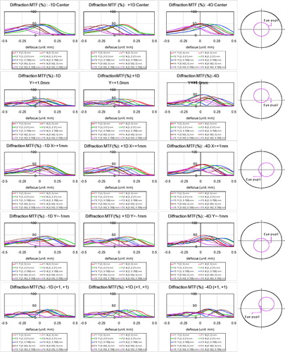
In , the x-axis represents the ±1.5 D location change of the micro-display in the optical systems. The solid line indicates the tangential MTF and the dotted line indicates the sagittal MTF. As shown in , the red color indicates the center MTF. However, the peripheral MTF and peak does not match due to the field curvature of the optical system. These field curvatures are not a significant issue because the HMD optical systems are focused on the eye lens. However, there is an issue in that the MTFs of the tangential and sagittal directions do not coincide with each other. However, users do not typically recognize such MTF differences within a ±0.5 D range [Citation17]. This can aid doctors to monitor the eye of patients with enhanced freedom because every patient has a unique pupil size. Therefore, we can conclude that the designed HMD optical systems have no significant issues in the performances of the optical distortions and resolutions for medical applications.
Conclusion
A new type of see-through HMD optical system was developed for concurrent image-guided treatment applications. In the HMD design, affordable plastic was selected to lighten the system with the smallest possible shapes to have acceptable optical performances. Moreover, a piece of lenses was moved from −4 D to +1 D for adjustment of focus when individual eyesight compensation is required. Therefore, a wide range focus adjustment in the designed HMD optical systems can aid doctors in obtaining images for treatment of patients with various pupil sizes. The system optical distortions and resolutions could be checked by distortion grids and MTF graphs. The designed adjustable focus see-through HMD optical systems showed that there are distortions of +0.36% in the +1 D location and −0.55% in the −4 D location and there is not a sensitive recognition of MTF differences within ±0.5 D locations. A low optical distortions also assists doctors in obtaining images with less dependence on image processing techniques. Therefore, we confirmed that our developed HMD optical systems performs well for image-guided treatment applications because it can provide the smallest possible shapes with an adjustable focusing function up to −4 D. This can be very useful for dual paths of imaging and treatment applications and it can also provide low optical distortions and high optical MTF resolutions.
Disclosure statement
The authors have no conflict of interests to disclose.
Additional information
Funding
References
- Mosenia A, Susmita S-K, Raghunathan A, et al. Wearable medical sensor-based system design: a survey. IEEE Trans Multi-Scale Comp Syst. 2017;3:124–138.
- Casson AJ, Yates DC, Smith SJ, et al. Wearable electroencephalography. IEEE Eng Med Biol Mag. 2010;29:44–56.
- Glaros CI, Fotiadis D. Wearable devices in healthcare. Intelligent Paradigms for Healthcare Enterprises. 2005. p. 59.
- Peden RG, Mercer R, Tatham AJ. The use of head-mounted display eyeglasses for teaching surgical skills: a prospective randomised study. Int J Surg. 2016;34:169–173.
- Quinlivan B, Butler JS, Beiser I, et al. Application of virtual reality head mounted display for investigation of movement: a novel effect of orientation of attention. J Neural Eng. 2016;13:056006.
- Spitzer MB. inventor; US Patents, assignee. Compact image display system for eyeglasses or other head-borne frames. United States Patent US 6,384,982. 2001 May 7.
- Rolland JP, Holloway RL, Fuchs H, editors. Comparison of optical and video see-through, head-mounted displays. Photonics Ind. Appl., Int. Soc. Opt. Photonics; 1995.
- Hua H, Javidi B. A 3D integral imaging optical see-through head-mounted display. Opt Express. 2014;22:13484–13491.
- Available from: https://en.wikipedia.org/wiki/Google_Glass
- Sugihara R, Iba Y, Tatsuta S. inventors; US Patents, assignee. Head-mounted image display device. United States Patent US 8,446,676, 2013 May 21.
- Sharma KK. Optics: principles and applications. Cambridge, MA: Academic Press; 2006.
- Bass M, van Stryland EW, Williams DR, et al. Handbook of optics. Vol. 2. New York: McGraw-Hill; 2001.
- Pedrotti FL, Pedrotti LS, Pedrotti LM, et al. Introduction to optics. Vol. 2. Englewood Cliffs (NJ): Prentice-Hall; 1993.
- Liang J, Grimm B, Goelz S, et al. Objective measurement of wave aberrations of the human eye with the use of a Hartmann–Shack wave-front sensor. J Opt Soc Am A. 1994;11:1949–1957.
- Jo JH, Ryu JM. The base and application of optical design with lens design program. Seoul (Korea): Chungmungak; 2013.
- Malacara-Hernández D, Malacara-Hernández Z. Handbook of optical design. Boca Raton (FL): CRC Press; 2016.
- Smith WJ. Modern lens design. Vol. 2. New York (NY): McGraw-Hill New York; 2005.