
Abstract
Surgical navigation has been shown to improve the accuracy of bone preparation and limb alignment in total knee arthroplasty (TKA). Previous work has shown the effectiveness of various types of navigation systems. Here, for the first time, we assessed the accuracy of a novel imageless semiautonomous handheld robotic sculpting system in performing bone resection and preparation in TKA using cadaveric specimens. In this study, we compared the planned and final implant placement in 18 cadaveric specimens undergoing TKA using the new tool. Eight surgeons carried out the procedures using three types of implant designs. A quantitative analysis was performed to determine the translational, angular, and rotational differences between the planned and achieved positions of the implants. The mean femoral flexion, varus/valgus, and rotational error was −2.0°, −0.1°, and −0.5°, respectively. The mean tibial posterior slope, and varus/valgus error was −0.2°, and −0.2°, respectively. We obtained higher flexion errors for the femoral implant when using cut-guides as compared to using a bur for cutting the bones. The image-free robotic sculpting tool achieved accurate implementation of the surgical plan with small errors in implant placement. Future studies will focus on determining how well the accurate implant placement translates into a clinical and functional benefit for the patient.
Introduction
Total knee arthroplasty (TKA) is considered to be a highly successful procedure, with implant survival rates between 81% and 92% at 15 years of follow-up [Citation1–4]. Accurate implant alignment is an important factor for a successful outcome [Citation5–8]. In general, coronal or frontal plane limb alignment within 2–3 degrees around a neutral alignment [Citation9–11] remains the gold standard. Some authors advocate small variances in varus/valgus alignment as more physiologic, but clinical study will be required to demonstrate no compromise in long term implant survival [Citation12].
In an effort to improve coronal alignment computer aided surgery (CAS) has been advocated with reported improvements in post-operative mechanical alignment [Citation7,Citation13,Citation14]. Even though CAS systems have led to reduced outliers in post-operative limb alignment, alignment beyond ±3 degrees is shown to range between 4 to 21% [Citation7,Citation15]. This is perhaps why clinical studies to date have not resulted in improved implant survival.
We are reporting on a novel optically-tracked surgeon-operated handheld robotic tool as part of a navigation system [Citation16–19]. Previously, this system was evaluated for its accuracy in unicondylar knee arthroplasty (UKA). Here, for the first time we present the navigation system that provides an image-free TKA procedure by relying on intraoperative anatomic collections, soft tissue laxity information, and multiple bone cutting control mechanisms. Here, we evaluate and report our investigation of the implant placement accuracy.
Materials and methods
In this study, 18 cadaveric specimens were used. Eight experienced TKA surgeons were involved in this evaluation, each operating on 2-3 specimens. Different implant design (Journey II, Genesis II, and Legion) and cruciate treatment (cruciate retaining, posterior stabilizing, and bicruciate stabilizing) options were used to avoid bias to any particular design.
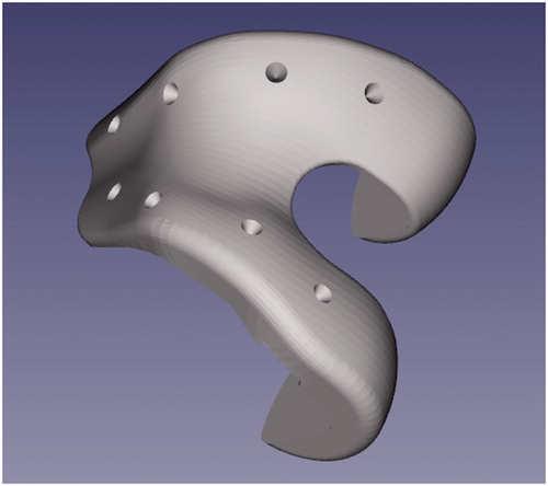
To document implant position, conical divots were drilled at known positions on all the implants. These divot positions were later used to measure the errors in the actual implant positions as compared to the planned implant positions.
Robotic navigation system
The Navio system (Smith & Nephew Inc.) was used to carry out the TKA procedure. This system is comprised of a mobile computer cart which includes a surgeon-controlled graphical user interface, a passive infrared camera tracking system (NDI Inc.), a handheld burring device with robotic control of the cutting function and a point probe which functions to calibrate the handpiece and to characterize patient anatomy (). The navigation system also includes reusable components such as TKA saw guides, leg tracking frames and other orthopedic hand tools.
Figure 1. Initial setup of bone trackers during a Navio TKA procedure. The bone arrays are fixed using bone screws on the femur and the tibia.
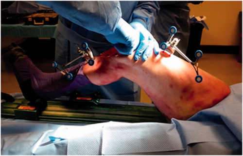
Figure 2. Soft tissue and ligament laxity characterization through full range of motion of the knee joint.
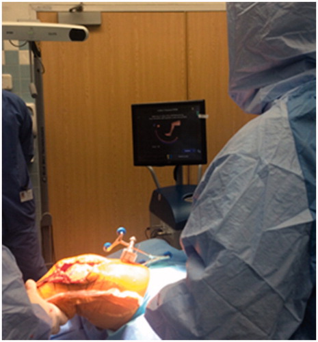
Figure 3. Use of the system point probe to map out the articular surface of the femur.
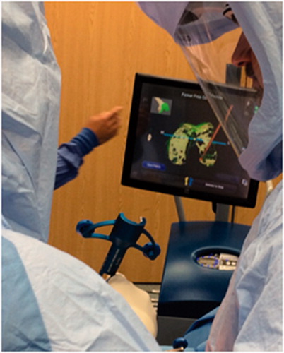
Figure 4. Use of optically-tracked bur to prepare the bone for placement of the cut-guide.
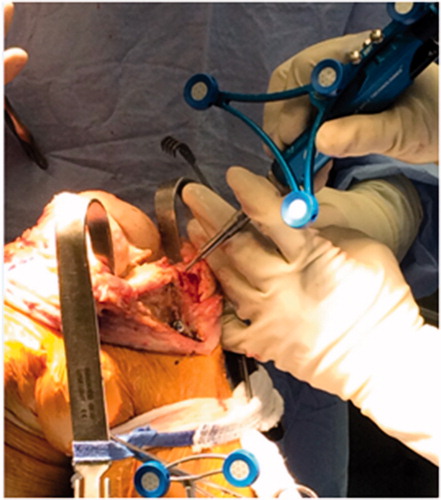
The Navio system functions in three phases – registration, planning and cutting. During the registration phase, the surgeon is guided by an interactive touchscreen display to define patient anatomy. Registration of patient anatomy involves bone and cartilage definition as well as characterization of ligament tension. In the planning phase, the surgeon uses the touchscreen to position a virtual implant model relative to the previously-defined anatomy and soft tissue characterization. In this phase, implant gap plots aid in balancing the joint and fine tune the postoperative soft tissue laxity. During the cutting phase, the system displays a color-coded virtual bone workpiece indicating bone material that is to be removed. An optically-tracked robotic handpiece, that houses a burring tool, is held by the surgeon to remove bone material. The handpiece can be configured in two control modes – exposure control, and speed control. In exposure control, the handpiece extends the spinning bur from a protective metallic sheath, known as a cut-guard. When the bur approaches bone material that is to be spared the handpiece retracts the bur into the cut-guard disallowing bone removal. In speed control, the system regulates the rotational velocity of the bur and terminates spinning (and bone removal) when the bur approaches bone material that is to be spared. Each control mode can be individually activated at any time during the cutting phase. Exposure control is used primarily in areas where access to the cut site is not limited. Speed control is used primarily in areas where use of a cut-guard limits the areas where bone cuts can be made, such as peg holes and posterior joint areas.
The Navio system allows two methods for bone removal. In the first method, the bone surface is prepared by using the optically-navigated bur to place saw cutting guides in a position consistent with the plan. The surgeon then uses an orthopedic oscillating saw to complete the bone cuts and place the implant trials. In the second method, the entirety of the bone cuts is carried out by using the optically-navigated bur. Following the placement of the implant trials, bone cement is prepared for final fixation of the implants.
Data collection
During the TKA procedure, the femoral and the tibial reference frames were rigidly attached using bicortical bone pins (). Thereafter, four conically divoted fiducial markers were drilled into the femur and the tibia. These fiducial markers were used to characterize the motion of the bone tracker arrays during the procedure. Any changes in the position of the bone tracker arrays introduce errors in the measurement of the final implant positions. This is because the implant accuracy measurement system relies on the bone tracker arrays to obtain the final implant positions. After the fiducial marker were drilled into the bone, the system guided the surgeon through the anatomy localization steps that include pivoting the leg about the hip, bending the leg at the knee joint, and collection of points by using the point collection probe. This allowed the system to estimate/collect the key landmarks points such as the hip center, femoral knee center, and other points needed to define the anatomic reference frames for the femur and the tibia. Furthermore, recording the unstressed and stressed range of motion of the knee joint aided in soft tissue and ligament laxity characterization (). The point collection probe was also used to map out the articular surfaces of the femur and the tibia (). Then, the surgeon used the collected data to plan the size and placement of the implants. Here, additional plots were presented to the surgeon in order to optimize the joint balancing and postoperative soft tissue laxity. Once the planning stage was completed, the system guided the surgeon through the bone cuts as described previously (). During implant trialling, a 3mm ball-point probe was used to collect the divot positions on the implant () in the intraoperative optical space (femoral/tibial reference frame). These divot positions were used to estimate the final implant positions in the intraoperative optical frames. This final position was then compared to the planned implant positions (transformed to the intraoperative optical frames) to obtain final implant placement error.
Figure 5. Cut-guide placement based on intra-op plan after the bone cuts.
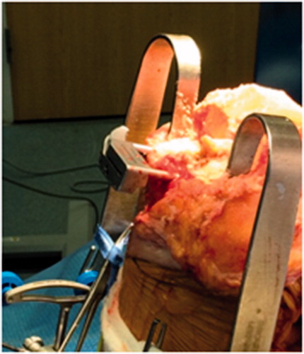
Figure 6. System confirmation of the saw blade cut planes before final bone cuts.
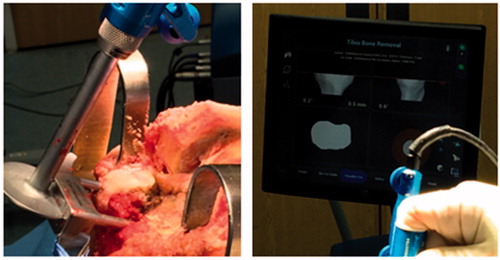
Figure 7. Use of optically navigated hand-held bur to carry out the planned bone cuts.
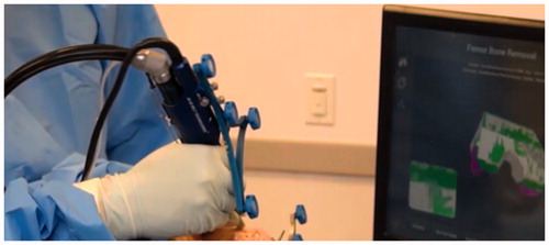
Figure 8. 3D model of a divoted implant.
Results
The results of the study are presented in . Graphical presentation of some of the cases is given in . In our study, in 4 out of the 18 cadavers the bur was used to make the final bone cuts (presented as “Bur error” in ). In the remaining 14 cases, the cut-guide was used to make the final bone cuts. The “total error” presents the implant placement error for all the cases. The Navio robotic system does not constrain the medio-lateral position of the femoral implant which is selected by the surgeon. For the tibial implants, the medio-lateral and antero-posterior positions as well as the rotation of the implant is left to the discretion of the surgeon. Thus, these entries are shown as “*” in . We observe from that all the absolute mean cut-guide errors are less than 1 mm or degrees except the flexion error for the femoral implant. The standard deviation for cut-guide errors ranges from 0.6 to 2.4 mm or degrees for the femoral and tibial implants. The absolute mean bur errors are less than or equal to 1 mm or degrees for the femoral and tibial implants. The standard deviation of the bur errors are less than 1 mm or degrees for the femoral and tibial implants.
Figure 9. Overlay of planned (yellow) and actual (white) implant positions for 8 cases.
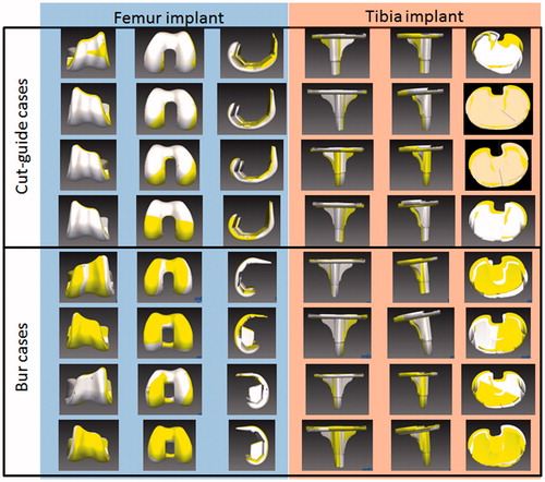
Table 1. Overall, burring and cutguide-based implant placement error.
Discussion
Computer assisted surgery (CAS) applications for TKA procedures have been developed to improve post-operative leg alignment. Mason et al. carried out a meta-analysis of CAS TKA and found that mechanical axis malalignment occurred in 9% of CAS TKA against 31% in case of traditional TKA [Citation20]. A previous study found that many early TKA revisions were due to instability and leg malalignment, both of which may be related to component malalignment [Citation21]. Two meta studies found that CAS TKAs provide significant improvement in the component orientation [Citation22,Citation23]. Baier et. al used an image-free CAS system and reported femoral varus/valgus alignment accuracy of 0.3 ± 1.5°, and flexion alignment accuracy of 3.0 ± 2.1° [Citation24]. They obtained tibial varus/valgus alignment error of 0.0 ± 0.6° and slope alignment error of 5.4 ± 1.2°. Garvin et al. presented results from a navigated TKA saw blade [Citation25]. They reported implant alignment varus/valgus errors of −0.55 ± 1.1° and slope errors of 1.6 ± 1.4°. We believe the novel system reported here represents a refinement and improvement in optical tracking for TKA surgery.
Previously, the navigation system presented in this paper has been evaluated for its accuracy in UKA [Citation16–19]. Here, for the first time, we used an optically tracked hand-held robotic tool as part of a TKA navigation system. This work focused on the implant placement accuracy of the system. We found that the overall femur varus/valgus mean orientation error was −0.1° with a standard deviation of 0.9°. Similar results were obtained for the tibial varus/valgus error (−0.2 ± 0.9°). The posterior error slope error for the tibial implant was −0.2 ± 1.3°. The femoral implant rotation error was also similar −0.5 ± 1.2°. However, the femoral implant flexion/extension error was −2.0 ± 2.2°. Further analysis revealed that the femoral implant flexion/extension error was low when using the bur −1.0 ± 0.5° but higher when using the cut guides (−2.2 ± 2.4°). This was due to overcuts of the femur bone during the posterior cuts.
Our study suffered from a few limitations. The cadaver specimens were unequally distributed between cases using cut guides and those using burs. There was a large variation in the type of implants used and the implant sub-design. However, here we evaluated the accuracy of the bone cuts and the type of implant or implant sub-design used did not matter in this evaluation. Eight surgeons were involved in the study which increases the number of variables in the study.
For the first time, we have presented implant placement accuracy of a handheld robotic TKA navigation system. We did find higher flexion errors for the femoral implant when using cut-guides that could be mitigated by combining use of cut guides and a bur for cutting the bones. Our results also show that in all the cases the coronal orientation error of the femur and tibia implants was within 2° of neutral [Citation15,Citation26,Citation27]. However, this study consisted of only 18 cadaver specimens and more studies are needed to obtain statistically significant results.
Disclosure statement
Michael Casper, Riddhit Mitra, Rahul Khare, and Branislav Jaramaz are paid employees of Smith & Nephew Inc. Brian Hamlin, Brian McGinley, David Mayman, Jeff Headrick, Kenneth Urish, Mark Gittins, Stephen Incavo, and Vivek Neginhal are paid consultants for Smith & Nephew Inc.
References
- Roberts VI, Esler CNA, Harper WM. A 15-year follow-up study of 4606 primary total knee replacements. J Bone Joint Surg Br. 2007;89(11):1452–1456.
- Gøthesen O, Espehaug B, Havelin L, et al. Survival rates and causes of revision in cemented primary total knee replacement: a report from the Norwegian Arthroplasty Register 1994–2009. Bone Joint J. 2013;95–B(5):636–642.
- Rand JA, Ilstrup DM. Survivorship analysis of total knee arthroplasty. Cumulative rates of survival of 9200 total knee arthroplasties. J Bone Joint Surg Am. 1991;73(3):397.
- Parratte S, Pagnano M, Trousdale RT, et al. Effect of postoperative mechanical axis alignment on the fifteen-year survival of modern, cemented total knee replacements. J Bone Joint Surg Am. 2010;92:2143–2149.
- Figgie HE, Goldberg VM, Figgie MP, et al. The effect of alignment of the implant on fractures of the patella after condylar total knee arthroplasty. J Bone Joint Surg Am. 1989;71(7):1031–1039.
- Nizard R. Computer assisted surgery for total knee arthroplasty. Acta Orthop Belg. 2002;68(3):215–230.
- Bäthis H, Perlick L, Tingart M, et al. Alignment in total knee arthroplasty. A comparison of computer-assisted surgery with the conventional technique. J Bone Joint Surg Br. 2004;86(5):682–687.
- Lotke PA, Ecker ML. Influence of positioning of prosthesis in total knee replacement. J Bone Joint Surg Am. 1977;59(1):77–79.
- Ritter MA, Faris PM, Keating EM, et al. Postoperative alignment of total knee replacement. Its effect on survival. Clin Orthop. 1994;299:153–156.
- Jeffery RS, Morris RW, Denham RA. Coronal alignment after total knee replacement. Bone Joint J. 1991;73–B(5):709–714.
- Oswald MH, Jakob RP, Schneider E, et al. Radiological analysis of normal axial alignment of femur and tibia in view of total knee arthroplasty. J Arthroplasty. 1993;8(4):419–426.
- Stucinskas J, Robertsson O, Sirka A, et al. Moderate varus/valgus malalignment after total knee arthroplasty has little effect on knee function or muscle strength. Acta Orthop. 2015;86(6):728–733.
- Chauhan SK, Clark GW, Lloyd S, et al. Computer-assisted total knee replacement. Bone Joint J. 2004;86–B(6):818–823.
- Haaker RG, Stockheim M, Kamp M, et al. Computer-assisted navigation increases precision of component placement in total knee arthroplasty. Clin Orthop. 2005;433:152–159.
- Jenny JY and Boeri C. Computer-assisted implantation of total knee prostheses: a case-control comparative study with classical instrumentation. Comput. Aided Surg Off J Int Soc Comput Aided Surg. 2001;6(4):217–220.
- Lonner JH and Moretti VM. The evolution of image-free robotic assistance in unicompartmental knee arthroplasty. Am J Orthop Belle Mead NJ. 2016;45(4):249–254.
- Lonner JH, Smith JR, Picard F, et al. High degree of accuracy of a novel image-free handheld robot for unicondylar knee arthroplasty in a cadaveric study. Clin Orthop. 2015;473(1):206–212.
- Lonner JH. Robotically assisted unicompartmental knee arthroplasty with a handheld image-free sculpting tool. Oper Tech Orthop. 2015;25(2):104–113
- Smith JR, Riches PE, Rowe PJ. Accuracy of a freehand sculpting tool for unicondylar knee replacement. Int J Med Robot Comput Assist Surg MRCAS. 2014;10(2):162–169.
- Mason JB, Fehring TK, Estok R, et al. Meta-analysis of alignment outcomes in computer-assisted total knee arthroplasty surgery. J Arthroplasty, 2007;22(8):1097–1106.
- Sharkey PF, Hozack WJ, Rothman RH, Shastri S, and Jacoby SM. Insall Award paper. Why are total knee arthroplasties failing today?. Clin Orthop. 2002;404:7–13.
- Cheng T, Zhao S, Peng X, and Zhang X. Does computer-assisted surgery improve postoperative leg alignment and implant positioning following total knee arthroplasty? A meta-analysis of randomized controlled trials? Knee Surg Sports Traumatol Arthrosc Off J ESSKA. 2012;20(7):1307–1322.
- Brin YS, Nikolaou VS, Joseph L, Zukor DJ, and Antoniou J. Imageless computer assisted versus conventional total knee replacement. A Bayesian meta-analysis of 23 comparative studies. Int Orthop. 2011;35(3):331–339.
- Baier C Maderbacher G, Springorum HR, et al. No difference in accuracy between pinless and conventional computer-assisted surgery in total knee arthroplasty. Knee Surg Sports Traumatol Arthrosc Off J ESSKA. 2014;22(8):1819–1826.
- Garvin KL, Barrera A, Mahoney CR, et al. Total Knee Arthroplasty With a Computer-navigated Saw: A Pilot Study. Clin Orthop. 2013;471(1):155–161.
- Decking R, Markmann Y, Fuchs J, et al. Leg axis after computer-navigated total knee arthroplasty: a prospective randomized trial comparing computer-navigated and manual implantation. J Arthroplasty. 2005;20(3):282–288.
- Matsumoto T, Tsumura N, Kurosaka M, et al. Prosthetic alignment and sizing in computer-assisted total knee arthroplasty. Int Orthop. 2004;28(5):282–285.