
Abstract
It is technically demanding and requires rich experience to insert the translaminar facet screw(TFS) via the paramedian mini-incision approach. It seems that it is easy to place the TFS using computer-assisted design and rapid prototyping(RP) techniques. However, the accuracy and safety of these techniques is still unknown. The aim of this study is to assess the accuracy and safety of translaminar facet screw placement in multilevel unilateral transforaminal lumbar interbody fusion using a rapid prototyping drill guide template system. A patient-matched rapid prototyping translaminar facet screw guide was examined in fourteen cadaveric lumbar spine specimens. A three-dimensional (3D) preoperative screw trajectory was constructed using spinal computed tomography scans, from which individualized guides were developed for the placement of translaminar facet screws. Following bone tunnel establishment, the 3D positioning of the entry point and trajectory of the screws was compared to the preoperative plan as found in the Mimics software.Among 60 trajectories eligible for assessment, no cases of clinically significant laminar perforation were found. The mean deviation between the planned and the actual starting points on spinous process was 1.22 mm. The mean tail and submergence angle deviation was found to be 0.68°and 1.46°, respectively. Among all the deviations, none were found to have any statistical significance. These results indicate that translaminar facet screw placement using the guide system is both accurate and safe.
Introduction
Since its first use by Harms and Rolinger in 1982, transforaminal lumbar interbody fusion (TLIF) has been a popular and well-established surgical intervention for patients suffering from lumbar degenerative diseases [Citation1]. The bilateral pedicle screws (BPS) fixation is considered the “gold standard” of treatment because it can provide rigid fixation, which helps achieve a solid arthrodesis and increase rates of fusion. However, the disadvantages of the procedure are obvious, such as long skin incisions, bilateral paravertebral muscle atrophy, device related osteoporosis, absorption of grafted bone and degeneration to adjacent segments [Citation2–4]. Accordingly, several modified techniques have been assessed by finite element analysis and biomechanical tests, for example, unilateral pedicle screw (UPS), UPS with contralateral translaminar facet joint screw (UPS + TFS) and etc. The results show that the stability of UPS + TFS is similar to that of BPS for both 1-level and 2-level lumbar spinal disorders [Citation5–7]. Moreover, some recent clinical studies also indicate TLIF using UPS + TFS by paramedian mini-incision is a safe, feasible and effective method to treat one or two segment lumbar degenerative disorders [Citation8,Citation9]. Our own understanding suggests that to insert the translaminar facet screw via the paramedian mini-incision approach is technically demanding and requires rich experience. If the TFS is too deep, dural sac and contralateral nerve roots may be damaged, contrarily, if the TFS is too superficial, there may not be enough strength to fix the contra-facet joint. We seek to place the TFS properly and easily using computer-assisted design and rapid prototyping(RP) techniques. Therefore, the aim of this study is to assess the accuracy and safety of the RP drill template in the placement of contralateral translaminar facet screws in the cadaveric lumbar spine.
Methods
Specimen preparation
Fourteen cadaveric human lumbar spines were harvested from human donors (age range 42–71 years; 6 male, 8 female) at the Human Anatomy Department of Fudan University. A total of sixty human lumbar segments were harvested, out of which there are 2T12/L1, 14 L1/2, 14 L2/3, 14 L3/4, 14 L4/5, and 2 L5S1 respectively. Patient medical records were checked to exclude specimens with traumatic, neoplastic, or metabolic disorders history.
The specimens were frozen immediately after harvesting and stored at −80 °C. They were thawed at room temperature (20 °C) overnight for preparation and testing. After thawing, the superficial musculature was then removed. However, all intervertebral ligamentous structures, the capsules of the facet joints and annulus were preserved.
Trajectory design
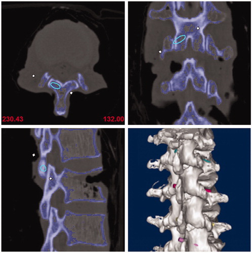
All specimens received a three-dimensional CT scan (Somatom, Siemens) and the collected CT data was stored in dicom format. Next, the data was imported into Mimics Innovation suite V17.0, which allowed the image mask and lumbar 3D model to be built. This also allowed the best virtue trajectory for the translaminar facet screw to be made. Given the 4.5 mm diameter of the translaminar facet screw, the initial trajectory (trajectory 1) requirements were determined accordingly. The starting point was determined as the midpoint at the base of spinous processes, the end point was determined as the midpoint at the articular surface of the contralateral facet joint. Additionally, the center of the trajectory was located in the center of the cancellous bone of lamina, and no overlapping between the edge of the trajectory and the ventral or the dorsal lamina cortex. When the lamina was too thin compared to the diameter of the screw trajectory, breaking the dorsal cortex was found to be a better option than breaking the ventral cortex. Indeed, to correctly determine the best position of the trajectory, the starting and ending point sometimes needed to be fine-tuned. Finally, its central axis was drawn and the diameter of the trajectory was narrowed to 3.5 mm(trajectory 2) ().
Figure 1. Screw trajectories were designed on 3D lumbar models.
Guide printing and actual trajectory establishment
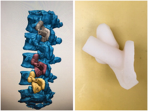
After screw trajectories were confirmed, screw guides were designed, which included matching, connecting and channel parts. The matching part was only matched to the region on one sole vertebral body without crossing the vertebral joint (). According to guide design diagrams, actual guides were printed with a rapid prototyping technique.
Figure 2. Translaminar facet joint screw guide was designed including matching, connecting and channel parts.
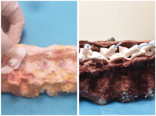
In relation to screw guides, actual screw trajectories (trajectory 3) were created on specimens using a 3.2 mm drill, and a 3.2 mm polylactic acid(PLA) rod was inserted into each bone tunnel ().
Figure 3. Actual screw trajectories were created on specimens with a 3.2 mm drill and 3.2 mm polylactic acid rods were inserted in to bone tunnels.
Evaluation of accuracy and safety
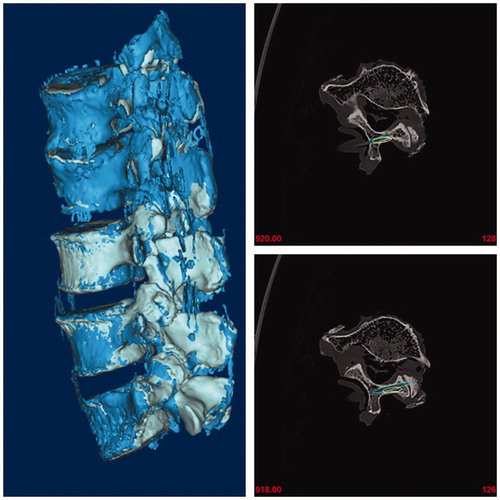
After bone tunnels were established, another 3-dimensional CT scan for specimens with PLA rods was performed and the results were imported into the software, and postoperative 3D lumbar models were generated. To ensure that two trajectories were comparable and in line with clinical applications, the central axis of trajectory 3 was also drawn and the diameter was extended to 4.5 mm based on this axis (trajectory 4). Finally, post-operative and pre-operative 3D lumbar models with actual and planed trajectories were coincided in the same coordinate system. ()
Figure 4. Post-operative and pre-operative 3D lumbar models with actual and planed trajectories were coincided in the same coordinate system.
The absolute distance of the starting point, the deviation of the tail and submergence angles between trajectory 1 and trajectory 4 were measured. The distance and direction deviation between trajectory 1 and trajectory 4 was used to evaluate the accuracy of the TFS guide. Additionally, the trend to destroy the cortex by trajectory 4 was analyzed to evaluate safety. Finally, thickness of the vertebral laminae was also measured.
Statistics
The data were presented as mean ± SD (standard deviation). SPSS 21.0 was used for all statistical analysis of the data. A comparison of the individual treatment was conducted using a Student's t test. Differences were considered statistically significant for (p < .05).
Results
Thickness of spinal vertebral laminae
In this study, thickness of vertebral laminae was classified as three grades: >4.5 mm as grade A, 3.5–4.5 mm as grade B and <3.5 mm as grade C. Among all 60 laminae, 22 were classified as grade A, 26 as grade B and 12 as grade C. The L3 lamina was found to be the narrowest, with 4 in grade B and 10 in grade C. the L1 and L2 lamina were the widest, and 18 of the 28 laminae were found to be grade A.
Association between screw trajectory and lamina cortex
The safety of the screw trajectories was assessed based on the positional relationship between trajectories and the ventral cortex of laminae, and was classified as three grades: Grade 0: screw trajectory margin has no contact with the ventral cortex of laminae, Grade 1: screw trajectory has contact with the ventral cortex and Grade 2: screw trajectory intruding the ventral cortex. In our study, 10 trajectories was determined as grade 0, and 50 trajectories as grade 1. For 4.5 mm diameter screws, no trajectory was found to break through the ventral cortex. All 60 trajectories of the 4.5 mm screws were found to break through the articular face of the contralateral facet joint. Therefore, the TFS guides were found to be 100% safe.
Accuracy of TFS guide
The absolute distance of the starting point between two trajectories was measured. The positive value represented cephalad migration and negative value represented caudal migration (). Compared with trajectory 1, the mean distance of the starting point of trajectory 4 was 0.15 ± 1.14 mm (2.18 to −1.93 mm). The starting points between actual and planned trajectories were found to have no significant differences. The mean tail and submergence angles of trajectory 1 were 35.32 ± 5.82°and 24.01 ± 6.28°, respectively. However, the mean tail and submergence angles of trajectory 4 were 36.01 ± 5.37°and 24.97 ± 6.63°, respectively. No significant differences between the two trajectories about the tail and submergence angles were found. Therefore, the accuracy of the TLFS guides was also 100%.
Table 1. The deviation about starting point, tail angle and submergence angle between designed and actual trajectories.
Discussion
Since reported in 1982 [Citation1], BPS fixation has become a standard method in transforaminal lumbar interbody fusion. Although BPS fixation may provide sufficient stability, it requires strip bilateral paraspinal muscles and increases soft tissue injury. UPS fixation may reduce the operation wound. However, its stability was found to be decreased, especially in rotation and flexion. To increase the stability of UPS fixation and to decrease the operation wound of BPS fixation, UPS plus contralateral facet joint screw fixation (UPS + TFS) has been performed by some authors. This is a proven safe and effective treatment in treating lumbar degenerative diseases.
Although UPS + TFS has become more and more popular in TLIF, it still remains a challenge for surgeons to insert TFS accurately and safely. Firstly, the insertion of TFS is guided by means of a C-arm machine at present, which increases the radiation for both patients and doctors. Secondly, correct and optimal TFS placement depends on the surgeon’s experience and ultimately mood on the day of surgery. As such, a large learning curve is required to successfully conduct this form of surgery. Thirdly, the thickness of laminae is also a factor that affects the safety of screws. In our study, only 22 of 60 lamina were found to be thicker than 4.5 mm, with 18 of the 22 focused on L1 and L2. As such, when 4.5 mm screws were inserted, either of the ventral and dorsal cortex in most vertebra would likely be broken. This not only increases the probability of spinal cord and nerve injury, but also increases the difficulty of safe screw placement. Given the above disadvantages, therefore, the application of TFS is limited, and improving the safety and simplicity of TFS insertion is a matter of urgency.
A screw guide is widely used in the internal fixation of extremity fractures, as it may fix the direction of pins or drills. However, this guide was found to be limited because the direction of screw in the contralateral facet joint is invisible and depends on surgeon’s experience and mood during the operation. As such, the accuracy of the guide was greatly reduced during TFS operations. Therefore, we are committed to the invention of an individual guide that controls the screw direction during TFS operations.
RP technology is widely used in the field of orthopedics, and may quickly transform digital design into a physical entity. In recent times, a number of spinal screw guides have been produced using RP technology [Citation10–12]. However, to our knowledge and understanding, only a few have achieved desired effects. It has been reported that 26% of all pedicle screws were inserted inaccurately, with the length of 14% of screws too dissimilar in design for successful use of the multi segmental lumbosacral screw guide designed by Merc [Citation10]. In this study, we used RP technology to make our own TFS guide. It was predesigned using 3-dimensional CT scan data. Our guide consists of three parts, including matching, connecting and channel. The matching part was designed to match the upper articular process, chevron crest, lamina and the base of spinous process at the same side of the incision on the single vertebra, without crossing the vertebral joint. The channel part was designed and painted using a 3-dimensional spine model according to TFS trajectory. The connection was found between these two parts.
In our initial vision, it was thought that once the matching part was matched with the vertebra, the position of the channel part was also determined and need not be controlled by the surgeon during the procedure. As such, the TFS could be inserted according to the direction designed beforehand, and its accuracy could be increased in principle. To evaluate whether the accuracy and safety of the TFS guide could achieve the expected results, the actual bone channel made with the guide was compared with the virtue trajectory designed in each vertebra in the model used in our study, which included the starting point, the tail angle and the submergence angle. In our study, the mean difference between two trajectories about the starting point, tail angle and submergence angle was found to be only 0.15 ± 1.14 mm, 0.68 ± 3.35°and 0.96 ± 2.68°, respectively. There are no significance differences in any of the three aspects. This means that the actual bone channel made by means of the RP guide was consistent with the path of the designed trajectory. The different accuracy between our result and Merc’s result may be explained by the differences present in the matching part. In Merc’s study, the regions matched with the matching part of the guide were found across the facet joint. As such, when the position of the body during operation was inconsistent with the preoperative CT scan, the guide would fail to fit the spine completely. This may be the reason why so many screws were not inserted accurately. Matching regions were changed to limit a single vertebra in our guide to reduce the influence of spinal activity. Given this improvement, screws could be placed almost entirely in the direction of the guide.
Moreover, the accuracy of TFS is also a guarantee of safe implantation. With the help of this guide, no trajectories broke through the ventral cortex in this study. An intact ventral cortex means that the spinal cord and nerves are secured. As such, it is safe to insert the TFS using this guide. Given the accuracy and safety of the guide, it does not require such a large learning curve to insert TFS.
In our study, the diameter of the trajectory was changed twice on models using the software during the whole experimental procedure. At the design stage, the diameter was narrowed from 4.5 mm to 3.5 mm. As the 4.5 mm screw only required a 3.2 mm drill in clinical operations, and to limit the sway of the drill in the guide, the inner diameter of the guide should theoretically be the same as that of the drill. However if the diameter of the guide was too close to 3.2 mm, it was thought that friction between the drill and channel would be produced. This friction force would cause the displacement of the guide on the vertebra,thereby affecting the accuracy of drill insertion. Accordingly, the diameter of the channel chosen by us for the guide was 3.5 mm. Given this 0.3 mm gap between guides and drills, the drills were not only allowed to smoothly enter and exit through guides, but also prevented from swaying excessively. Indeed, the closer the diameter is to 3.2 mm, the less the drill shake in the channel and the more accurate the TFS becomes. As such, the fact that the smaller channel diameter for the guide was not chosen in this study may have been a small design flaw. Therefore, the minimum diameter of the channel that does not produce friction with the drill needs to be studied in future researches.
After actual bone trajectories in the laminae were scanned by CT and imported into the software, the diameter was extended from 3.2 mm to 4.5 mm, because the latter is common used during TFS. As such, it was more accurate to evaluate the safety of the screw insertion when the diameter of trajectory was similar to that of clinically used screws. Therefore, these two changes in diameter ensured consistency between experimental procedure and clinical application.
Conclusion
Screw trajectories created using the guide of rapid prototyping TFS guide template system were found to be consistent with those designed on models beforehand and were not found breaking through the ventral cortex. We believe once the rapid prototyping TFS guide is used in clinical operations, the accuracy and safety of TFS should increase as technical difficulty, operation time and radiation decrease.
Disclosure statement
No potential conflict of interest was reported by the authors.
Additional information
Funding
References
- Harms J, Rolinger H. A one-stager procedure in operative treatment of spondylolistheses: dorsal traction-reposition and anterior fusion (author’s transl). Z Orthop Ihre Grenzgeb. 1982;120:343–347.
- McAfee PC, Farey ID, Sutterlin CE, et al. 1989 Volvo Award in basic science. Device-related osteoporosis with spinal instrumentation. Spine (Phila Pa 1976). 1989;14 (9):919–926.
- McAfee PC, Farey ID, Sutterlin CE, et al. The effect of spinal implant rigidity on vertebral bone density. A canine model. Spine (Phila Pa 1976). 1991;16(6suppl):S190–S197.
- Park P, Garton HJ, Gala VC, et al. Adjacent segment disease after lumbar or lumbosacral fusion: review of the literature. Spine (Phila Pa 1976). 2004;29(17):1938–1944.
- Chen SH, Lin SC, Tsai WC, et al. Biomechanical comparison of unilateral and bilateral pedicle screws fixation for transforaminal lumbar interbody fusion after decompressive surgery: a finite element analysis. BMC Musculoskelet Disord. 2012;13:72.
- Gong Z, Chen Z, Feng Z, et al. Finite element analysis of 3 posterior fixation techniques in the lumbar spine. Orthopedics. 2014;37(5):e441–e448.
- Liu F, Feng Z, Liu T, et al. A biomechanical comparison of 3 different posterior fixation techniques for 2-level lumbar spinal disorders. J Neurosurg Spine. 2016;24(3):375–380.
- Cao Y, Chen Z, Jiang C, et al. The combined use of unilateral pedicle screw and contralateral facet joint screw fixation in transforaminal lumbar interbody fusion. Eur Spine J. 2015;24(11):2607–2613.
- Liu F, Cao Y, Feng Z, et al. Comparison of three different posterior fixation techniques in transforaminal lumbar interbody fusion for two-level lumbar degenerative diseases: at a mean follow up time of 46 months. Clin Neurol Neurosurg. 2016;141:1–6.
- Merc M, Drstvensek I, Vogrin M, et al. Error rate of multi-level rapid prototyping trajectories for pedicle screw placement in lumbar and sacral spine. Chin J Traumatol. 2014;17(5):261–266.
- Sugawara T, Higashiyama N, Kaneyama S, et al. Multistep pedicle screw insertion procedure with patient-specific lamina fit-and-lock templates for the thoracic spine. J Neurosurg Spine. 2013;19(2):185–190.
- Kaneyama S, Sugawara T, Sumi M, et al. A novel screw guiding method with a screw guide template system for posterior C-2 fixation. J Neurosurg Spine. 2014;21(2):231–238.