
 ?Mathematical formulae have been encoded as MathML and are displayed in this HTML version using MathJax in order to improve their display. Uncheck the box to turn MathJax off. This feature requires Javascript. Click on a formula to zoom.
Abstract
When the spinal surgery robot assists the surgeon perform the surgery, the patient is prone on the operating table. However, due to the force of the surgical instruments on the spine, there is a corresponding deformation in the surgical field, which affects the accuracy of the operation. In order to improve the accuracy and safety of the operation, this paper reconstructs the three-dimensional model of the lumbar spine which includes the vertebral body and the intervertebral disc based on the CT scan data, and then the lumbar spine is analyzed by the finite element method. The mathematical model of the relationship between force and displacement is established by using response surface methodology based on the simulation results. After that, the position control system is constructed based on the mathematical model. Through the simulation of the control system, the trajectory curve of the end of the manipulator is compared and the validity of the mathematical model is verified.
I.Introduction
With the rapid social and economic development and the gradual acceleration of the pace of life, people often need a long time of high-intensity work, while ignoring the daily exercise and protection of the spine. Long sitting posture can lead to long-term flexion or other fixed position of the spine, resulting in spinal diseases. The operation process of spinal surgery is generally simple and fixed, but due to the surgical site is the spine, the operation is very risky. The pedicle screw fixation is one of the most common operations in spinal surgery. And the most important process of this operation is to use the bone drill to drill the nail path, which has requirements for the entry point, angle and depth. The surgeons can quickly and accurately find the surgical operating position with the help of a spinal surgery robot which can operate under the guidance of a medical image, but when the surgical instrument interacts with the spine, the spine can deform which in turn can affect the actual position of the planned trajectory before surgery.
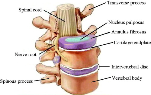
The lumbar vertebrae are mainly composed of vertebral body and intervertebral discs. And as shown in , vertebral body mainly includes transverse processes, spinous processes, upper/lower articular process, vertebral foramen, lamina and papillae. The intervertebral disc is composed of the upper and lower endplates, the nucleus pulposus and the annulus fibrosus [Citation1]. The upper and lower endplates are located at the bottom and top of the annulus fibrosus and they are the cartilage structure, which can be considered as elastic body. The nucleus pulposus is located in the middle of the annulus fibrosus, which is the incompressible fluid structure and belongs to the viscoelastic body and can withstand greater pressure. The annulus fibrosus which belongs to the super elastic body, surrounds the nucleus pulposus and connects the adjacent vertebrae through the upper and lower endplates [Citation2,Citation3]. The vertebral body consists of cortical bone and cancellous bone and the material parameters of the two parts are different [Citation4].
Figure 1. Structures of vertebral body and intervertebral disk.
In order to obtain the relationship between the force and the deformation of the lumbar spine under the action of surgical instruments, the researchers mainly focus on the biomechanical modeling of the intervertebral disc. A large number of biomechanical tests were performed on the compression, stretching, bending, torsion, composite loading and fatigue of the intervertebral discs by scholars such as Virgin, Brown, Farfan and Markolf. The corresponding mechanical properties of the intervertebral disc were measured and the results showed that the intervertebral discs injury were mainly caused by the composite load [Citation5–10]. Viviani first applied the finite element method to the field of scoliosis, which was used to guide the surgical correction and optimize the correction scheme [Citation11]. Sonnerup proposed a continuous disc model and analyzed the stress distribution in the intervertebral disc which used the linear elastic theory. However, the deficiency of the model was that it did not consider the effects of viscoelasticity and ligaments [Citation12]. Belytschko first established a two-dimensional linear finite element model of the intervertebral disc [Citation13], subsequently, Liu established a three-dimensional linear finite element model of anterior lumbar spine [Citation14]. Furlony established a finite element model of the intervertebral disc and fitted the results of the experiment. Although the model considered viscoelasticity, the nucleus pulposus and annulus fibrosus in the disc are treated as the same material [Citation15]. T. Zander established the nonlinear finite element model of the L1-L5 segment of the spine which took into account the effect of the stress distribution on the muscles [Citation16]. Rohlmann established the finite element model of lumbar spine of the human body and calculated the stress distribution in flexion and extension respectively, and compared with the experimental data to prove the validity of the simulation data [Citation17].
The most dangerous part of the pedicle screw fixation is drilling the nail path. Since the spinal cord, nerves and blood vessels are distributed in the vertebral hole, the spinal cord and nerves may be injured once inside the nail tract. In order to ensure the safety and reliability of the drilling process and achieve the best surgical results, it is imperative to accurately control the angle and depth of the drilling nail path. So this paper proposes the method to improve the safety and stability of the pedicle screw fixation.
In this paper, a mathematical modeling method is proposed for the deformation of the lumbar spine by the response surface methodology which is based on the finite element simulation. The method analyses the deformation of the lumbar spine when the surgical instrument acts on it, accurately quantifies the deformity of the lumbar spine, compensates the robot for spine surgery better and improves the accuracy and safety of the operation.
This paper is organized as follows. The section II reconstructs the three-dimensional model of the spine and performs finite element analysis on it. The section III gets the mathematical model of the deformation of the spine which based on the results of the finite element analysis and the method of using the response surface. The section IV designs and simulates the compensation control system which based on position control. The following discussion and conclusion are given in Section V.
II.Establishment of finite element model
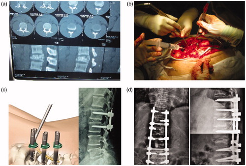
During lumbar surgery, the patient is prone on the operating table. The doctor cuts the back of the patient with the scalpel to expose the area of operation and then operates on the spine. As shown in , it is the surgical procedure of pedicle screw fixation.
Figure 2. Surgical procedure of pedicle screw fixation.
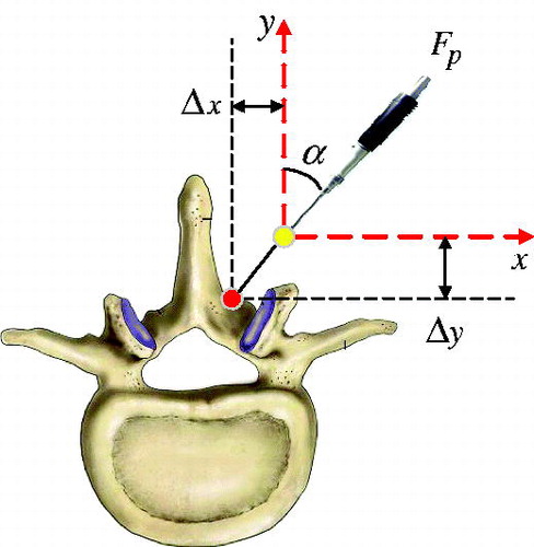
When the surgical instrument acts on the spine, the spine can produce deformation. As shown in , it is the diagram of the interaction between the vertebral body and surgical instrument.
Figure 3. Diagram of the interaction between the vertebral body and surgical instrument.
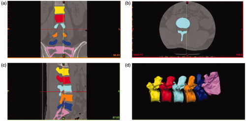
Due to the constrained effect of the spine during spinal surgery, the axial displacement of the spine is negligible and only considers the radial deformation of the spine. In order to get the relationship between the deformation and the force of the lumbar spine, the model of the spine which includes L1-L5 and sacrum for finite element analysis (FEA) is established. The CT data of the lumbar spine is obtained by using a series of computed tomography (1 mm intervals) from a man who is 30 years old and 173 cm tall. First, the CT data is imported into the Mimics software in DICOM format, and the spine contour image is extracted. Then the three-dimensional model is reconstructed, and the vertebrae (L1-L5) and sacrum are generated. As shown in , it is the basic model of the L1-L5 lumbar segment and the sacrum in MIMICS.
Figure 4. Basic model of the L1-L5 lumbar segment and the sacrum in MIMICS.
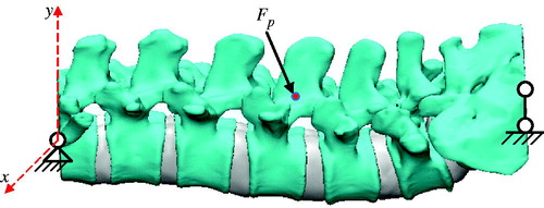
The CT scan data can only obtain image data of lumbar vertebrae and sacrum while the image data of intervertebral disc can’t be obtained. So the 3-matic software is used to draw the intervertebral disc, which combined with the vertebral part and the sacrum seamlessly. And the intervertebral disc also consists of the nucleus pulposus, the annulus fibrosus and cartilage endplate. As shown in , it is the structure of the lumbar spine which includes the lumbar vertebral body, the intervertebral disc and the sacrum. And it also shows the force and restraints on the lumbar spine.
Figure 5. Structure of the lumbar spine which includes the lumbar vertebral body, the intervertebral disc and the sacrum.
In Abaqus, according to the biomechanical studies of FEA condected on the lumbar spine [Citation18–22], the material and section properties are given to the vertebral body, nucleus pulposus, annulus fibrosus and cartilage endplate. And the material properties for the FEA model are set in .
According to the actual anatomical structure of the vertebral body of the human body, the parts of the lumbar spine are assembled in the relative position of the space and the contact surface is determined. The contact between the vertebral body and the intervertebral disc is defined as the "tie" model without relative displacement and the surface of the vertebral body as the main surface and the surface of the intervertebral disc as the slave surface. The finite element model is hinged at the ends of thoracic vertebra and sacrum, and the concentrated force acts on the middle of model with different sizes and angles to the y axis.
Table 1. Material properties of the FEA model.
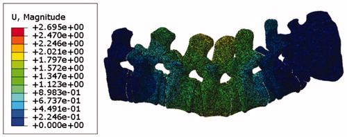
As shown in , it is the displacement nephogram of the lumbar spine which is subjected to the concentrated force of 50 N in the finite element simulation. It can be seen from the simulation results that the displacement of each point on the surface of the finite element model is mainly distributed in the range of 0 to 3 mm.
Figure 6. Displacement nephogram of the lumbar spine subjected to the concentrated force in the finite element simulation.
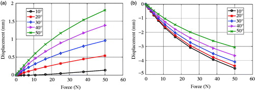
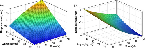
When the surgical instrument acts on the lumbar spine, it can be bent and twisted. And the deformation mainly occurs in the x axis and y axis and the deformation of z axis is so small that can be neglected. So the next step is to research the change of the displacement in the direction of x and y. The displacement of the point on the finite element model along the x axis and y axis under the concentrated force can be obtained from the finite element simulation. As shown in , it is the relationship curve between the force and displacement which in the different size of concentrated force and different angles to the y axis. It can be seen clearly that the displacement of the x axis and y axis have non-linear relationships with the concentrated force. As the force increases, the change of the displacement of the lumbar spine gradually slows down, and the lumbar spine can be damaged once the load exceeds the critical value of the strength of the lumbar spine. The applied force is within the range that the spine can withstand. Therefore, the failure and damage of the finite element model need not be considered.
Figure 7. Non-linear relationship of the concentrated force and displacements in x and y directions in the finite element environment.
III.Mathematical modeling of lumbar spine
A series of input and output data are obtained by the finite element simulation, and then the response surface methodology is used to fit the function relationship between the input and output data. The response surface methodology not only involves the content of the experimental design, but also involves some knowledge of statistics. The method of the central composite design is the most commonly used two order design in response surface analysis and it is used to optimize and analyse the response surface in this paper.
The Design-Expert is the software for response surface analysis. First of all, according to the result of the finite element simulation, the independent variables are force and the angle between the force and the y axis which are the input data and the dependent variable is the displacement of the spine which is the output data. The quadratic polynomial equation is used as the fitting equation which contains the constant term, the first term and the second term (including the interaction term). Then, the corresponding fitting equation is obtained based on the analysis of variance.
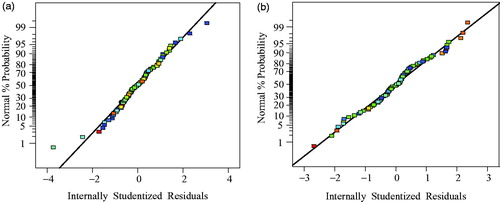
As shown in , it is the normal probability distribution of residuals. These points basically satisfy the requirement of distributing in a straight line.
Figure 8. Normal probability distribution of residuals.
As shown in , after a series of operation of the data in the software, the three-dimensional response surface map is obtained. And the relationship between the concentrated force, angle and displacement can be seen through the three-dimensional response surface map which is non-linear.
Figure 9. Three-dimensional response surface map.
The quadratic polynomial equation is used as the fitting equation, and the fitting equations of the x-axis and y-axis of the spine deformation are finally obtained. It can be represented by the following formula:
(1)
(1)
where,
is the concentrated force which acts on the middle of the lumbar spine. α is the angle between the force and the y axis, and is calculated by radians.
IV.Simulation and results
In order to verify the feasibility of the established mathematical model, position-based control is used to describe the interaction of the robot and the spine. As shown in , it is the block diagram of the compensation control system.
Figure 10. Block diagram of the compensation control system.
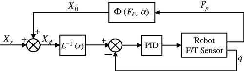
The PID is used to control the joint position of the robot in inner loop and outer loop is for the compensation of spinal deformation. The is the mathematical model and the force
is measured by the force sensor to calculate the displacement of the spinal deformation, and then fed back to the input signal.
is the desired location and
is the actual location to be controlled during surgery.
is the inverse kinematics of the robot, which transforms the displacement of the joint into the position in Cartesian space.
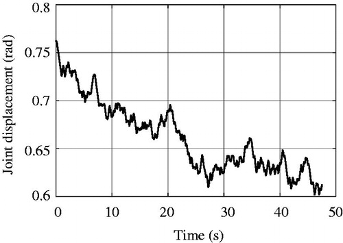
In order to make the simulation results more accurate, the control system is systematically identified and then the transfer function of the system is obtained. The input signal uses the M-sequence pseudorandom signal which is independent of the output measurement noise. As shown in , it is the generated pseudorandom sequence input signal. And as shown in , it is the experimentally measured joint displacement curve.
Figure 11. Generated pseudorandom sequence input signal.
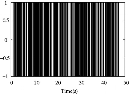
Figure 12. Experimentally measured joint displacement curve.
The system identification toolbox in MATLAB is used to identify the system. According to the input and output data of the experimental system, after filtering the data, and then identify the transfer function. Finally, the transfer function of the system is obtained as follows.
(2)
(2)
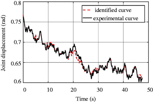
As shown in , it is the identified curve and the experimental curve of the system.
Figure 13. Identified curve and experimental curve of the system.
The Simulink module of MATLAB is used to simulate the control system and the transfer function is used as the transfer function of the robot. As shown in , it is the simulation model of control system in Simulink.
Figure 14. Simulation model of the control system in Simulink.
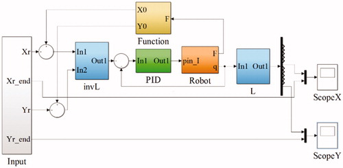
The subsystem ‘Robot’ uses the six degree of freedom manipulator. And the subsystem ‘Input’ is the desired signals in the x direction and the y direction which are both sinusoidal signals. The starting time is 0 s, and the simulation step is 0.01 s, and the simulation time is 10 s. The trajectory tracking for simulation model of control system in Simulink is shown in .
Figure 15. Trajectory tracking curve at the end of the manipulator.
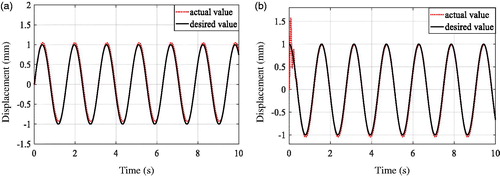
From the simulation results, it can be clearly seen that the trajectory changes of the end position of the manipulator are well following the expected trajectory changes, and with the increase of simulation time, the position tracking error is also decreasing. The result of the simulation shows that the mathematical model established in this paper is valid.
V.Conclusion
For spinal surgery, the force generated by the surgical instruments and the spine can deform the spine. This paper presents a method of using response surface methodology to establish the relationship between force and displacement based on the results of the finite element simulation. The three-dimensional model of lumbar spine is reconstructed by CT scan data and then the lumbar spine is analysed by finite element method. The intervertebral disc which includes nucleus pulposus, annulus fibrosus and endplate is the main structure that leads to deformation. In order to verify the feasibility of the established mathematical model, the simulation of the control system is carried out. By comparing the trajectory curves at the end of the manipulator, the validity of the mathematical model is verified. In the future, when the experimental conditions are sufficient, the experiments will be carried out on the cadaver torsos to verify the idea.
Disclosure statement
No potential conflict of interest was reported by the authors.
Additional information
Funding
References
- González ME, García-Cosamalón J, Cosamalón-Gan I, et al. Biology and mechanobiology of the intervertebral disc. Neurocirugía. 2017;28:135.
- Peng X, Wang Y, Shi S, et al. Biomechanical analysis of lumbar interbody fusion with an anisotropic hyperelastic model for annulus fibrosis. Arch Appl Mech. 2013;83:579–590.
- Low AL, Müller-Karger C, Zambrano L. Sensibility analysis of the material properties applied to an intervertebral disc model. Health Care Exchanges. IEEE. INSPEC Accession Number: 13681714. 2013;1–5.
- Badilatti SD, Christen P, Parkinson I, et al. Load-adaptive bone remodeling simulations reveal osteoporotic microstructural and mechanical changes in whole human vertebrae. J Biomech. 2016;49:3770.
- Virgin WJ. Experimental investigations into the physical properties of the intervertebral disc. J Bone Joint Surg British. 1951;33-B:607.
- Brown T, Hansen RJ, Yorra AJ. Some mechanical tests on the lumbosacral spine with particular reference to the intervertebral discs; a preliminary report. J Bone Joint Surg Am Vol. 1957;39:1135–1164.
- Farfan HF, Cossette JW, Robertson GH, et al. The effects of torsion on the lumbar intervertebral joints: the role of torsion in the production of disc degeneration. J Bone Joint Sur Am Vol. 1970;52:468.
- Farfan HF, Huberdeau RM, Dubow HI. Lumbar intervertebral disc degeneration: the influence of geometrical features on the pattern of disc degeneration–a post mortem study. J Bone Joint Surg Am Vol. 1972;54:492.
- Markolf KL. Deformation of the thoracolumbar intervertebral joints in response to external loads: a biomechanical study using autopsy material. J Bone Joint Surg Am Vol. 1972;54:511.
- Markolf KL, Morris JM. The structural components of the intervertebral disc. A study of their contributions to the ability of the disc to withstand compressive forces. J Bone Joint Surg Am Vol. 1974;56:675.
- Viviani GR, Ghista DN, Lozada PJ, et al. Biomechanical analysis and simulation of scoliosis surgical correction. Clin Orthop Related Res. 1986;208:40–47.
- Sonnerup L. Stress and strain in the intervertebral disc in relation to spinal disorders. In: Ghista DN, editor. Osteoartho mechanics. New York: McGraw-Hiu; 1980. p. 27–35.
- Belytschko T, Kulak RF, Schultz AB, et al. Finite element stress analysis of an intervertebral disc. J Biomech. 1974;7:277.
- Liu YK, Ray G, Hirsch C. The resistance of the lumbar spine to direct shear. Orthopedic Clin North America. 1975;6:33–49.
- Furlong DR, Palazotto AN. A finite element analysis of the influence of surgical herniation on the viscoelastic properties of the intervertebral disc. J Biomech. 1983;16:785–795.
- Zander T, Rohlmann A, Calisse J, et al. Estimation of muscle forces in the lumbar spine during upper-body inclination. Clin Biomech. 2001;16:S73–S80.
- Rohlmann A, Bauer L, Zander T, et al. Determination of trunk muscle forces for flexion and extension by using a validated finite element model of the lumbar spine and measured in vivo data. J Biomech. 2006;39:981–989.
- Rohlmann A, Zander T, Schmidt H, et al. Analysis of the influence of disc degeneration on the mechanical behaviour of a lumbar motion segment using the finite element method. J Biomech. 2006;39:2484–2490.
- Ruberte LM, Natarajan RN, Andersson GB. Influence of single-level lumbar degenerative disc disease on the behaviour of the adjacent segments-a finite element model study. J Biomech. 2009;42:341–348.
- Goel VK, Monroe BT, Gilbertson LG, et al. Interlaminar shear stresses and laminae separation in a disc. Finite element analysis of the L3-L4 motion segment subjected to axial compressive loads. Spine (Phila Pa 1976). 1995;20:689–698.
- Shirazi-Adl A, Ahmed AM, Shrivastava SC. Mechanical response of a lumbar motion segment in axial torque alone and combined with compression. Spine (Phila Pa 1976). 1986;11:914–927.
- Ueno K, Liu YK. A three-dimensional nonlinear finite element model of lumbar intervertebral joint in torsion. J Biomech Eng. 1987;109:200–209.