
 ?Mathematical formulae have been encoded as MathML and are displayed in this HTML version using MathJax in order to improve their display. Uncheck the box to turn MathJax off. This feature requires Javascript. Click on a formula to zoom.
Abstract
Percutaneous needle puncture operation is widely used in the image-guided interventions, including biopsy and ablation. MRI guidance has the advantages of high-resolution soft tissue imaging and thermal monitoring during energy-based ablation. This paper proposes the design of a 5-DOF pneumatic needle puncture robot, with all the cylinders, sensors and structure material MRI-compatible. Also, a hybrid fuzzy-PID controller is designed for the pneumatic driven system to adjust the PID parameters adaptively. The experiment validation result shows that, compared with the traditional fix-parameter PID control, the proposed hybrid fuzzy-PID control has no overshoot, and the settle time/steady state error remains low even with increasing load. This proves that the hybrid fuzzy-PID control strategy can increases the positioning accuracy and robustness of the pneumatic driven needle puncture robot, which is significant for the safety of percutaneous needle puncture operation.
Introduction
Percutaneous needle puncture operation is the basis of image-guided interventions, which is using a needle to establish a channel to the target tissue location inside the human body, and the surgeon completes diagnosis and treatment operations through this channel [Citation1]. The guiding image can be ultrasound, CT or MRI; compared to the first two image modes, MRI has excellent soft tissue resolution and is without radiation, furthermore, it enables thermal monitoring during cryoablation or microwave ablations, which greatly improves the safety of tumor treatment. These advantages make MRI to be a preferred guiding image mode for needle puncture operation [Citation2,Citation3]. However, due to the limited accessibility of MRI machine, surgeon needs to take patients outside the scanner bore during the manual needle puncture operation and push them back for image rescanning to affirm the puncture target, which is time-consuming; and the frequent movement of patients also decreases the accuracy of procedure [Citation4]. An assistant robot, with advantages of accurate positioning and high stability, will allow percutaneous needle puncture operation being conducted inside the scanner bore and the subsequent rescanning being completed continuously, improving the procedure accuracy and efficiency [Citation5,Citation6].
For MRI-guided needle puncture robot, its working environment is a magnetic field of 1.5 T to 3.0 T. The strong magnetic field limits the use of devices containing ferromagnetic materials. Therefore, traditional motors with electromagnetic working principle cannot be used directly on robots. Also, the material of robots cannot deteriorate the MR imaging quality [Citation7,Citation8]. Gassert built a remote control MRI-compatible robot, with DC motors driving a pair of master cylinders in the control room, and the power was transmitted to the corresponding slave cylinders in the scanner room with hydrostatic infrastructure [Citation9], this method solves the limitation of traditional motors under MRI environment by placing them faraway, but reduces the accuracy and efficiency of robotic system. Researchers also proposed to use ultrasonic motors to drive robots, whose working principle are based on resonant vibrations of non-magnetic piezoceramic, and do not require electromagnetic fields to operate, but the electrical circuitry to produce the high voltages driving motors can distort the MR images, which requires further electromagnetic shielding [Citation10]. Song developed a needle guiding robot for MRI-guided targeted prostate biopsy with ultrasonic motors, and showed a maximum of 44% signal-to-noise (SNR) ratio decrease on MR images when the ultrasonic motors were running [Citation11]. Krieger developed a needle guiding robot for MRI-guided transrectal needle access of prostate with ultrasonic motors, and showed a reduction by 80% to the SNR on MR images when enabling the motors, and a reduction by 40–60% with RF shielding [Citation12]. Su and Li designed a novel motor driver without high frequency switching signal for ultrasonic motor, and the robot system with this kind of motor achieve less than 15% SNR ratio reduction [Citation13,Citation14]. Another driving method for MRI-compatible robot is hydraulic or pneumatic drive. Kokes designed a 1-DOF MRI-compatible needle driver robot with hydraulic drive, and showed almost no artifact to the MR images [Citation15]. Compared with hydraulic drive, pneumatic drive is cleaner, and the working medium is easier to obtain, these advantages make it to be widely used in MRI-compatible robots. With commercially available cylinders, Jiang designed a 5-DOF needle insertion robot for prostate interventions [Citation16], Franco designed a 4-DOF needle guiding robot for laser ablation of liver tumors [Citation17], both of robots showed negligible MR image artifact. Bricault and Tse built MRI-compatible robots with custom-developed pneumatic air motors, though the novel motor design is complex and costly [Citation18,Citation19].
Pneumatic drive is suitable for MRI-compatible robots, but due to the inherent compressibility of air, the nonlinearity of air flow through valve ports, and cylinder friction, it is difficult to achieve high accuracy for the pneumatic position control, which is the main challenge to the pneumatic driven robot. Song applied traditional PID control on a 4-DOF pneumatic robot for MRI-guided transperineal prostate biopsy and brachytherapy, and the proportional, integral, and derivative gains for each cylinder were individually tuned for the highest possible positioning accuracy [Citation20]. Melzer used standard PID controller on a 5-DOF pneumatic robot for MRI-guided percutaneous interventions [Citation21]. However, because of the high nonlinearity and time-varying uncertainties of pneumatic servo systems, fixed-parameter PID control does not guarantee that the system will achieve ideal control performance at different operating points, especially under variable loading conditions. Yang designed sliding mode control on a 1-DOF pneumatic driven robot for breast tumor ablation, and the friction was treated as an uncertainty term to drive the system onto the sliding surface [Citation22]. Franco designed an optimized sliding mode control scheme on a 3-DOF pneumatic needle positioning robot for liver tumor ablation, and two saturation functions were used together to compensate friction [Citation23]. Franco designed a time delay control scheme using the back-stepping technique on a 4-DOF pneumatic needle guiding robot to achieve high position accuracy without requiring pressure or force measurements [Citation24].
This paper proposes the design of a 5-DOF pneumatic needle puncture robot with commercially available cylinders. To be located in the scanner bore, the robot has a compact configuration. To meet the requirement of MRI compatibility, the cylinders are chosen to be MRI-compatible, and the material used to fabricate the robot is aluminum alloy or brass. Also, the lasers with plastic packaging, rather than traditional encoders with ferromagnetic materials, are selected as distance sensors. To solve the problem that fixed-parameter PID algorithm does not guarantee ideal control performance at different operating points, a hybrid fuzzy-PID control scheme is proposed to adjust the PID parameters adaptively based on the positioning error in real time.
This paper is organized as follows. Section II introduces the robot design and its kinematics analysis. Section III describes the design of the hybrid fuzzy-PID controller and its simulation testing results. Section IV reports the robot positioning accuracy experiment result under variable loading conditions. Section V gives concluding remarks.
Robot design and kinematics
The proposed needle puncture robot has five actuated degrees of freedom (). The first cylinder and the second cylinder form a pair, providing the needle guide with translation along x axis (move together) and rotation around y axis (move differently). The third cylinder and the fourth cylinder form a second pair, providing the needle guide with translation along y axis (move together) and rotation around x axis (move differently). The two pairs of cylinders are in series, serving as the positioning unit of the needle guide. The needle guide has the fifth cylinder inside, which drives the needle to do the puncture motion along the desired orientation.
Figure 1. The CAD model of the pneumatic needle puncture robot.
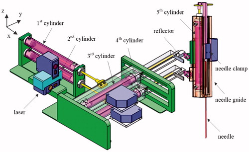
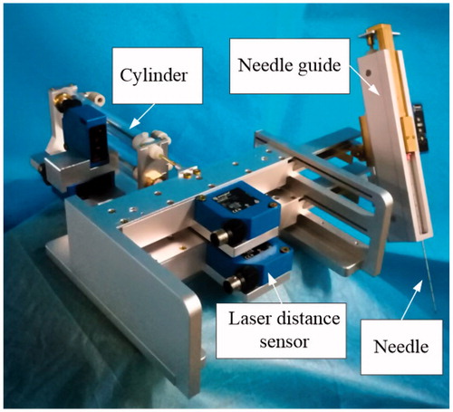
All the cylinders are MRI-compatible (AC 13270-2, Airpot Corporation), with stroke 101.6 mm. Each cylinder is with a laser distance sensor (CP35MHT80, wenglor sensoric GmbH), and a reflector is attached at the end of the piston, to reflect the laser beam. The first pair of cylinders is fixed on the supporting base, and drives the second pair of cylinders to slide along the guiding rail on the supporting base. The needle guide is attached with the second pair of cylinders with two universal joints, which allows orientation adjustment of the needle guide. Since the distance between the two universal joints will change when the positioning cylinders move, one of the universal joints is connected with the needle guide with a sliding joint. For structure compactness, the fifth cylinder in the needle guide is arranged in the way that the needle does the puncture motion when the driving cylinder retracts its piston, so the needle clamping mechanism won’t occupy any precious space below the needle guide, where the patients are located. Each cylinder is controlled by two proportional valves (ITV2050-212L, SMC Corporation), which has pressure sensor equipped, and works at pressure around 0.25Mpa. shows the fabricated prototype of the pneumatic needle puncture robot.
Figure 2. Prototype of the pneumatic needle puncture robot.
shows the kinematic relation of the needle puncture robot. The origin of coordinate is set at the center of the first cylinder base. The length of each cylinder bore is L1, and the distance between the first pair of cylinders is L2. The two universal joints are both parallel with the first pair of cylinders (along x axis), with length L3. The distance between P2 (the connecting point of the lower universal joint and the needle guide) and the lower side of needle guide is represented by L4. The travel distance of each cylinder is represented by di (i = 1, 2, 3, 4, 5), and the maximum is represented by dmax. Since the needle will be retracted just inside the needle guide when the fifth cylinder is at its maximum travel distance, the puncture depth of the needle is dmax−d5. With this setting, the coordinate of P1 (the connecting point of the upper universal joint and the needle guide) will be (L1+L3+d1, L1+d3, 0), the coordinate of P2 will be (L1+L3+d2, L1+d4, −L2). Since the needle tip P3 is in line with P1 and P2, the coordinate of P3 will be,
(1)
(1)
Figure 3. Kinematics of the needle puncture robot.
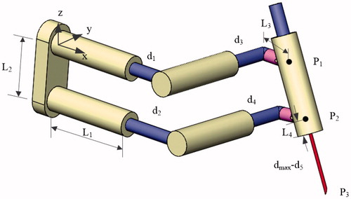
Based on the hardware in the prototype, the length of cylinder bore L1 = 183.5 mm, the stroke dmax=101.6 mm, the distance between the first pair of cylinders L2 = 33 mm, the length of universal joint L3 = 78 mm, the distance between P2 and the lower side of needle guide L4 = 48 mm. Therefore, the position adjusting range of the needle guide is 0∽101.6 mm along x and y axes, the orientation adjusting range of the needle guide is around x and y axes, the needle puncture motion range is 0∽101.6 mm.
Hybrid fuzzy-PID controller design
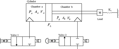
shows the schematic of a single cylinder actuation. The cylinder has two unsymmetrical chambers, each with pressure Pi, cross area Ai and volume Vi, i= {a, b}. The cylinder is with load ML, and the stiffness coefficient between load and environment is KL. Based on the second Newton’s law, the dynamic equation of the cylinder actuation is obtained,
(2)
(2)
Figure 4. Schematic of a single cylinder actuation.
Usually, the traditional fixed-parameter PID controller cannot avoid overshoot, and variable loading/friction condition will also affect the positioning accuracy. This is not acceptable for surgical application, which requires high accuracy and robustness in all occasions. A hybrid fuzzy-PID controller is proposed to adjust the PID parameters adaptively, thus increase the positioning accuracy of the needle puncture robot, as shown in .
Figure 5. Hybrid fuzzy-PID controller design.
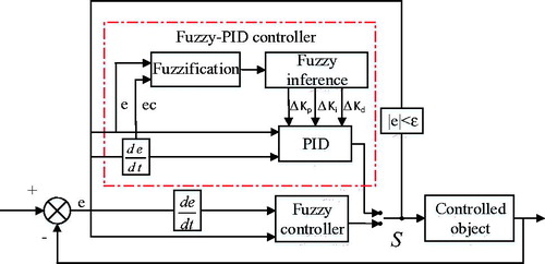
The hybrid fuzzy-PID controller is mainly composed of fuzzy controller and adaptive fuzzy-PID controller. When the position error is larger than a threshold ε, fuzzy controller is applied, to ensure the moving quick and with no overshoot. The threshold ε is preset constant, in this paper it is set as 5 mm. After the cylinder arrives nearby the target position, fuzzy-PID controller is applied, to ensure the moving with no steady state error. The position error e and its changing rate ec are used as the inputs of the hybrid fuzzy-PID controller. The correction amount of proportional gain ΔKp, integral gain ΔKi, and derivative gain ΔKd are calculated as the output of the fuzzy inference and added to their initial values, and used as the new PID parameters in the next control cycle. The fuzzy rules are designed so that the PID parameters become larger with large position error e and changing rate ec, and become smaller with small position error e and changing rate ec.
To show the effectiveness of the proposed hybrid fuzzy-PID controller, compared with traditional fix-parameter PID controller, simulation with increasing load 0 N, 0.5 N, 1.0 N, 1.5 N and 2.0 N are conducted with Matlab and Simulink for both controller, as shown in and . and show the performance index change for the two controllers. It is noticed that, as the load increases, the overshoot increases from 17% to 25%, the settling time increases from 0.11 s to 0.72 s, while the steady state error remains zero. The performance becomes worse as the load increases. Compared to the fix-parameter PID controller, the proposed hybrid fuzzy-PID controller has no overshoot and zero steady state error, and the settle time remains constant, which shows better positioning accuracy and higher robustness.
Figure 6. Simulation of fix-parameter PID control with increasing load.
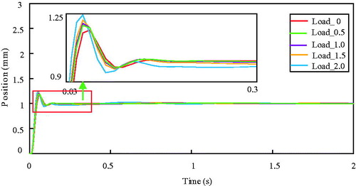
Figure 7. Simulation of hybrid fuzzy-PID control with increasing load.
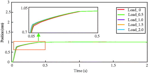
Table 1. Performance index in simulation with increasing load for fix-parameter PID control.
Table 2. Performance index in simulation with increasing load for hybrid fuzzy-PID control.
Experiment validation
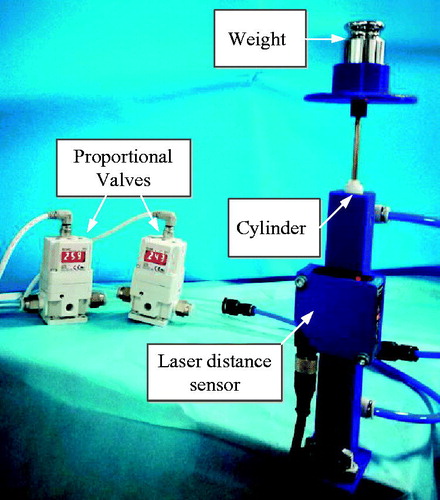
To validate the performance of the proposed hybrid fuzzy-PID controller, experiment with increasing load is conducted on a single cylinder. For the purpose of comparison, the fix-parameter PID control is also tested. The experiment setup is shown in . The cylinder is mounted vertically, which is similar to the case for needle puncture motion’s loading condition, and driven by two proportional valves; the displacement of the cylinder is measured by laser distance sensor. Increasing load 0 N, 0.5 N, 1.0 N, 1.5 N and 2.0 N are tested separately on the cylinder actuation system. The control algorithms run on a microcontroller (Arduino UNO) at 100 Hz frequency. The initial proportional, integral, and derivative gains for both controllers are manually tuned with empty loading condition.
Figure 8. Experiment setup with increasing load.
shows the experiment result for fix-parameter PID control. It is noticed that, with load increases, the overshoot increases from 10% to 110%, the settling time increases form 0.2 s to 6.4 s, and the steady state error is around 1.5 mm, as shown in . By contrast, the proposed hybrid fuzzy-PID control has no overshoot; the settling time increases from 0.1 s to 1.8 s, keeping at a low level; the steady state error remains around 1 mm, which is similar to that of fix-parameter PID control, as shown in and .
Figure 9. Experiment result of fix-parameter PID control with increasing load.
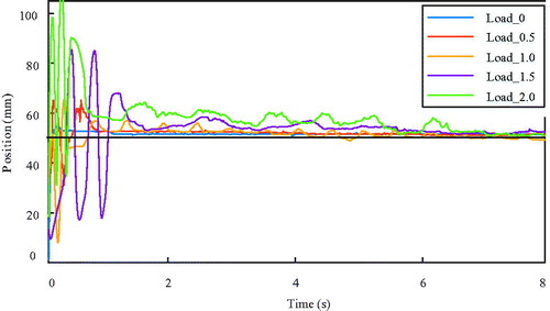
Figure 10. Experiment result of hybrid fuzzy-PID control with increasing load.
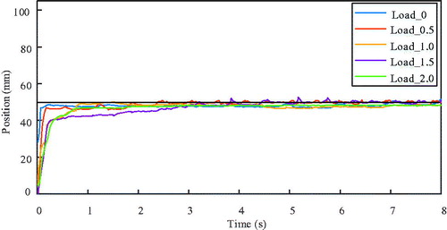
Table 3. Performance index in experiment with increasing load for fix-parameter PID control.
Table 4. Performance index in experiment with increasing load for hybrid fuzzy-PID control.
Conclusion
This paper proposed a 5-DOF MRI-compatible needle puncture robot, which is driven by commercially available cylinders, the laser distance sensor and aluminum alloy/brass structure material ensures the MRI compatibility of the robot. The robot is with series-parallel structure, the first four joints are to adjust the posture of the needle, and the last joint is to control the control the puncture motion. The robot has a compact configuration, which enables it to work in the MRI scanner bore. This allows the percutaneous needle puncture operation be conducted inside the scanner bore and the subsequent rescanning be completed continuously, improving the procedure accuracy and efficiency.
For the position control of the robot, a hybrid fuzzy-PID control strategy is proposed. Compared with the traditional fix-parameter PID control, the novel controller has no overshoot, and the settle time/steady state error remains low even with increasing load, thus increases the positioning accuracy and robustness of the pneumatic driven system. This is of great significance for safety of the needle puncture operation.
In future work, MRI compatibility test for the designed robot will be conducted and image deterioration due to the existence of the robot will be evaluated. Also, the MRI image processing and registration will be added to the robot system, and image guided needle puncture experiment on phantom will be conducted. Gas tanks will be connected between the cylinder and its driving valves, to reduce the turbulence in cylinder chambers, thus increase the position control stability of the needle puncture robot.
Disclosure statement
No potential conflict of interest was reported by the authors.
Additional information
Funding
References
- Chan KG, Fielding T, Anvari M. An image-guided automated robot for MRI breast biopsy. Int J Med Robot. 2016;12:461–477.
- Gedroyc WM. Magnetic resonance guidance of thermal ablation. Top Magn Reson Imaging. 2005;16:339–353.
- Kettenbach J, Kronreif G, Melzer A, et al. Ultrasound-, CT-and MR-guided robot-assisted interventions. Image Processing in Radiology. Berlin (Heidelberg): Springer; 2008. p. 393–409.
- Abdullah BJJ, Yeong CH, Goh KL, et al. Robot-assisted radiofrequency ablation of primary and secondary liver tumours: early experience. Eur Radiol. 2014;24:79–85.
- Kettenbach J, Kara L, Toporek G, et al. A robotic needle-positioning and guidance system for CT-guided puncture: ex vivo results. Minim Invasiv Ther. 2014;23:271–278.
- Wang W, Shi Y, Goldenberg AA, et al. Experimental analysis of robot-assisted needle insertion into porcine liver. Biomed Mater Eng. 2015;26:375–380.
- Fischer GS, Iordachita I, Csoma C, et al. MRI-compatible pneumatic robot for transperineal prostate needle placement. IEEE/ASME Trans Mechatron. 2008;13:295–305.
- Hempel E, Fischer H, Gumb L, et al. An MRI-compatible surgical robot for precise radiological interventions. Comput Aided Surg. 2003;8:180–191.
- Elhawary H, Tse ZTH, Hamed A, et al. The case for MR-compatible robotics: a review of the state of the art. Int J Med Robot. 2008;4:105–113.
- Wang WD, Zhang P, Shi YK, et al. Design and compatibility evaluation of magnetic resonance imaging-guided needle insertion system. J Med Imaging Inform. 2015;5:1963–1967.
- Song SE, Tokuda J, Tuncali K, et al. Development and preliminary evaluation of a motorized needle guide template for MRI-guided targeted prostate biopsy. IEEE T Bio-Med Eng. 2013;60:3019–3027.
- Krieger A, Song SE, Cho NB, et al. Development and evaluation of an actuated MRI-compatible robotic system for MRI-guided prostate intervention. IEEE/ASME Trans Mechatron. 2013;18:273–284.
- Su H, Shang W, Cole G, et al. Piezoelectrically actuated robotic system for MRI-guided prostate percutaneous therapy. IEEE/ASME Trans Mechatron. 2015;20:1920–1932.
- Li G, Su H, Cole G, et al. Robotic system for MRI-guided stereotactic neurosurgery. IEEE T Bio-Med Eng. 2015;62:1077–1088.
- Kokes R, Lister K, Rao G, et al. Towards a needle driver robot for radiofrequency ablation of tumors under continuous MRI. Proceedings of the IEEE International Conference on Robotics and Automation; 2008. May 19–23; Pasadena, USA. IEEE; 2008. p. 2509–2514.
- Jiang S, Feng W, Lou J, et al. Modelling and control of a five-degrees-of-freedom pneumatically actuated magnetic resonance‐compatible robot. Int J Med Robotics Comput Assist Surg. 2014;10:170–179.
- Franco E, Brujic D, Rea M, et al. Needle-guiding robot for laser ablation of liver tumors under MRI guidance. IEEE/ASME Trans Mechatron. 2016;21:931–944.
- Bricault I, Zemiti N, Jouniaux E, et al. Light puncture robot for CT and MRI interventions: designing a new robotic architecture to perform abdominal and thoracic punctures. IEEE Eng Med Biol Mag. 2008;27:42–50.
- Tse ZTH, Elhawary H, Zivanovic A, et al. A 3-DOF MR-compatible device for magic angle related in vivo experiments. IEEE/ASME Trans Mechatron. 2008;13:316–324.
- Song SE, Cho NB, Fischer G, et al. Development of a pneumatic robot for MRI-guided transperineal prostate biopsy and brachytherapy: New approaches. Proceedings of IEEE International Conference on Robotics and Automation; 2010 May 3–7; Anchorage, USA. IEEE; 2010. p. 2580–2585.
- Melzer A, Gutmann B, Remmele T, et al. Innomotion for percutaneous image-guided interventions: principles and evaluation of this MR- and CT-compatible robotic system. IEEE Eng Med Biol Mag. 2008;27:66–73.
- Yang B, Tan UX, Mcmillan A, et al. Design and control of a 1-DOF MRI compatible pneumatically actuated robot with long transmission lines. IEEE/ASME Trans Mechatron. 2011;16:1040–1048.
- Franco E, Ristic M. Design and control of needle positioner for MRI-guided laser ablation of the liver. Proceedings of IEEE/ASME International Conference on Mechatronic and Embedded Systems and Applications; 2014. Sep 10–12; Senigallia, Italy. IEEE; 2014, p. 1–6.
- Franco E, Ristic M. Time delay controller for the position control of a MRI-compatible pneumatic actuation with long supply lines. Proceedings of IEEE/ASME International Conference on Advanced Intelligent Mechatronics; 2014; Jul 8–11; Besacon, France. IEEE; 2014, p. 683–689.