
 ?Mathematical formulae have been encoded as MathML and are displayed in this HTML version using MathJax in order to improve their display. Uncheck the box to turn MathJax off. This feature requires Javascript. Click on a formula to zoom.
Abstract
Frame-based stereotaxy is widely used for planning and implanting deep-brain electrodes. In 2013, as part of a clinical study on deep-brain stimulation for treatment-resistant depression, our group identified a need for software to simulate and plan stereotactic procedures. Shortcomings in extant commercial systems encouraged us to develop Tactics. Tactics is purpose-designed for frame-based stereotactic placement of electrodes. The workflow is far simpler than commercial systems. By simulating specific electrode placement, immediate in-context view of each electrode contact, and the cortical entry site are available within seconds. Post implantation, electrode placement is verified by linearly registering post-operative images. Tactics has been particularly helpful for invasive electroencephalography electrodes where as many as 20 electrodes are planned and placed within minutes. Currently, no commercial system has a workflow supporting the efficient placement of this many electrodes. Tactics includes a novel implementation of automated frame localization and a user-extensible mechanism for importing electrode specifications for visualization of individual electrode contacts. The system was systematically validated, through comparison against gold-standard techniques and quantitative analysis of targeting accuracy using a purpose-built imaging phantom mountable by a stereotactic frame. Internal to our research group, Tactics has been used to plan over 300 depth-electrode targets and trajectories in over 50 surgical cases, and to plan dozens of stereotactic biopsies. Source code and pre-built binaries for Tactics are public and open-source, enabling use and contribution by the extended community.
Introduction
Framed stereotactic neurosurgery uses a frame with fiducial markers visible in mono- or multi-modal imaging attached to a patient’s skull to register the image-based and patient-based coordinate systems [Citation1]. Framed techniques remain the gold standard for accuracy compared to frameless systems [Citation2]. Framed stereotaxy is predominantly used for guiding lesion biopsies and implanting micro-electrode leads for deep-brain recording or deep-brain stimulation (DBS) for the investigation and treatment of epilepsy, chronic pain, depression, and movement disorders [Citation3].
Parkinson’s disease and other movement disorders are estimated to affect 2.75 million people in the United States [Citation4]. In approximately 10–20% of cases of major depression – the most common of all psychiatric disorders – patients fail to respond to standard intervention methods; DBS has been proposed as an effective treatment for these patients [Citation5]. Recent estimates of the number of DBS implantations world-wide for all of these pathologies have been reported as 40,000 [Citation2].
In stereotactic procedures, surgeons use preoperative imaging data to plan positions and trajectories for electrode or biopsy targets using methods ranging from pen-and-paper calculations to the use of commercial software suites. These methods are deficient due to their inability to effective plan and visualize multiple penetration trajectories, their inability to robustly locate the stereotactic frame in preoperative imaging, and their inability to show individual electrode contacts. The ability to visualize many different trajectories is useful even in single lead or bi-lateral procedures, as alternative trajectories can each be visually explored and compared before a final selection of only the most effective trajectories for the procedure. Unused alternative trajectories may remain in the preoperative plan, though clearly marked as unused, to maintain a record of explored alternatives. Incorporating models of the specific implanted electrodes allows the simulation of electrode insertion to maximize the accurate placement of each individual electrode contact. Since the complication rate of electrode insertion is directly related to the number of cortical punctures, this allows the maximal utility per electrode trajectory to be attained. Some commercial applications allow the user to visualize individual leads, but these applications often partner with specific lead manufacturers, which limits the utility of the feature to users that do not have those leads.
Accuracy of stereotactic procedures has a direct impact on clinical outcomes [Citation6–9]. Targeting errors are a result of compounded error throughout the procedure, beginning with a mean mechanical targeting accuracy of 0.35 mm for stereotactic frames [Citation10]. Additional error is introduced in the image acquisition and image processing stages, including acquisition parameters such as slice thickness, image distortion, and localization of the frame within the images [Citation6].
Efficacy of these procedures is not only a function of target localization error; surgeons must accurately plan electrode placements and trajectories to maximize the number of electrode contacts directly located in diagnostic or therapeutic targets. Therefore, an intuitive representation of the stereotactic domain and a set of effective planning features is critical to the use and adoption of tools [Citation6]. Given the deficiencies present in standard planning techniques, our research study required the development of a new software tool that would provide features that standard techniques lack, particularly the ability to visualize individual lead contacts when planning or simulating an operation. As well, we required a tool that could be used uniformly across the entire study. We present Tactics, a novel software platform for planning, simulating, and validating stereotactic procedures, that resulted from these requirements.
Methods
Tactics provides a unified workflow for planning, simulating, and validating stereotactic procedures. We present an example of how Tactics facilitates electrode insertion and describe the functional and experimental validation of system internals. We also demonstrate the application of Tactics as a stereotactic case validation and analysis tool for clinical and research use. Finally, we describe components of software engineering that contributed to achieving project objectives and a robust software system.
Electrode insertion with tactics
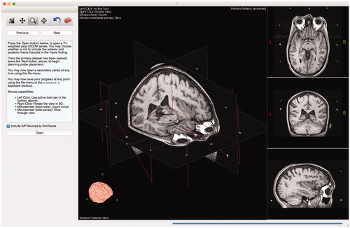
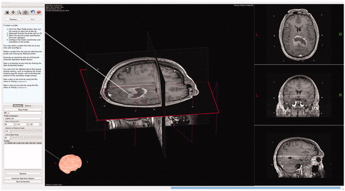
illustrates how Tactics supplements and improves the clinical workflow. On the day of surgery, surgeons attach a stereotactic frame to the skull of the patient and acquire tomographic images of the brain, typically using T1-weighted magnetic resonance (MR) or computed tomography (CT) scans. Surgeons import images of either modality into Tactics and the software automatically identifies and locates the stereotactic frame present in the images and transforms the coordinate system of the visualization scene to the coordinate system of the stereotactic frame. This transformation allows Tactics to present positions and trajectories of the electrode in the coordinates that are used to configure the frame during the procedure. The algorithm used to identify and locate the frame is presented in detail below. The system creates a volumetric representation of the images and presents an orthogonal cross-sectional view of the three-dimensional volume. Tactics automatically extracts the brain from the images using our own implementation of the Brain Extraction Tool algorithm [Citation11], and presents it as a volumetric model. demonstrates the scene shown to the surgeon after importing the images.
Figure 1. Tactics integrates directly into the electrode insertion workflow. The system enables surgeons to plan their procedures using preoperative images of the patient. Surgeons can export and bring with them to the operating room a procedure report containing a checklist of electrode specifications and trajectories to be performed. During the procedure, operating room staff can plan and log any changes required during the procedure. After the procedure, surgeons can compare electrodes in postoperative images with the trajectories planned prior to the procedure. Surgeons or researchers can use Tactics to quantify any deviations from the plans for case validation and research studies.
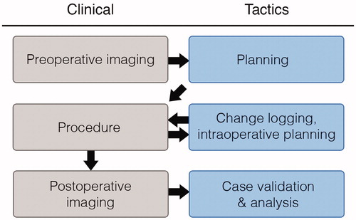
Figure 2. Scene generated by Tactics after importing preoperative images. The main view presents a volumetric representation of the data that can be observed by moving cross-sectional slices through the volume. The brain is automatically segmented from the images and is volumetrically rendered, as shown in the bottom left of the window. Fiducial markers of the stereotactic frame are identified as N-shaped fuchsia bars.
After the system has imported and segmented the image data, identified the stereotactic frame, and transformed the coordinate system of the scene, the surgeon is able to plan positions and trajectories of any number of electrodes as shown in and .
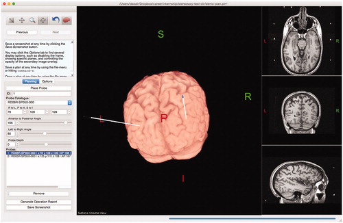
Figure 3. Example of surgical planning to implant deep-brain stimulation electrodes into subgenual cingulate for treatment of depression.
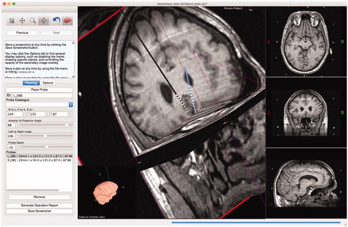
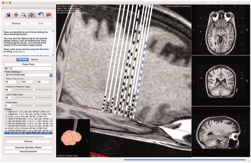
Figure 4. Tactics includes a user-extensible mechanism for planning with different lead specifications. Each lead design is a simple plaintext file that the system imports at startup. To include other lead designs, such as leads that match the designs of popular manufacturers, users need simply to create text files according to a simple format. By extending the catalog, users are able to plan, with much greater accuracy, positions of specific lead contacts to maximize surgical outcome.
To reduce hemorrhage risk, Tactics offers surgeons the ability to maximize and interact with the extracted brain view, or surface view, as shown in . This allows the cortical entry point to avoid sulci and vessels. Vessels are easily identified on gadolinium-enhanced T1-weighted MR acquisitions.
Figure 5. Users can maximize and interact with a surface view of the extracted brain, allowing them to visualize trajectories as they penetrate the brain. Modifications to the lead trajectories can be made in order to avoid cortical sulci or vessels.
When all electrode insertions have been simulated, the surgeon can save the plan and export an operation report, which lists all planned insertions including: the type of electrode, its frame-based coordinates, and its azimuth/declination angles. This operation report is used in the operating room and the procedure is performed, and the report is updated with the identification numbers of each inserted electrode. If it is found that a planned trajectory is not desirable in the OR, then Tactics can be used to plan or record an alternative trajectory.
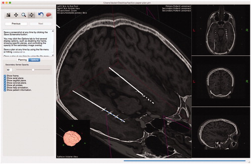
Surgeons often acquire postoperative MR or CT images to validate the placement of leads. Tactics enables the surgeon to import the postoperative images and the system will automatically perform a rigid registration to fuze them with the preoperative plan, as shown in . Surgeons can then compare and analyze the final versus planned lead trajectories and determine if tissues were effectively targeted.
Figure 6. Users can import a secondary series that will be registered and overlaid on the preoperative data. The opacity of the secondary overlay can be controlled (slider shown in left sidebar). The implanted leads and their contacts are clearly shown to match the trajectories of the planned leads.
Lead specification
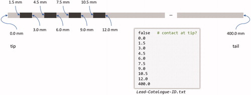
Tactics contains a user-extensible catalog for lead specifications. Any user of the software can extend the catalog by adding a plaintext file into a directory that the application watches at startup. The lead specification file format is simple – the user need only specify, using distance in millimeters from the lead tip, the edges of the lead contacts and whether or not the lead begins, at the tip, with a contact (). Having a user-extensible lead specification format allows any user (or group of users), to incorporate lead models to which they have access. As well, by having an extensible lead catalog, surgeons have the capability to design new leads that could provide more personalized care. One of our surgeons was recently able to add a new range of leads to our lead catalog, which consisted simply of adding a few simple text files to the lead specification directory.
Figure 7. A depiction and example of a lead specification file. The file format is simple – it consists of primarily two components: whether or not the tip is itself a contact, specified by a Boolean value at the beginning of the file, and a list of absolute distances (in mm) from the tip of the lead marking the beginning and ending of individual contacts. The final number represents the total length of the lead.
Handling of multiple volumes
Tactics currently allows for importing two volumes – a primary and a secondary. The secondary volume is registered to the primary through multi-modal rigid registration based on Mattes’ Mutual Information [Citation12,Citation13]. The purpose of the primary volume is for planning the procedure, and must contain the stereotactic frame, which is currently limited to the Leksell G-frame (Elekta AB, Stockholm, Sweden). The secondary volume does not need to contain the frame, as it is often a post-operative image used to validate the procedure. The secondary volume may, however, be any volume that can be successfully registered against the primary; it is not semantically restricted to a post-operative series.
Automatic frame localization
The Leksell G-frame has a removable fiducial box that fits around the patient’s head. Each side of the box, called a ‘plate’, has an N-shaped set of tubular fiducials. For MRI use, these are channels filled with copper sulfate solution, and for CT use they are made of metal. Our frame localization algorithm identifies these fiducials in MR or CT images via blob-selection, clustering, and fitting techniques that assign stereotactic coordinates to the images. Blob-selection, also known as connected-component labeling, is a common computer-vision technique for identifying pixels of interest in an image. The complete code behind our frame localization algorithm is published online with the rest of the software (https://git.io/fpoRG).
Our algorithm computes the histogram of the center 20 cm by 20 cm by 10 cm region of interest at the center of the image volume, and the threshold that includes 98% of the histogram area is found. This threshold, t98, allows us to exclude extremely bright pixels that are outliers due to artifacts or noise present in the images, and the use of a fixed-size region of interest avoids biasing the threshold toward the background pixel value. A second threshold at half of this value serves to discriminate between ‘bright’ and ‘dark’ pixels.
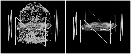
Blob-selection is performed on each of the axial slices using these thresholds. Each blob in the image is defined as a set of adjacent bright pixels (4-connected with signal > ½ t98) that have a total area less than or equal to 24 mm2, which corresponds to a circle of 5.5 mm diameter. Furthermore, all pixels with a signal above t98 are set to t98 to avoid biasing the blob centroid toward outliers. When a blob is found, its centroid is stored, along with the number of pixels in the blob and the average intensity of those pixels. The result of blob selection and centroid calculation, shown in the left of is that all small bright dots in the image are identified.
Figure 8. Blob selection (left) and cluster selection (right). Each cluster of blobs that corresponds to a tube undergoes principal component analysis. A single slice of the brain is shown for reference. It is typical for there to be some residual geometric distortion after correcting for the nonlinear gradient fields.
The blobs that belong to each fiducial plate are then clustered, and then the sub-clusters that belong to the three individual fiducial lines are identified. To identify the right and left plates, all of the blob centroids are projected onto the X-axis to create a signal versus position plot () in which the plates appear as two peaks with a nominal separation of 196 mm. We allow a tolerance of ±10 mm to account for rotation and image distortion. The blobs within the right peak are then projected onto the Y-axis (the anterior-to-posterior axis) and separately onto a 45° diagonal. The results of these two projections, shown in , are three peaks that correspond to three tubular fiducials in the plate. Hence, the blob clusters corresponding to each of these three fiducials can be identified. The same procedure is applied to the left plate.
Figure 9. Frame localization using blog/cluster projections. (a) All of the blobs projected onto the X-axis. The outermost peaks are the clusters for the right and left fiducial plates. (b) The cluster for the right plate, projected onto the Y-axis. The peaks are the vertical tubes, and the plateau between them is the diagonal tube. (c) The cluster for the right plate, projected onto a diagonal line. The peak is the diagonal tube, and the plateaus to either side are the verticals.
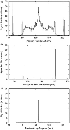
Principle component analysis is performed on the centroids of the blobs belonging to each tubular fiducial in order to find the best-fit lines (see the right side of for representative blob clusters). Blobs within 12 mm of the superior or inferior limits of the cluster are rejected, because blobs from the vertical and horizontal tubes coincide at those limits. The distance of 12 mm corresponds to 10% of the plate height of 120 mm. Furthermore, blobs at a distance of more than 2 mm from the best-fit line are excluded from the final fit in order to improve the robustness of the fit. Once the lines have been fit, the points where the vertical lines of the N cross the diagonal are computed, and their midpoint is used as a measure of the center of the plate. Next, the midpoint between the centers of the right and left plates is used as a measure of the center of the frame coordinate system. To orient the frame, the average of the direction between the centers of the right and left plates is used as the X direction of the frame. The Z direction is calculated from the vertical components of the vertical bars from the right and left plates. With the Z direction () and X direction (
), we calculate the Y direction:
these directions are then placed in a 3 × 3 matrix and orthogonalized using vtkMath::Orthogonalize3x3 from version 5.10 of the Visualization Toolkit (VTK) [Citation14].
If the anterior or posterior plates are present, then the third step (cluster selection) is repeated with an exchange of the X- and Y-axes and with the knowledge that these plates are nominally 117.5 mm fore and aft of the center. If the anterior or posterior plates are both present, then the vector between the centers of the plates is used as the Y direction of the frame, and this direction is orthogonalized together with the X and Z directions from the right and left plates. Furthermore, the center of the frame coordinate system is taken as the average of the points at the center of each plate, inversely weighted by the nominal distance of each plate from the center. When only one of the anterior or posterior plates is present, we considered ignoring the plate completely, but decided to use the vertical component of its center to adjust the frame center that had been computed from the left and right plates, after weighting it according to the plate’s nominal distance from the frame center.
The algorithm will fail if the vertical and diagonal fiducial tubes are not found in either the right or left plates. Referring to , success requires that the peaks for the vertical tubes are separated by 120 mm ± 10 mm, and that all three peaks have a width of less than 10 mm at a height of 5% of the average signal per bin.
Qualitative functional validation
Tactics was first validated with a qualitative experiment. In this experiment, as shown in , a neurosurgeon (Y.S.) planned a stereotactic biopsy using Tactics in parallel with their standard technique at the time – manual calculation of Leksell G-frame coordinates and angles using visual target localization from preoperative T1-weighted MR in clinical DICOM viewing software. Y.S. had received brief demonstrations of Tactics during development but had no first-hand experience or prior training with the tool. The target coordinates from both techniques were then compared and deemed congruent by the surgeon. The surgeon also evaluated the usability and efficiency of the software, deeming it intuitive, easy to use and apply in their workflow, and efficient compared to their experience with other software tools.
Figure 10. Initial validation of Tactics was performed through surgeons planning biopsies using Tactics alongside their standard techniques. Here, a neurosurgeon plans a target and trajectory for a brain tumor biopsy using Tactics.
Quantitative accuracy analysis
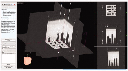
The second validation of Tactics consisted of a systematic, quantitative evaluation of system accuracy. To evaluate accuracy, we attached a stereotactic frame to a water-filled Plexiglass phantom containing a grid of fiducial markers with varied depths. We imaged the phantom using CT (512 px by 512 px by 248 px, 0.48 mm/px, 1.0 mm slice thickness, HiSpeed, General Electric Hardware, WN, USA) and the images were loaded into Tactics. A neurosurgeon performed physical localization of the fiducial markers using the attached stereotactic frame and we recorded the marker positions in the stereotactic frame coordinate system. An author (D.G.), blind to the coordinates determined using the attached stereotactic frame, targeted the fiducial markers within Tactics and recorded their determined coordinates, as shown in . We then compared the coordinates determined from both targeting techniques.
Figure 11. Targeting fiducial markers in a phantom using Tactics. The center of each circular fiducial marker was targeted by an expert and compared against known coordinates from the attached stereotactic frame. The expert was blind to the known coordinates.
Retrospective case analysis
To measure the robustness of the frame localization algorithm, and to validate the capability of Tactics as a case validation and analysis tool, we conducted a retrospective analysis of 14 stereotactic procedures performed at our institution (Z.K., K.G.) for epilepsy (n = 5), depression (n = 4), and movement disorders (n = 5) performed between January 2008 and July 2013 (). In this analysis, we measured the deviation of planned and performed stereotactic targets. Each case was recreated in Tactics by imported the cases’ original preoperative data and placing and configuring virtual leads according to the Leksell coordinates and lead specifications present within the surgical logs. We recorded the outcome of the automated frame localization algorithm and, given successful frame localization, proceeded to import and overlay postoperative images. We calculated the deviation between planned and performed placements by having two authors (K.G. and D.G.) place new virtual probes in the same position and orientation as the lead tracts appear in the postoperative data. K.G. participated in both the original procedure and the retrospective validation, while D.G., a software developer on the project, had no prior knowledge of the procedures. The authors worked together on the same probes to ensure probes were placed accurately. We recorded the tip position of both the original planned probe and the new postoperative probe and calculated the Euclidean distance between the two coordinates. This distance provided a measure of surgical variability for targeted probes, or, rather, intrinsic lead placement error during a procedure.
Table 1. Cases (n = 14) collected for retrospective analysis between planned target lead coordinates and final positions as identified in postoperative imaging and determined in Tactics.
Software development and distribution
We developed Tactics in C/C++ using open-source libraries including VTK and the Qt framework [Citation15]. Open-source libraries were chosen that would allow for rapid application development and thus rapid research use and clinical translation. We used multi-threaded algorithms when appropriate, either in standard library packages or implemented in our own libraries, to reduce the duration that the user would have to wait for results from the application. To ensure Tactics would become a unified tool used across our research project, we used portable software development tools such as CMake [Citation16] that simplify deployment on multiple platforms. Neurosurgeons assisted in the development by regularly testing Tactics and commenting on features. We performed an iterative model of software development to gather biweekly feedback from the surgeons to ensure that features of the application were useful, intuitive, and robust [Citation17–19].
We chose to open-source the application to encourage free use of the application and further development of the platform by the medical community. The source code and binaries for the application can be downloaded for free online. We encourage the community to extend the software to their specific needs, or to more procedure-specific functionality, and we present ideas for future improvement of the software as well as ideas for procedure-specific application development in Limitations and Future Work.
Results
Qualitative functional validation
Initial usability testing demonstrated that the software has matched or exceeded functionality compared to standard planning techniques and matches their target coordinates.
Quantitative accuracy analysis
Using Tactics, targets localized within the imaging phantom were measured to have a mean accuracy of 0.72 mm (SD = 0.20 mm, median = 0.71 mm) compared to positions measured with the Leksell stereotactic frame, as shown in and . No bias was observed toward any of the coordinate axes during localization or determination of total vector differences, as shown in .
Figure 12. Quantitative analysis of targeting accuracy and retrospective case validation. (a) Euclidean distance (mm) between coordinates of fiducials targeted with Tactics and coordinates measures with the Leksell G-frame; (b) localization error (distance between true frame coordinates on the imaging phantom and virtual targeting coordinates) along each Leksell G-frame coordinate axis, demonstrating statistically insignificant deviation from an expected mean of 0 mm for each axis in the sample; (c) distance between the planned and performed placements for 20 lead placements from 14 retrospective cases, demonstrating both variability in final lead placements despite careful planning and setup of the Leksell G-frame, and the capability of Tactics as a case validation and analysis tool.
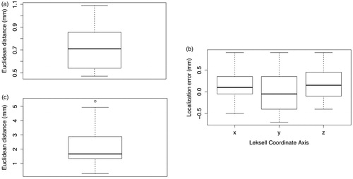
Table 2. Tactics localization error based on physical Leksell localization of fiducials in a targeting phantom compared to virtual localization of the fiducials in the imaged phantom using the software.
Retrospective case analysis
The automated frame localization algorithm succeeded for 13 of the 14 retrospective cases and failed only for one image where the left/right fiducial markers were not completely visible in the original images.
A total of 20 lead placements were examined in the 14 cases. The median Euclidean distance between the planned and performed lead placements was 1.66 mm, as shown in , demonstrating the capability of Tactics as a validation and analysis tool for stereotactic surgery.
Discussion
In this paper we have presented Tactics, a platform for planning and simulating stereotactic procedures, and have demonstrated its use in the workflow of deep-brain stimulation therapy. To ensure robust and efficient use of the software, we implemented and included automated algorithms for localization of the stereotactic frame and registration of intra- and inter-modal images.
We tested the software in three distinct stages to determine its usability and accuracy. Initial tests consisted of planning biopsies with Tactics in parallel with standard clinical tools, providing qualitative evidence that Tactics is an intuitive, efficient, and effective tool that improves on standard techniques. To measure the accuracy of the application, experts targeted fiducial markers within an imaging phantom using both Tactics and the physical stereotactic frame and compared the results. These tests demonstrated accuracy of the software within the resolution of the stereotactic frame itself, validating that the software produces accurate target coordinates.
Maciunas et al. [Citation10] provide a 0.35 mm mean targeting accuracy of the stereotactic frame and a 1.7 mm mean targeting accuracy using single-slice (1 mm thickness) CT images. Tactics, with a mean targeting accuracy of 0.72 mm, has been demonstrated to have a high degree of target accuracy. Accuracy of the software was validated using only CT images of the targeting phantom because MR images naturally contain image distortion due to the magnetic fields, which would confound the measure of error from Tactics alone. While accuracy was validated using CT images, the software is capable of finding the frame in both MR and CT images.
Our frame localization algorithm is robust to only partial visibility of the Leksell G-frame in the imaging field-of-view, requiring only the left and right fiducial plates to be present. If either or both of the anterior or posterior plates are visible, the algorithm will use the plates to improve frame localization accuracy. While robust to partial visibility, the algorithm does require at least the left and right plates. Future improvement to the algorithm could conversely require at least the anterior and posterior plates, allowing robust localization in other partial imaging scenarios.
Retrospective analysis of 14 stereotactic cases demonstrated the robustness of the automated frame localization algorithm. A limitation of this analysis is the small sample size. From our data, the algorithm failed in only one case, when one of the left or right Leksell G-frame fiducial plates was not captured in the imaging field-of-view. Correct imaging protocols must be followed for effective use of preoperative imaging in any method of stereotactic planning through both novel and standard tools. Future work should extend the validation of the frame localization algorithm to larger volumes of real clinical data. The retrospective analysis also demonstrated the capability of Tactics to be used as a case validation and analysis tool.
Tactics is simple and robust; it provides an intuitive representation of the stereotactic domain, allowing surgeons to easily envision their surgical plans. Electrode insertions can be simulated using the included base (or user-extended) models of implantable electrodes and thus individual contacts of each electrode can be accurately placed to greatest effect. The lead catalog can be easily extended to include leads available to the users of the software.
Current related works trend to the development of systems that guide surgeons in the development of their plans. We have developed Tactics as a platform for generic stereotactic procedures, and not as a tool for a specific application of stereotaxy, and thus determined that introducing application-specific planning assistance would exceed its intended replacement of standard tools for our study. Because the software is open-source, users may develop, introduce, and share application-specific guidance tools built on-top of the software.
Limitations and future work
We have designed Tactics as a platform for stereotactic procedures and not as an application tailored to advanced logistics within a specific application of stereotaxy. Therefore, Tactics, in its current state, is limited to assisting surgeons in expressing their clinical expertise for planning stereotactic operations and provides intuitive visualization and simulation of these plans. Tactics does not, at the moment, assist in the determination of the plan to be performed. Related works in computer-assisted DBS have attempted to address this component through the use of functional databases and electrophysiological atlases and maps [Citation4,Citation6,Citation20]. Future extensions of the Tactics platform to DBS may include similar components to further assist surgeons in creating their plans. Currently, we plan to include tractography, or the segmentation of neural tracts from acquired diffusion tensor imaging, as an additional optional overlay for visualization, as several studies have shown the relevance of tractography in improved clinical outcomes for DBS [Citation21].
Lead specifications
While effective and efficient in its simplicity, the lead specification format makes assumptions that may limit the applicability of this format to novel lead designs such as segmented leads [Citation22–24]. The extension of the specification to a more complete format that would allow for more complex leads is a desirable direction for future improvement.
Frame localization
Tactics is tightly coupled to the localization of the Leksell G-frame. This was a pragmatic choice given the use of the frame in our institution, though extending Tactics to localize different frames is an important area of future work. This extension was considered in the original implementation of the software. From a software architecture and design perspective, the application codes against a generic frame localization interface, which could have any number of implementations against other frames that could be swapped out in the code or chosen at runtime.
Handling of multiple volumes
The capability of Tactics to only import two volumes is a limitation and a high-priority area for improvement; Tactics should be expanded to allow for any number of volumes, where the user may declare their registration relationships. This would allow for several use-cases, including the ability to plan lead placements prior to the acquisition of images containing the stereotactic frame, and the construction of typical procedure templates, where standard lead placements are defined against an atlas which can then be registered to the patient’s volumes, allowing for fine-tuning and personalized care. Such advancements could improve the workflow efficiency of such stereotactic procedures.
Systematic comparison to related work
While we have quantitatively demonstrated accuracy within the measurement resolution of the physical Leksell G-frame, a systematic comparison of Tactics – in terms of accuracy, processing performance, planning efficiency, and other metrics – to other noncommercial and commercial offerings in the field would be a valuable follow-up study.
Conclusions
Tactics demonstrates a unified workflow for clinical and research stereotactic procedures, from the initial stages of planning through to the final stages of postoperative trajectory evaluations. The software has become an integral tool for clinicians within our hospital and our research team, having been used internally to plan over 300 depth-electrode targets and trajectories in over 50 surgical cases, and to plan dozens of stereotactic biopsies.
Given experimental validation of the accuracy of the application and the enthusiastic adoption of the tool among our team’s clinicians and researchers, Tactics has proven to be robust, intuitive, and an asset to stereotactic workflows.
As Tactics is open-source and free to download and modify, community contributions have the ability to extend the platform for a variety of different stereotactic applications. Source code for Tactics is located online at https://github.com/atamai/tactics.
Disclosure statement
No potential conflict of interest was reported by the author(s).
Additional information
Funding
References
- Galloway RL, Maciunas RJ. Stereotactic neurosurgery. Crit Rev Biomed Eng. 1990;18:181–205.
- Hemm S, Wårdell K. Stereotactic implantation of deep brain stimulation electrodes: a review of technical systems, methods and emerging tools. Med Biol Eng Comput. 2010;48(7):611–624.
- Perlmutter JS, Mink JW. Deep brain stimulation. Annu Rev Neurosci. 2006;29(1):229–257.
- D’Haese P-F, Pallavaram S, Li R, et al. CranialVault and its CRAVE tools: a clinical computer assistance system for deep brain stimulation (DBS) therapy. Med Image Anal. 2012;16(3):744–753.
- Mayberg HS, Lozano AM, Voon V, et al. Deep brain stimulation for treatment-resistant depression. Neuron. 2005;45(5):651–660.
- D’Albis T, Haegelen C, Essert C, et al. PyDBS: an automated image processing workflow for deep brain stimulation surgery. Int J Comput Assist Radiol Surg. 2014;10(2):2–16.
- Tisch S, Zrinzo L, Limousin P, et al. Effect of electrode contact location on clinical efficacy of pallidal deep brain stimulation in primary generalised dystonia. J Neurol Neurosurg Psychiatry. 2007;78(12):1314–1319.
- Sun HP, Jung HH, Lee JY, et al. Electrode position determined by fused images of preoperative and postoperative magnetic resonance imaging and surgical outcome after subthalamic nucleus deep brain stimulation. Neurosurgery. 2008;63(5):925–936.
- Papavassiliou E, Rau G, Heath S, et al. Thalamic deep brain stimulation for essential tremor: relation of lead location to outcome. Neurosurgery. 2004;54(5):1120–1130.
- Maciunas RJ, Galloway RL, Latimer JW. The application accuracy of stereotactic frames. Neurosurgery. 1994;35(4):682–695.
- Smith SM. Fast robust automated brain extraction. Hum Brain Mapp. 2002;17(3):143–155.
- Mattes D, Haynor DR, Vesselle H, et al. PET-CT image registration in the chest using free-form deformations. IEEE Trans Med Imaging. 2003;22(1):120–128.
- Studholme C, Hill DLG, Hawkes DJ. An overlap invariant entropy measure of 3D medical image alignment. Pattern Recognit. 1999;32(1):71–86.
- Schroeder WJ, Martin KM. The visualization toolkit: an object-oriented approach to 3D graphics. 2006. [cited 2020 Apr 29]. Available from: http://www.kitware.com/products/books/VTKTextbook.pdf
- Qt [Internet]. Cross-platform application & UI development framework. Helsinki (Finland): Qt; 2020. Available from: http://www.qt.io/
- CMake [Internet]. Clifton Park (NY): Kitware, Inc.; 2020. Available from: http://www.cmake.org/
- Mitchell SM, Seaman CB. A comparison of software cost, duration, and quality for waterfall vs. iterative and incremental development: A systematic review. Paper presented at Third International Symposium on Empirical Software Engineering and Measurement; 2009, October 15–16, Lake Buena Vista, FL; p. 511–515.
- Ebert C, Abrahamsson P, Oza N. Lean software development. IEEE Softw. 2012;29(5):22–25.
- Mirnalini K, Raya VR. Agile – A software development approach for quality software. Paper presented at International Conference on Educational and Information Technology; 2010, September 17–19, Chongqing, China.
- Guo T, Finnis KW, Parrent AG, et al. Visualization and navigation system development and application for stereotactic deep-brain neurosurgeries. Comput Aided Surg. 2006;11(5):231–239.
- Riva-Posse P, Choi KS, Holtzheimer PE, et al. Defining critical white matter pathways mediating successful subcallosal cingulate deep brain stimulation for treatment-resistant depression. Biol Psychiatry. 2014;76(12):963–969.
- Martens HCF, Toader E, Decré MMJ, et al. Spatial steering of deep brain stimulation volumes using a novel lead design. Clin Neurophysiol. 2011;122(3):556–558.
- Toader E, Decré MMJ, Martens H. Steering deep brain stimulation fields using a high resolution electrode array. Paper presented at the 2010 Annual International Conference of the IEEE Engineering in Medicine and Biology Society; 2010, 31 August to September 4, Buenos Aires, Argentina.
- Buhlmann J, Hofmann L, Tass PA, et al. Modeling of a segmented electrode for desynchronizing deep brain stimulation. Front Neuroeng. 2011;4. DOI:10.3389/fneng.2011.00015