
 ?Mathematical formulae have been encoded as MathML and are displayed in this HTML version using MathJax in order to improve their display. Uncheck the box to turn MathJax off. This feature requires Javascript. Click on a formula to zoom.
Abstract
In traditional orthognathic surgery, the dental splint technique is typically used to assist surgeons to reposition the maxilla or mandible. However, the design and manufacturing of dental splints is time-consuming and labor-intensive, and the templates may not applicable for some complicated cases due to the anatomic intricacies in the maxillofacial region. During recent years, computer-aided navigation technology has been widely used in oral and maxillofacial surgery. However, due to the limitation of current calibration and registration methods, it has been rarely reported for the motion tracking of intraoperative reposition for the loosed bone graft. In this study, a novel surgical navigation system was developed. With the use of this system, not only the surgical saw can be tracked in real-time, but also the loosed bone graft can be navigated under the guidance of the interactive 2D and 3D views until it is aligned with the preoperatively planned position. The phantom experiments validated the feasibility of our surgical navigation system, and the mean error of image-guided reposition was 1.03 ± 0.10 mm, which was significantly more accurate than the mean error of 5.57 ± 1.40 mm based on the non-navigated methods.
Introduction
In traditional orthognathic surgery, the dental splint technique is typically used to assist the surgeon to reposition the maxilla or mandibular. However, the design and manufacturing of dental splints are time-consuming and labor-intensive, the technique learning curve is steep [Citation1]. Furthermore, even the usage of the surgical splints, the intraoperative procedures may cause errors due to the variable anatomy and limited operative space in the maxillofacial region. The actual maxillomandibular reposition may not be identical to the planned position.
Over the past decades, owing to the rapid development of computer imaging technologies, the image-guided surgical navigation system has been increasingly applied for various kinds of surgical specialties, including oral implantology [Citation2], total knee arthroplasty [Citation3], orthopedics [Citation4], spinal surgery [Citation5], and oral and maxillofacial surgery [Citation6,Citation7]. With the use of the navigation system, the surgical instruments are tracked in real-time, and their orientations and positions in relation to the anatomical structures are displayed on the computer screen. As a result, the surgeons can perform the surgery precisely according to the preoperative planning.
The current commercially available surgical navigation systems such as BrainLab (Brainlab AG, Feldkirchen, Germany), Stryker (Stryker®, Kalamazoo, USA), and StealthStation (Medtronic, Minneapolis, USA) have proven successful in the clinical applications for minimizing the risks of the surgery. In addition, several groups have proposed the application of a navigation system in orthognathic surgery. For example, Choi et al. proposed a stereoscopic optical tracking system to track the maxilla [Citation8]. Naujokat et al. proposed a noninvasive mandible registration technique in navigation-assisted orthognathic surgery [Citation9]. However, since the conventional calibration method is not applicable for the patient-specific loosed bone graft with various shapes after osteotomy, the intra-operative motion tracking of the maxillomandibular complex is not realized in these systems. Furthermore, due to their source codes not open to the public, the lack of software expandability is obvious and the surgeons’ individual requirements cannot be met.
In this study, a novel real-time image-guided reposition system for the loosed bone graft in orthognathic surgery was developed, aiming at improving the precision and safety of the surgery. Phantom experiments were performed to evaluate the accuracy of positioning of maxillomandibular complex, and the results were compared to the non-navigated (free-hand operation) reposition.
Materials and methods
The workflow of the image-guided system for orthognathic surgery is described as follows [Citation10]:
Preoperative planning. The DICOM image data (typically computed tomography (CT) images) data are imported to the navigation system and displayed on the computer screen, which encompasses 2D images and 3D-reconstructed models. The preoperative surgical planning is performed to segment the maxilla and mandible, and to design the drilling and osteotomy trajectories, and then the loosed bone graft is virtually moved to the ideal position.
Calibration of the surgical instruments and loosed bone graft. The calibration procedure is required to determine the spatial relationship between the surgical instrument and the reference frame before real-time motion tracking. On the basis of this relationship, the movements of the surgical tool can be represented through those of the reference frames. In general, the tip point of the instrument, the axis of the drill, and the surface of the saw are calibrated using a calibration tool.
Registration. For all image-guided systems, an essential component is the registration (alignment) of the patient’s position in relation to the image data set. In the image-guided surgical navigation system, point-based registration is the most commonly used approach. In this method, anatomic points or artificial fiducial landmarks from the patient are matched to corresponding points in the preoperative images.
Real-time navigation. After patient to image registration, the surgical tools and loosed bone grafts are tracked in real-time, and their positions and orientations are rendered on both the 2D and 3D views. As a result, the surgeon can accomplish the operation according to the preoperative planning under the interactive guidance of the navigation system.
Calibration of surgical instruments and loosed bone graft
respectively show a surgical drill and saw, and the coordinate systems for the instrument and the reference frame are respectively established. The calibration encompasses three sections, that is, ‘Pivot Calibration’, ‘Axis Calibration of surgical drill’ and ‘Surface Calibration of surgical saw’.
Figure 1. (a) The coordinate systems of the surgical drill and the reference. (b) The coordinate systems of the surgical saw and the reference. (c) The calibration for the normal and axis of surgical saw.
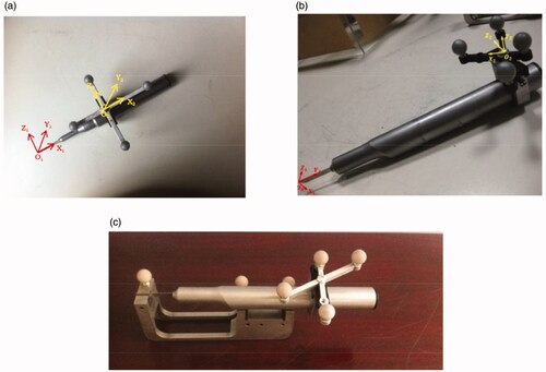
With respect to the ‘Pivot Calibration’, for the detailed description of the involved algorithms during this procedure, please refer to Jaramaz et al. [Citation11]. As for the ‘Axis Calibration of surgical drill’, the surgical drill is inserted into the matched axial hole in a calibration tool, and the direction vector (u, v, w) of surgical drill relative to the coordinate system of reference frame can be obtained with the support of the tracking device. According to EquationEquation (1)(1)
(1) , T1 and T2 are, respectively, the translation matrices of the surgical drill’s reference frame and calibration tool relative to the tracking system, and (1,0,0)T is the direction vector of the axial hole in the coordinate system of calibration tool.
(1)
(1)
As for the ‘Surface Calibration of surgical saw’ [Citation12], shows the calibration procedure. The handpiece of the saw lies on the two V-shaped grooves, and the blade is inserted into the slot of the calibration tool. The axial vector of the V-shaped groove and normal vector of the slot under the coordinate system of the calibration tool are all known, and with the support of the tracking device, the normal vector T and axial-vector
T of surgical saw relative to the reference frame can be calculated as follows:
(2)
(2)
(3)
(3)
According to EquationEquations (2)(2)
(2) and Equation(3)
(3)
(3) , T1 and T2 are, respectively, the translation matrices of the surgical saw’s reference frame and calibration tool relative to the tracking system. (1,0,0)T and (0,1,0)T are, respectively, the normal vector of slot and axial-vector of v groove in the coordinate system of calibration tool.
Since the calibration tool is not suitable for the loosed bone graft with a variety of shapes, the calibration transformation matrix can be calculated through a point-based (or combined with surface matching) registration method. The details are illustrated in and described as follows:
Figure 2. The calibration of the loosed bone graft, and the registration of the whole surgical navigation system.
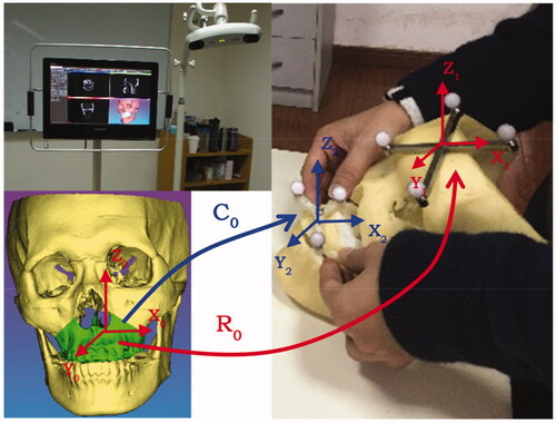
First of all, the coordinates of fiducial landmarks (such as the mini Titanium screws and anatomic landmarks on the loosed maxilla or mandible) under VCS-X0Y0Z0 (virtual coordinate system, also referred to as the image coordinate system) are acquired through indicating in the 2D/3D interactive environment. Meanwhile, the corresponding coordinates of these fiducial landmarks under RCS- X2Y2Z2 (also referred to as the reference frame coordinate system of the loosed bone graft) can be obtained using the positioning probe to localize each landmark. Then, according to the singular value decomposition (SVD) algorithm [Citation13], the calibration transformation matrix C0 can be calculated through these two paired lists of fiducial points. In addition, if the accuracy of point-based calibration is not precise enough (for example, there may be minor manual errors in locating the anatomical landmarks), the following surface-based registration is adopted for the improvement of calibration: the point cloud is collected on the surface of the loosed bone graft using the positioning probe, and the coordinates of each point under RCS-X2Y2Z2 are computed. Then, on the basis of this point cloud and corresponding ‘.stl’ model of the loosed bone graft, the C0 can be improved through the iterative closest point (ICP) algorithm [Citation14]. As for the registration of the whole surgical navigation system, a similar method is adopted to compute the spatial transformation matrix of R0 between RCS-X1Y1Z1 (also referred to as the reference frame coordinate system of the patient) and VCS-X0Y0Z0.
On the basis of the above-mentioned methods, the function module of the loosed bone graft calibration is programmed using well-known open-sourced toolkits such as the VTK, CTK, ITK, IGSTK and QT, and integrated into our self-developed surgical navigation software.
Phantom experiment
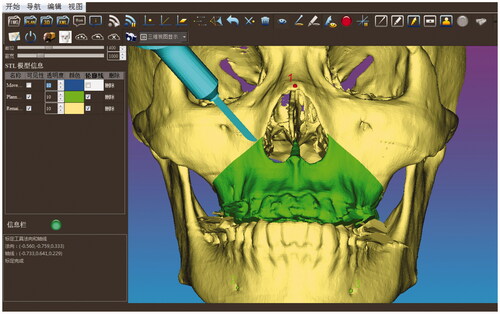
The phantom experiments were conducted to validate the feasibility of our real-time image-guided system. The infrared tracking device (Polaris Vicra, NDI Inc., Canada) and the all-in-one computer (IntelCorei7 processor, 8GB RAM, and an AMD Radeon HD 7650 A graphics card) were used to run the navigation system (shown in the left upper image of ). Firstly, on the basis of CT-scanned data, the image segmentation and 3D -reconstruction of the craniomaxillofacial skeleton was performed. The preoperative surgical planning including the design of the osteotomy trajectory and the maxilla reposition was determined in our software. Then, after the planning data were saved and imported to the navigation system, the calibration of the positioning probe and the surgical saw was conducted subsequently through the calibration tool. On the basis of the anatomical landmark pairs, an initial registration transformation matrix was obtained. However, since the identification of the bone and teeth landmarks was not accurate enough, the point cloud of the craniomaxillofacial skeleton model was then collected through the positioning probe for further surface matching registration aiming at precision improvement. Finally, the position and orientation of the saw were tracked in real-time and displayed on both the 2D and 3D views. shows that the maxilla was resected according to the preoperatively planned trajectory.
Figure 3. The position and orientation of the surgical saw were tracked in real time and displayed on the computer screen so that the maxilla was resected according to the preoperative planned trajectory.
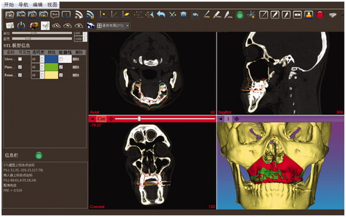
Once the osteotomy had been accomplished, the loosed maxilla was calibrated through the pair-point registration method based on the cusp of the bilateral canines and the buccal cusp of the bilateral premolars. However, if anatomic landmarks are used as fiducial points for the purpose of non-invasion, the registration error will be large since they cannot be located precisely, and it can only be used as the initial registration and then surface registration is furtherly used to improve the accuracy. As a result, the loosed bone graft can be intraoperatively tracked and repositioned carefully according to the preoperatively planned position under the interactive guidance of 2D and 3D image rendering environment (shown in ). The red and green contours in the 2D views respectively represent the positions of the intraoperative tracked and the preoperative planned loosed maxilla. The red and green models in the 3D view respectively represent the intraoperative tracked and the preoperative planned loosed maxilla.
Figure 4. The reposition of the loosed maxilla under the interactive guidance of 2D and 3D image rendering environment. The red and green contours in the 2D views respectively represent the positions of the intraoperative tracked and the preoperative planned loosed maxilla. The red and green models in the 3D view, respectively, represent the intraoperative tracked and the preoperative planned loosed maxilla.
Results
Accuracy verification
In terms of accuracy, the comparison of the loosed bone graft repositioning with and without navigated guidance was performed. The freehand repositioning was conducted by intraoperative measurements, and the loosed bone graft was determined by trial and error [Citation15]. Both the non-navigated (free-hand operation) and image-guided reposition operation were repeated ten times on the same phantom respectively, and each intraoperative repositioned bone model was saved as a file in ‘.stl’ format and exported to specific self-developed software for comparing with the preoperative plan through the graphical post-processing. The color maps are shown in are, respectively, the error distribution of non-navigated (free-hand operation) and image-guided maxilla reposition after the guided osteotomy.
Figure 5. The error distribution of the loosed maxilla reposition. (a) Non-navigated (free-hand operation) reposition. (b) Image-guided reposition.
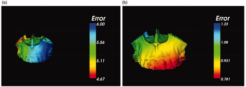
In addition, shows two groups of distance errors through different repositioning ways. According to the ten repeats in Group 1, the maximum, minimum and mean distance errors of homologous points on the preoperative planned and the non-navigated (free-hand operation) reposition models were 6.12 mm, 4.33 mm and 5.57 ± 1.40 mm respectively. As for Group 2, the maximum, minimum and mean distance errors of homologous points on the preoperative planned and the image-guided reposition models were 1.31 mm, 0.55 mm and 1.03 ± 0.10 mm respectively. Therefore, the accuracy of real-time image-guided reposition for the loosed bone graft was significantly improved more than five times than non-navigated (free-hand) operation.
Table 1. Group 1: The distance error of homologous points on the preoperative planned and the non-navigated (free-hand operation) reposition models. Group 2: The distance error of homologous points on the preoperative planned and the image-guided reposition models.
Discussion and conclusion
As for the bimaxillary orthognathic surgery, although the surgical splint technique is typically used to reposition the maxilla intraoperatively, the limitations are obvious. For example, it is time-consuming requiring a great deal of laboratory work since the surgical splint is usually manufactured based on the traditional model surgery. Furthermore, it has a quite high level of imprecision due to the errors caused during the procedures such as bite registration, facebow registration, transferring the facebow to the articulator, and measurement of the movement of the plaster cast [Citation16,Citation17]. Secondly, even if the splint now can be fabricated through the computer-aided design and manufacturing (CAD/CAM) technologies for improving the accuracy in the conventional model process [Citation18,Citation19], the intermediate splint placed on the instability of the mandible may directly interfere with the placement of the maxilla in the desired position [Citation20]. The average time for preparation of occlusal splints is less than an hour. However, our surgical navigation system can avoid the usage of occlusal splints, and the average time consumption for the registration and calibration is around 10 min.
In recent years, computer-aided surgical planning has been widely used in the field of craniomaxillofacial surgery [Citation21]. With the support of the three-dimensional (3D) analysis and surgical planning, the more accurate treatment planning can be created and the less surgical preparation time can be achieved. For example, Centenero et al. described the advantages of 3D virtual planning in predicting postoperative results and manufacturing surgical splints with the use of the software program Simplant® Pro OMS 10.1 (Materialise®, Leuven, Belgium) [Citation22]. Sun et al. presented a technical note of 3D virtual model surgery for the intermediate splint fabrication in bimaxillary orthognathic surgery [Citation23]. But, this new method only replaced conventional model surgery, and the errors involved in the fabricating process still persisted. Although Yu et al. developed a ‘single-splint’ technique with intraoperative adjustments and checkpoints aiming at improving the accuracy of the surgery, the surgery was still required to design and manufacture the splint [Citation24]. Thus, as mentioned above, it still poses a significant challenge to transfer the preoperative planning to the anatomically complex operation site accurately.
Compared with the technology of occlusal splints, the advantage of surgical navigation is its real-time tracking and rendering of the free maxillary bone segment, which is more visually vivid for surgeons [Citation25]. During the reposition, the relative position between the preoperative planned and the real loosed bone grafts can be vividly shown on the screen in real-time. However, since the current calibration methods are not suitable for the loosed bone graft, the navigation system with motion tracking of bone for the intraoperative reposition is seldom employed in orthognathic surgery [Citation26]. Although Li et al. presented a surgical navigation system for orthognathic surgery allowing the optical tracking guided free-hand repositioning of the maxillomandibular complex, the important issues pertaining to the calibration of the surgical instruments and the loosed bone graft were not clarified [Citation1].
Therefore, in this study, a novel calibration method for loosed bone graft was proposed, and a real-time image-guided reposition system for the orthognathic surgery was developed. With the use of this system, the surgical saw can be tracked in real-time and rendered on the computer screen so that the surgeon can transfer the preoperative surgical planning to the real operation site. In addition, after the osteotomy, the intraoperative reposition of the loosed bone graft can be navigated under the guidance of the interactive 2D and 3D views until it is aligned with the preoperatively planned position. According to the accuracy verification results, the maximum, minimum and mean errors of image-guided reposition can be improved to 1.31 mm, 0.55 mm and 1.03 ± 0.10 mm respectively, while they are 6.12 mm, 4.33 mm and 5.57 ± 1.40 mm of non-navigated (free-hand operation) reposition. It demonstrates that the navigation system can effectively improve the reposition precision. In addition, we compared the precision of navigation technology with the usage of occlusal splints. For example, Schouman et al. carried out experiments on the accuracy of splints in orthognathic surgery [Citation27]. In his study, the average translation differences between the preoperative planed and postoperative images in mediolateral, anteroposterior and superoinferior direction were 1.55 mm, 2.17 mm and 0.81 mm, respectively. In our study, the mean distance errors of homologous points on the preoperative planned and the image-guided reposition models were 1.03 ± 0.10 mm. Under the condition that the measured error obeys the normal distribution, the lower and upper limits of distance error are respectively 1.00 mm and 1.06 mm with 95% confidence intervals. It means that our navigation system is comparable to occlusal splints, fulfilling the clinical precision requirements.
Nevertheless, this is a pilot study and there is still further work to be done in future research and exploration. For example, in actual operation, a tooth-supported registration template will be used to serve for registration and tracking the free maxillary bone segment. On this registration template, a small rigid bracket is attached, in which the markers (the infrared light-reflective balls) can be installed, and several titanium screws can be inserted as registration fiducial landmarks. Actually, this kind of surgical template has already been used for our dental implant placement surgical navigation system [Citation2], and some other articles report similar ideas [Citation28–30]. For example, in Marmulla and Niederdellmann’s study [Citation30], two DRFs are attached to a laboratory model before surgery, and the transform matrix between the bone segment and its DRF is calculated on the model. Then, the DRF on the bone segment is transferred from the model to the patient by a splint, therefore the relationship between the DRF and the bone segment is not changed. In our study, two DRFs are attached to the patient directly, and the relationship between the bone segment and its DRF is determined through registration and calibration during the surgery. In addition, some clinical trials will be conducted in the near future to validate the reliability of our system. Besides, the usage of the surgical navigation system is a little bit more complicated than the surgical guides. Therefore, before using the repositioning system for real surgery, the surgeon is required to be trained in order to improve their proficiency, and the surgeon’s proficiency in this system and fatigue during surgery may affect the accuracy in practical application.
Disclosure statement
No potential conflict of interest was reported by the author(s).
Additional information
Funding
References
- Li B, Zhang L, Sun H, et al. A new method of surgical navigation for orthognathic surgery: optical tracking guided free-hand repositioning of the maxillomandibular complex. J Craniofac Surg. 2014;25(2):406–411.
- Chen X, Ye M, Lin Y, et al. Image guided oral implantology and its application in the placement of zygoma implants. Comput Methods Programs Biomed. 2009;93:162–173.
- Inui H, Taketomi S, Takei S, et al. Influence of navigation system updates on total knee arthroplasty. Sports Sci Med Rehab. 2013;5:10–18.
- Behrendt D, Mutze M, Steinke H, et al. Evaluation of 2D and 3D navigation for iliosacral screw fixation. Int J Cars. 2012;7(2):249–255.
- Jentzsch T, Sprengel K, Peterer L, et al. 3D navigation of endoscopic rhizotomy at the lumbar spine. J Clin Neurosci. 2016;23:101–105.
- Gui H, Yang H, Shen SG, et al. Image-guided surgical navigation for removal of foreign bodies in the deep maxillofacial region. J Oral Maxillofac Surg. 2013;71(9):1563–1571.
- Sun Y, Luebbers HT, Agbaje JO, et al. The accuracy of image-guided navigation for maxillary positioning in bimaxillary surgery. J Craniofac Surg. 2014;25(3):1095–1099.
- Choi JW, Jang J, Jeon K, et al. Three-dimensional measurement and registration accuracy of a third-generation optical tracking system for navigational maxillary orthognathic surgery. Oral Surg Oral Med Oral Pathol Oral Radiol. 2019;128(3):213–219.
- Naujokat H, Rohnen M, Lichtenstein J, et al. Computer-assisted orthognathic surgery: evaluation of mandible registration accuracy and report of the first clinical cases of navigated sagittal split ramus osteotomy. Int J Oral Maxillofac Surg. 2017;46(10):1291–1297.
- Cleary K, Peters TM. Image-guided interventions: technology review and clinical applications. Annu Rev Biomed Eng. 2010;12:119–142.
- Jaramaz B, Nikou C, Simon DA, et al. Range of motion after total hip arthroplasty: experimental verification of the analytical simulator. Paper presented at the International Conference on Computer Vision, Virtual Reality, and Robotics in Medicine; 1997 April 3–6; Nice, France.
- Zeiss M, Blau A, Birkenbach R, et al. inventors; Brainlab AG, assignee. Navigation-calibrating rotationally asymmetrical medical instruments or implants: U.S. Patent 7213598. 2007 August 5.
- Arun KS, Huang TS, Blostein SD. Least-squares fitting of two 3-D point set. IEEE Trans Pattern Anal Mach Intell. 1987;9:698–700.
- Besl PJ, Mckay ND. A method for registration of 3-D shapes. IEEE Trans Pattern Anal Mach Intell. 1992;14(2):239–256.
- Pascal E, Majoufre C, Bondaz M, et al. Current status of surgical planning and transfer methods in orthognathic surgery. J Stomatol Oral Maxillofac Surg. 2018;119(3):245–248.
- Mazzoni S, Badiali G, Lancellotti L, et al. Simulation-guided navigation: a new approach to improve intraoperative three-dimensional reproducibility during orthognathic surgery. J Craniofac Surg. 2010;21(6):1698–1705.
- Sun Y, Luebbers HT, Agbaje JO, et al. Accuracy of upper jaw positioning with intermediate splint fabrication after virtual planning in bimaxillary orthognathic surgery. J Craniofac Surg. 2013;24(6):1871–1876.
- Hatamleh M, Turner C, Bhamrah G, et al. Improved virtual planning for bimaxillary orthognathic surgery. J Craniofac Surg. 2016;27(6):e568–e573.
- Hatamleh MM, Bhamrah G, Ryba F, et al. Simultaneous computer-aided design/computer-aided manufacture bimaxillary orthognathic surgery and mandibular reconstruction using selective-laser sintered titanium implant. J Craniofac Surg. 2016;27(7):1810–1814.
- Li B, Zhang L, Sun H, et al. A novel method of computer aided orthognathic surgery using individual CAD/CAM templates: a combination of osteotomy and repositioning guides. Br J Oral Maxillofac Surg. 2013;51(8):e239–e244.
- Steinbacher DM. Three-dimensional analysis and surgical planning in craniomaxillofacial surgery. J Oral Maxillofac Surg. 2015;73:40–56.
- Centenero SA, Hernandez-Alfaro F. 3D planning in orthognathic surgery: CAD/CAM surgical splints and prediction of the soft and hard tissues results – our experience in 16 cases. J Cranio-Maxillo-Facial Surg. 2012;40:162–168.
- Sun Y, Luebbers H, Politis C. Three-dimensional virtual model surgery to fabricate the digital intermediate splint. J Craniofac Surg. 2013;24(2):563–565.
- Yu C, Bergeron L, Lin C, et al. Single-splint technique in orthognathic surgery: intraoperative checkpoints to control facial symmetry. Plast Reconstr Surg. 2009;124(3):879–886.
- Juergens P, Kim H, Kunz C, et al. Intraoperative three-dimensional real-time navigation in orthognathic surgery. Int J Oral Maxillofac Surg. 2009;38(5):474.
- Lin H, Lo L. Three-dimensional computer-assisted surgical simulation and intraoperative navigation in orthognathic surgery: a literature review. J Formos Med Assoc. 2015;114(4):300–307.
- Schouman T, Rouch P, Imholz B, et al. Accuracy evaluation of CAD/CAM generated splints in orthognathic surgery: a cadaveric study. Head Face Med. 2015;11:24.
- Lin WS, Yang CC, Polido WD, et al. Cad-cam cobalt-chromium surgical template for static computer-aided implant surgery: a dental technique. J Prosthet Dent. 2020;123(1):42–44.
- Sun Y, Ding Q, Tang L, et al. Accuracy of a chairside fused deposition modeling 3D-printed single-tooth surgical template for implant placement: an in vitro comparison with a light cured template. J Craniomaxillofac Surg. 2019;47(8):1216–1221.
- Marmulla R, Niederdellmann H. Computer-assisted bone segment navigation. J Craniomaxillofac Surg. 1998;26(6):347–359.