
Abstract
Over the past decade, minimally invasive sacroiliac joint (SIJ) fusion has become an effective treatment for patients suffering from low back pain (LBP) originating from the SIJ. Perioperative C-arm fluoroscopy-assisted surgical navigation during SIJ fusion remains challenging due to the lack of 3D spatial information. This study developed and assessed a 3D CT/2D fluoroscopy integration approach based on digitally reconstructed radiographs (DRRs) obtained from pre-operative CT scans. Development of this approach proved feasible and landmarks were successfully translated, in retrospect, to perioperatively acquired fluoroscopies. Further expansion of and research into the proposed approach to increase perioperative navigation is indicated and additional validation should be performed.
1. Introduction
The sacroiliac joint (SIJ) is a frequent but under-recognized and under-diagnosed origin of low back pain (LBP), mainly due to the absence of any gold standard diagnostic test. Varying prevalence of SIJ pain has been described in recent literature, illustrating that in approximately 15–30% of all patients suffering from LBP below L5, pain originates from the SIJ [Citation1–4]. Once SIJ dysfunction is identified as origin of LBP and non-surgical therapies (e.g. physical therapy or therapeutic SIJ injections) fail to provide sustained symptom relief, SIJ fusion (SIJF) may be indicated [Citation5,Citation6]. Over the past decade, minimally invasive SIJF has become the surgical approach of choice, showing promising results [Citation7–10]. Minimally invasive SIJF by implantation of three triangular titanium fusion implants (iFuse system, SI-BONE, Inc., San Jose, CA) assisted by C-arm fluoroscopy has shown improvements in patient-reported outcomes and provide superior outcome results in comparison to conservative treatment or screw-type and open surgery [Citation11–13]. During SIJF surgery, it is crucial that implantation trajectory and final implant position avoid the L5 nerve root located on the anterior sacral alar surface and the S1 and S2 neural foramen to reduce the chance of major complications. Therefore, accurate perioperative navigation is of high importance.
Perioperative 2D C-arm fluoroscopy imaging is currently employed to guide implant placement. Due to the single plane-projection of 2D fluoroscopy, there is a lack of 3D spatial information during surgery, making spatial orientation, identification of 3D-oriented landmarks and implant path planning during SIJ fusion complicated. Therefore, there is a need to enhance perioperative fluoroscopy-based navigation and landmark detection.
Integration of pre-operative CT and perioperative fluoroscopy imaging might provide valuable supporting information during SIJ fusion surgery in landmark detection and implant placement. A frequently applied 3D CT/2D fluoroscopy integration approach is based on image registration of simulated fluoroscopy images from CT data called digitally reconstructed radiographs (DRRs) [Citation14,Citation15]. DRR generation is an image processing technique that computes simulated 2D radiographs from 3D CT datasets using ray casting through the 3D CT volume [Citation16]. DRRs have dimensional agreement with fluoroscopy imaging (2D vs. 2D) and, therefore, might allow for image registration, i.e. the process of transferring two images into the same reference/coordinate frame [Citation14]. Additional to registration of CT data and fluoroscopy imaging, segmentations of landmark structures within the CT scans can be incorporated on the DRRs, which might further enhance perioperative navigation. Therefore, this study proposes a pre-operative 3D CT and perioperative 2D fluoroscopy integration approach with the aim of improving perioperative landmark detection and navigation during SIJ fusion surgery.
2. Materials and methods
2.1. Data collection
Anonymized pre- and post-operative CT and perioperative fluoroscopy imaging data from one patient that underwent SIJ fusion at Isala Hospital (Zwolle, the Netherlands) was retrospectively obtained. A declaration of a non-interventional study was obtained at the Medical Ethics Review Committee (METC) Isala to collect the data (registration number 200117). The CT scans were acquired using a Philips iCT 256 CT scanner (Philips Healthcare, Best, Netherlands) while the patient was lying supine. Scanning parameters were 140 kVp, 1.0-mm slice thickness, 0.5-mm increment, 0.925 pitch and a 512 × 512 image matrix. Fluoroscopy images were obtained using a GE Healthcare OEC FluoroStar (GE Healthcare, Chicago, IL) with the patient in prone position.
Manual segmentations of the S1 and S2 neural foramen were made on the pre-operative CT scan in ITK-SNAP [Citation17]. All imaging processing steps were implemented in MATLAB (R2019b, The MathWorks Inc., Natick, MA).
2.2. Image processing workflow
During SIJ fusion surgery, initial lateral fluoroscopy alignment is obtained based on superimposing visible sacral bone contours. To acquire CT-based DRRs that accurately compare to the aligned fluoroscopy images, lateral alignment of the CT data should be achieved. Therefore, an initial explorative workflow was developed which aimed to identify the spatial relation between visible fluoroscopy lines and structures on the CT scan that correspond to these lines. The following steps were taken:
Pre-operative CT scans were loaded into MATLAB and the sagittal slices were shown in an interactive viewer that allowed for simple browsing through the slices.
Multiple cortical bone structures were delineated manually by the main researcher on different sagittal slices, e.g. the anterior alar wall, the anterior border of the ilium lateral to the SIJ and the promontory.
A laterally oriented DRR was generated based on the CT data that incorporated the delineated structures. The resulting DRRs were visually assessed to determine which highlighted structures relate to which visible lines on the fluoroscopy.
The following image processing steps were performed to obtain DRRs with spatial correspondence to perioperative fluoroscopy images:
Pre-operative CT scans were thresholded to remove soft tissue components. The threshold level was selected using an interactive threshold selection tool after which all voxels with values lower than the threshold were set to zero (black).
Realignment based on the previously identified spatial relation between CT and fluoroscopy was performed. The left and right anterior alar surface was selected on the axial slice on which the promontory was located. The spatial transformation that aligned both reference points horizontally was calculated and applied to the CT matrix automatically to ensure lateral alignment. The process was repeated on a coronal slice to perform anterior alignment.
The thresholded and realigned CT data were visually checked to ensure adequate thresholding and realignment after which a region of interest (ROI) was selected. The ROI volume was selected on an axial and coronal slice and its size and position were dependent on which structures had to be incorporated within the DRRs.
Three hundred and sixty degrees DRRs were generated corresponding to 360 degrees around the cranial-caudal axis and lateral-medial axis. The resulting DRRs were shown in an interactive viewer that allowed for browsing around the axis of the inlet, AP and outlet views and the lateral view respectively.
The developed algorithm was expanded by including anatomical landmarks on the DRRs in order to enhance peri-operative landmark identification. One approach based on 3D segmentation of the S1 and S2 neural foramen was implemented. Manual segmentations of the foramina were made in ITK-SNAP and imported into MATLAB collectively with the CT scan. The developed DRR algorithm was executed on the segmentation and CT data to obtain DRRs around the cranial–caudal axis and lateral–medial axis. The manual segmentation DRRs and the CT data DRRs were superimposed and shown in an interactive viewer and visually assessed.
Results from the 3D segmentation approach were utilized in a registration algorithm in order to translate the segmentations on the DRRs onto the actual perioperative fluoroscopy images. To perform this registration, the perioperative fluoroscopy image was loaded into MATLAB and compared to the previously obtained set of 360 DRRs. The DRR that showed the largest degree of visual agreement with the fluoroscopy image was selected and imported into an interactive manual registration tool. To perform the registration, corresponding control points were selected on both the fluoroscopy image and the DRR by the main researcher in a graphical user interface. After selection of a minimum of five control points, the spatial similarity transformation between both sets of control points was calculated and applied to the segmentation DRR. The similarity transformation was calculated by minimization of the sum of squared differences of the error between the DRR and fluoroscopy control points. The similarity transform was calculated based on translation, rotation and scaling of the DRR control points to match the fluoroscopy control points. The transformed segmentation was superimposed onto the fluoroscopy.
2.3. Performance evaluation
Analysis of the agreement between DRRs and fluoroscopy images was performed qualitatively based on visual assessment of bone edges. Additionally, the results of registration of the DRR with the fluoroscopy image were quantitatively analyzed based on Euclidian distance displacement errors. Ten reference points were manually selected on the registered DRR and fluoroscopy. The mean displacement error and the standard deviation were subsequently calculated for registrations of the inlet, outlet and lateral views.
3. Results
Analysis of the relation between fluoroscopy and CT-based landmarks identified that the left and right anterior iliac surface lateral to the SIJs are utilized for perioperative lateral alignment. Highlighting these anatomical structures on the CT scan showed correspondence with visible lines on the DRR, see .
Figure 1. A blank DRR based on unprocessed CT data (l) and a DRR based on CT data on which the anterior iliac surface just lateral to the SIJ has been highlighted on the left and right side (r). The white lines on the right DRR correspond to lines that are used for perioperative lateral alignment.
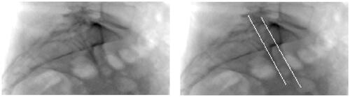
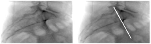
The results of the analysis as described above underlined the need to realign the CT data to ensure that the obtained DRRs showed visual validity with the perioperative fluoroscopy images. An example of the results of DRR calculation after realignment is shown in . The highlighted iliac lines are now superimposed (right image). Both iliac lines visible in the blank DRR shown in have converged into one on the blank DRR in .
Figure 2. A blank DRR after realigning the CT data (l) and a DRR based on realigned CT data on which the anterior iliac surface just lateral to the SIJ has been highlighted on the left and right side (r).
Implementation of the proposed DRR generation and image processing workflow resulted in DRRs that generally showed acceptable visual agreement with the perioperative fluoroscopy images (first and second column of ). It can be seen that visible bone structures in both the DRR and fluoroscopy images largely show visible validity. Discrepancies between the DRRs and corresponding fluoroscopies can be seen when observing the distortion by soft tissue, image contrast and presence of the implants. Outlines of the S1 and S2 neural foramen can be observed in the outlet views, but the trajectory of the foramen cannot be discerned visually. The neural foramina cannot be identified on the inlet and lateral DRR and fluoroscopy.
Figure 3. Overview showing the perioperative fluoroscopy images (first column) for the outlet (first row), inlet (second row) and lateral (third row) view. The corresponding DRR reconstruction is shown in the second column and the DRR including the superimposed S1 and s2 neural foramen segmentation can be seen in the third column. The fourth column shows the perioperative fluoroscopy with the superimposed, registered S1 and S2 neural foramen segmentation.
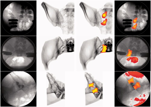
Examples of the implementation of the 3D S1 and S2 neural foramen segmentation into the calculated DRRs are shown in the third column of . Visual assessment of the position of the segmentation on the outlet view shows agreement with the position of the observable foramina on the blank DRR and fluoroscopy. Positional validation cannot be conducted for the inlet and lateral view due to their indiscernibility on the corresponding blank fluoroscopy and DRR images. However, visible positions of these segmentations do correspond to the expected positions based on general anatomical knowledge. In relation to the blank DRRs and the blank fluoroscopy images, the segmentations provide additional trajectorial and positional information that cannot be seen on the blank images.
The results of the registration of the segmentation on the DRRs onto the fluoroscopy imaging first show that the segmentations’ shape and size remain unaffected by the registration process (third and fourth column ). Second, comparison of the segmentation position on the fluoroscopy shows consistency and agreement with the segmentation position on the DRR. The position of the segmentations on the outlet fluoroscopy furthermore corresponds to the visible outlines of the S1 and S2 foramen on the blank fluoroscopy. Some degree of visualization distortion can be observed in the inlet and lateral segmented fluoroscopy, which corresponds to bright structures on the blank fluoroscopy.
The mean and standard deviation of the displacement distance was lowest for the registration of the outlet DRR and corresponding fluoroscopy with 1.91 and 0.79 mm, respectively (). The largest displacement errors were found for the lateral DRR-fluoroscopy registration.
Table 1. Mean and standard deviation of the Euclidean displacement distances between ten corresponding reference points selected on the fluoroscopy and registered DRR.
4. Discussion
4.1. Findings and interpretation
This study successfully implemented the proposed DRR-fluoroscopy registration approach with the aim of enhancing perioperative landmark detection and surgical navigation. Post-operative, retrospective assessment of the feasibility of this approach successfully identified the spatial relation between navigational lines on fluoroscopy and their corresponding position in CT data.
Development of an algorithm resulting in DRRs comparable to perioperative fluoroscopy images was achieved. Visual comparison of the perioperatively obtained fluoroscopy and the generated DRRs showed acceptable agreement between visualized bone structures. It was observed that thresholding the CT data reduced soft tissue interference on the DRRs and resulted in enhanced visualization of bone structures in comparison to the perioperative fluoroscopies. These results indicate that perioperative imaging during SIJF can be enhanced which could potentially improve implant positioning and clinical outcomes.
Although visually valid DRRs were obtained, one intrinsic factor within the proposed approach might have decreased DRR accuracy. The DRR algorithm does not incorporate the magnification factor that is present in the obtained fluoroscopy images correctly as it simulates a line source instead of a point source. Although not clearly visible, this factor intrinsically reduced the similarity between the fluoroscopy and DRR images. Implementing a point source, which was not available in this study, could potentially resolve this issue. Additional discrepancies between fluoroscopy and DRRs could be caused by different patient position during data acquisition, as the CT scan was obtained in supine position while the perioperative fluoroscopy images were acquired in prone position. Obtaining CT scans and fluoroscopy imaging in identical positions could resolve this limitation. Despite the increased bone visualization on the DRRs, thresholding introduced considerable visible discrepancies between the fluoroscopy and DRRs on soft tissue and image contrast. It is expected that these discrepancies hindered the implementation of an automatic intensity-based and feature/landmark-based registration algorithm as a high degree of mutual information is lacking [Citation18].
The lack of mutual information underlined the need for a manual registration approach. Implementation of the manual registration approach to transform the DRR segmentations onto the perioperative fluoroscopy yielded overall visually acceptable results. Implant position and the registered neural foramen segmentations are clearly visible on most fluoroscopy images, which underline the possible benefit of perioperative registration of the S1 and S2 segmentations.
However, although superimposing the segmentations onto the blank fluoroscopy images enhances the visibility of the foramen position and trajectory, it also might cloud the identification of relevant structures and sometimes the implant itself. This was especially the case on the lateral view, where the anterior iliac and alar borders and most superior implant are hard to identify because of the overlayed segmentation. To ensure that the visibility of relevant structures or the implant is not impeded by the segmentations, it should be made possible to easily switch between blank fluoroscopy images and the fluoroscopies with the registered segmentation. Additionally, identification of the safe corridor in which the implants can be placed should always be conducted based on reviewing multiple viewing angles. While the segmentation on the lateral view might cloud the safe corridor, the segmentations might enhance its identification on the other views, leading to an overall enhanced visualization of the safe corridor.
Despite obtaining visually acceptable results, the registration displacement error analysis revealed considerable errors. In relation to comparable literature, the calculated displacement errors are relatively high. Chang et al. calculated a mean displacement error of 0.22 mm when implementing a 2D fluoroscopy/3D CT registration approach for spinal surgery and Uneri et al. showed projection distance errors <0.1 mm in a study on 3D–2D spinal image registration [Citation15,Citation19]. Studies in other fields of medicine have furthermore shown displacement errors <1 mm when implementing a 2D fluoroscopy/3D CT registration approach [Citation20–22]. The displacement errors identified in this study can be attributed to (1) registration errors, (2) errors in the displacement analysis and (3) the selection of registration points. Since both the registration and displacement error analysis rely on manual selection of reference/control points, accurate selection of these points is crucial. However, this process is hindered by the relative low resolution of the DRR and interfering soft tissue on fluoroscopy. The true accuracy of the displacement error analysis and the registration thus remains largely unknown. While the mean measured displacement errors are high and for the lateral view in the order of available implant diameters (4 or 7 mm), further assessment of the accuracy of the proposed approach should be performed before implementation in daily practice. A phantom study based on a 3D pelvic model could be performed in order to further study the registration accuracy. Additionally, the inter-rater reliability of selecting registration points should be studied, as this has not been evaluated in this study.
Available literature on DRR-based registration has underlined the clinical implementation constraints of the computational need for these approaches [Citation14]. The fact that the SIJ fusion procedure is focused around four fluoroscopy image recordings allowed for offline pre-computation of a subspace of DRRs as suggested by Fu and Kuduvalli and Jans et al. [Citation23,Citation24]. It is expected that this approach should allow for acceptable DRR-fluoroscopy registration times and that this method enhances perioperative implementation of the proposed approach. This should, however, be studied in a feasibility study on implementation of the proposed approach.
4.2. Study limitations
This study had several limitations of which the most important aspect is the requirement of manual selection of reference points needed to perform the image registration and the registration analysis. Although this approach ensures a successful registration, it introduces some degree of human error and decreases the registration accuracy. Frühwald et al. identified a significant reduction in registration error when comparing automated registration to manual registration in lower abdomen slice-to-volume registration [Citation25]. Based on these findings and the described difficulties in selecting identical reference points, it is thus expected that the manual registration increased the registration error. Introducing more clearly visible (fiducial) markers on the CT scans and fluoroscopy might increase the registration accuracy and reduce the registration error, displacement distance error and registration times [Citation26].
Closely related to the aforementioned limitations is the constraint that the implemented approach only performs optimization of the registration error on a local level. The registration algorithm calculates the spatial transformation that results in the lowest sum of squared differences between the reference points, neglecting distant similarities and discrepancies. It is assumed that this approach ensures accurate registration of the S1 and S2 foramen, given that the registration points are selected close to these structures of interest. However, this approach limits the ability to accurately inference on the relation between anatomical structures on the fluoroscopy and registered DRR located more distant from the reference points. If successive studies focus on this type of inferencing, the currently proposed approach should be modified.
A clinical implementation limitation is that the implemented algorithm is considerably laborious, since manual segmentations have to be made, a manual threshold must be selected and an ROI has to be drawn. Additionally, the registration process requires time-consuming and manual intervention. Overall, the current approach takes approximately 35 min to complete for one patient. This currently hinders implementation, evaluation and validation, which ultimately hinders the algorithms’ adoption by trauma surgeons and its application during SIJ fusion surgery. Semantic deep learning approaches to automate the segmentation process and automatic registration algorithms may help to overcome these barriers.
While this study focused on assessing the feasibility of developing the proposed approach, we included and analyzed data from only one patient. Therefore, the reproducibility of this approach and accuracy of the presented results cannot be clearly discussed here. Analyzing the performance of the proposed approach on more patient data can result in better inferencing on the reproducibility and accuracy.
4.3. Future research
Future research should focus on further enhancement of perioperative navigation based on CT-fluoroscopy integration. The 360° DRRs allow us to pre-operatively select viewing angles that optimally display the S1 and S2 foramen, the additionally included landmarks and/or any room for implant placement. Perioperative alignment of the C-arm corresponding to the selected optimal DRR viewing angles might improve the ease of perioperative navigation.
Alternatively, a reversed approach can also be explored in which fluoroscopy images are perioperatively compared and registered to the 3D DRR matrix to identify the fluoroscopy images’ orientation and positioning in 3D space. Both approaches could be developed based on geometric calibration of C-arm and patient position relative to the world coordinate system of the operation room [Citation27].
Finally, comparing the final algorithm against more advanced image guidance techniques and software, such as Philips’s XperGuide system, might provide valuable insight in the benefit and validity of the proposed approach [Citation28].
5. Conclusion
This study proved that integration of a 3D CT and perioperative 2D fluoroscopy to register segmented S1 and S2 foramen position and trajectory onto perioperative imaging is feasible. However, the reproducibility, accuracy and actual perioperative implementation of the proposed approach remain unknown. Additional integration of 3D CT and 2D fluoroscopy could further enhance perioperative navigation and should be studied to ensure optimal clinical benefit of the proposed approach.
Disclosure statement
S. H. van Helden: Health Care Professional consulting agreement with SI-BONE
The other authors report no conflict of interest.
References
- Schwarzer AC, Aprill CN, Bogduk N. The sacroiliac joint in chronic low back pain. Spine. 1995;20(1):31–37.
- Sembrano JN, Polly DW. How often is low back pain not coming from the back? Spine. 2009;34(1):E27–E32.
- Cohen SP, Chen Y, Neufeld NJ. Sacroiliac joint pain: a comprehensive review of epidemiology, diagnosis and treatment. Expert Rev Neurother. 2013;13(1):99–116.
- Benzon HT, Raja S, Liu SS, et al. 2018. Essentials of pain medicine: chapter 66 – sacroiliac joint pain. Philadelphia (PA): Elsevier; p. 601–612.e2.
- Lingutla K, Gudipati S, Pollock R, et al. Sacroiliac joint fusion for low back pain: a systematic review and meta-analysis. Spine J. 2015;15(0 ):S54.
- Bronsard N, Pelletier Y, Andréani O, et al. O-arm-guided sacroiliac joint injection: new techniques with reflux test. Orthop Traumatol Surg Res. 2020;106(2):281–283.
- Smith A, Capobianco R, Cher D, et al. Open versus minimally invasive sacroiliac joint fusion: a multi-center comparison of perioperative measures and clinical outcomes. Ann Surg Innov Res. 2013;7(1):14. 7–14
- Ledonio C, Polly D, Swiontkowski MF, et al. Comparative effectiveness of open versus minimally invasive sacroiliac joint fusion. Med Devices (Auckl). 2014;7:187.
- Whang P, Cher D, Polly D, et al. Sacroiliac joint fusion using triangular titanium implants vs. non-surgical management: six-month outcomes from a prospective randomized controlled trial. Int J Spine Surg. 2015;9:6.
- Darr E, Meyer SC, Whang P, et al. Long-term prospective outcomes after minimally invasive trans-iliac sacroiliac joint fusion using triangular titanium implants. Med Devices (Auckl). 2018;11:113–121.
- Heiney J, Capobianco R, Cher D. A systematic review of minimally invasive sacroiliac joint fusion utilizing a lateral transarticular technique. Int J Spine Surg. 2015;9:40.
- Tran ZV, Ivashchenko A, Brooks L. Systematic review sacroiliac joint fusion methodology-minimally invasive compared to screw-type surgeries: a systematic review and meta-analysis. Pain Physician. 2019;22:29–40.
- Miller LE, Reckling WC, Block JE. Analysis of postmarket complaints database for the iFuse SI joint fusion system®: a minimally invasive treatment for degenerative sacroiliitis and sacroiliac joint disruption. Med Devices. 2013;6:77.
- Markelj P, Tomaževič D, Likar B, et al. A review of 3D/2D registration methods for image-guided interventions. Med Image Anal. 2012;16(3):642–661.
- Chang CJ, Lin GL, Tse A, et al. Registration of 2D C-arm and 3D CT images for a C-arm image-assisted navigation system for spinal surgery. Appl Bionics Biomech. 2015;2015:1–9.
- Bhat V, Bhat SN, Anitha H. Accelerated digitally reconstructed radiograph generation scheme for 2D to 3D image registration of vertebrae based on sparse sampling and multi-resolution. 2017 Ninth International Conference on Advanced Computing (ICoAC). IEEE; 2017. p. 51–57.
- Yushkevich PA, Piven J, Hazlett HC, et al. User-guided 3D active contour segmentation of anatomical structures: significantly improved efficiency and reliability. Neuroimage. 2006;31(3):1116–1128.
- Abdel-Basset M, Fakhry AE, El-Henawy I, et al. Feature and intensity based medical image registration using particle swarm optimization. J Med Syst. 2017;41(12):197.
- Uneri A, Otake Y, Wang A, et al. 3D–2D registration for surgical guidance: effect of projection view angles on registration accuracy. Phys Med Biol. 2013;59(2):271–287.
- Roth M, Dötter M, Burgkart R, et al. Fast intensity-based fluoroscopy-to-CT registration using pattern search optimization. Int Congress Ser. 2004;1268:165–170.
- Otake Y, Wang AS, Stayman J, et al. Robust 3D–2D image registration: application to spine interventions and vertebral labeling in the presence of anatomical deformation. Phys Med Biol. 2013;58(23):8535–8553.
- Duménil A, Kaladji A, Castro M, et al. A versatile intensity-based 3D/2D rigid registration compatible with mobile C-arm for endovascular treatment of abdominal aortic aneurysm. Int J Comput Assist Radiol Surg. 2016;11(9):1713–1729.
- Fu D, Kuduvalli G. A fast, accurate, and automatic 2D-3D image registration for image-guided cranial radiosurgery. Med Phys. 2008;35(5):2180–2194.
- Jans H-S, Syme AM, Rathee S, et al. 3D interfractional patient position verification using 2D-3D registration of orthogonal images. Med Phys. 2006;33(5):1420–1439.
- Frühwald L, Kettenbach J, Figl M, et al. A comparative study on manual and automatic slice-to-volume registration of CT images. Eur Radiol. 2009;19(11):2647–2653.
- Krishnan R, Hermann E, Wolff R, et al. Automated fiducial marker detection for patient registration in image-guided neurosurgery. Comput Aided Surg. 2003;8(1):17–23.
- Silva TD, Punnoose J, Uneri A, et al. C-arm positioning using virtual fluoroscopy for image-guided surgery. Medical imaging 2017: image-guided procedures, robotic interventions, and modeling. Bellingham (WA): SPIE; 2017.
- Leschka SC, Babic D, Shikh SE, et al. C-arm cone beam computed tomography needle path overlay for image-guided procedures of the spine and pelvis. Neuroradiology. 2011;54(3):215–223.