
Abstract
Purpose
To investigate the accuracy of an imageless, optical surgical navigation tool to assist with femoral and tibial bone cuts performed during TKA.
Patients and methods
Six board-certified orthopedic surgeons participated in a laboratory cadaver investigation, performing femoral and tibial bone cuts with the assistance of a computer navigation tool. Femoral and tibial varus/valgus, tibial slope, femoral flexion, and both femoral and tibial rotation measurements from the device were compared with angular measurements calculated from computed tomography (CT) images of the knees.
Results
Measurements with the navigation tool were highly correlated with those obtained from CT scans in all three axes. For the distal femoral cut, the absolute mean difference in varus/valgus was 0.83° (SD 0.46°, r = 0.76), femoral flexion was 1.91° (SD 1.16°, r = 0.85), and femoral rotation was 1.29° (SD 1.01°, r = 0.88) relative to Whiteside’s line and 0.97° (SD 0.56°, r = 0.81) relative to the posterior condylar axis. For the tibia, the absolute mean difference in varus/valgus was 1.08° (SD 0.64°, r = 0.85), posterior slope was 2.78° (SD 1.40°, r = 0.60), and rotation relative to the anteroposterior axis (posterior cruciate ligament to the medial third of the tibial tuberosity) was 2.98° (SD 2.54°, r = 0.79).
Conclusion
Utilization of an imageless navigation tool may aid surgeons in accurately performing and monitoring femoral and tibial bone cuts, and implant rotation in TKA and thus, more accurately align TKA components.
Introduction
Total knee arthroplasty (TKA) is a common and effective procedure to alleviate knee pain from degenerative osteoarthritis and correct knee deformity and instability. TKA procedures are increasing, with a more active, aging population creating a growing demand [Citation1,Citation2]. A recent analysis suggests the number of primary TKAs performed in the United States is predicted to rise 85% over the next 10 years to an estimated 1.26 million procedures per year [Citation3].
While associated with a high rate of success and 25-year survivorship rates of 80% [Citation4], revision surgery still occurs, with revision procedures accounting for 5–9% of the total TKAs performed annually [Citation1,Citation5]. Typical complications include component loosening, instability, dislocation, infection, and fracture [Citation6], with a large proportion of patients – up to 20–25% by some reports – reporting minor complications including knee pain or reduced range of motion [Citation7–10]. Proper implant and joint stability are keys to minimizing these complications, with restoration of joint alignment paramount in returning range of motion and improving quality of life [Citation11]. Mechanical alignment remains the most common technique used in TKA, however there has been an increase in surgeons who use kinematic alignment or a combined approach. Common to any approach is the goal of resecting a pre-planned axis with a high degree of accuracy [Citation12]. The inability to achieve accurate alignment has been shown to contribute to component loosening [Citation11], increased wear, and reduced range of motion, which ultimately affects patient satisfaction and implant longevity [Citation13]. One study reported that when varus/valgus alignment exceeded 3° of the mechanical axis, aseptic loosening occurred 24% of the time [Citation11], while a second study reported a 17.2 times greater rate of implant failure when tibia alignment was greater than 3° varus [Citation13].
Computer-assisted navigation systems (CAN) have been developed to improve the accuracy and precision of component placement in TKA. While adoption in some countries such as Australia is growing (up to 33.2%) [Citation5], in the U.K. and U.S., only 3.5% of TKA procedures annually are performed with navigation assistance, according to a 2014 report [Citation14]. Despite this limited adoption, there is ample evidence to support that CAN is associated with an improvement in the alignment of femoral and tibial components in TKA [Citation15–20]. Meta-analyses showed that not only was TKA performed with computer navigation more likely than conventional surgery to achieve optimal alignment (within 3°) [Citation21], but patients undergoing navigated surgery had a 25% reduced risk of malalignment over 3° compared to conventional surgery [Citation22]. Adoption of CAN has been hindered somewhat by perceived disadvantages such as a high initial capital investment and the cost per case [Citation23–25], and potential increases in surgery duration [Citation22] however, newer imageless systems have largely eliminated these concerns, and there is evidence that imageless navigation does not significantly increase surgery duration [Citation26].
Intellijoint KNEETM (IJK; Intellijoint Surgical Inc., Kitchener, Ontario, Canada) is an imageless optical surgical navigation tool that provides real-time intra-operative measurements of femoral and tibial bone cut angles during TKA. To assess the initial accuracy of the surgical navigation tool in performing both distal femur and proximal tibia bone cuts and assessing varus/valgus, rotation, and flexion/slope of these cuts during TKA, an investigation utilizing cadaveric knees was conducted. It was hypothesized that the navigation guided bone cut measurements would be comparable with angular measurements calculated from computed tomography (CT) images.
Material and methods
Testing consisted of two sessions during which six board-certified orthopedic surgeons operated on seventeen cadaveric knees. Each surgeon performed at minimum two (maximum five) total knee arthroplasty (TKA) procedures consisting of proximal tibia and distal femur cuts using their preferred surgical approach on the cadaveric specimens. The first session tested the femoral and tibial varus/valgus, femoral flexion, and tibial slope accuracy in five cadavers (10 knees). The second session focused on measurements in the transverse plane for both the distal femoral and tibial rotation in four additional cadavers (7 knees). In these seven knees, the anterior chamfer cut was also made on each femur.
Tissue for the laboratory was supplied by BioGift Anatomical via the Mobile Medical Training Unit (New Jersey, USA). BioGift abides by the Uniform Anatomical Gift Act, the National Organ Transplant Act, prohibiting the buying or selling of human organs or tissues, the Health Insurance Portability and Accountability Act, and the U.S. Code of Federal Regulations Title 45, Part 46, protecting donor confidentiality. Testing adhered to the Declaration of Helsinki.
Imageless computer navigation system
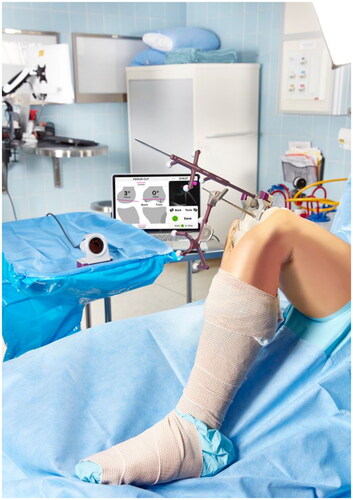
An imageless optical navigation tool (Intellijoint Surgical, Inc., Kitchener, Ontario, Canada) that uses infrared optical technology and integrated microelectronics to monitor the real-time position of the femur and tibia cutting guides during TKA was utilized. This pinless, miniature, surgeon-controlled tool provided real-time intra-operative measurements displayed on a computer workstation located outside the sterile field. The system consisted of an optical bone tracker attached to either the femur or tibia with a bone screw, an optical probe tracker used for registration and monitoring cutting guide position, and an infrared camera mounted within the sterile field (refer to ). The camera was placed where it could detect the position and orientation of the trackers within its field of view and communicate with the computer workstation, where positional measurements were displayed to the surgeon using application software. The varus/valgus angle, femoral flexion and tibial slope angles of the femur and tibia cuts were measured relative to the mechanical axis of the respective bone. The rotational values were measured relative to Whiteside’s line and the posterior condylar axis (PCA) for the femur and the anteroposterior (AP) axis for the tibia, defined as a line connecting the posterior cruciate ligament (PCL) insertion to the medial third of the tibial tuberosity (MTT).
Figure 1. Intra-operative set up of Intellijoint KNEE during the femur cut verification step. The 3D mini optical navigation device consists of an infrared camera within the sterile field which tracks markers on the bone tracker (mounted on the femur or tibia) and the probe tracker which fits into the cutting guide slot to verify the cut. Data is relayed to the computer workstation outside of the sterile field and displayed in real time. The device can be controlled by the surgeon with the buttons on the camera or by an assistant at the workstation.
Procedure
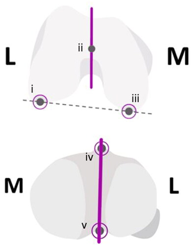
Torso-to-toe specimens were positioned supine on the operating table and secured with peg boards. Exposure of the knee was conducted by surgeons using their favored technique; surgeons chose a femur-first or tibia-first workflow depending on their preference. The registration process for the navigation tool requires digitization of each of the femur and tibia. Femoral registration first involved identifying the hip center of rotation, followed by probing of the femur center, defining of the AP axis (i.e. Whiteside’s line) and registering the lateral and medial condyles using the tip of the optical probe tracker. Tibial registration followed a similar process, with the optical tracker/probe used to define the lateral and medial malleoli, and AP axis (see ). These landmarks were recorded relative to an optical tracker that was fixed to the bone of interest via intra-articular or extra-articular placement, the latter allowing for post-cut verification of the cut angle.
Figure 2. The Top image depicts the landmarks on the femur: (i) lateral condyle, (ii) femur center, (iii) medial condyle, solid line is the AP axis (whiteside’s line), dashed is the posterior condylar axis. The image below depicts the tibial landmarks: (iv) medial third of the tibial tuberosity (MTT) and (v) the PCL insertion point, solid line is the AP axis.
Measurements in the coronal plane (i.e. varus/valgus) and the sagittal plane (i.e. femoral flexion and tibial slope) were made relative to the mechanical axis of the femur or tibia. Coronal plane values were measured by the navigation tool as the deviation from the mechanical axis, with varus denoted by a positive value and valgus denoted by a negative value. These values correspond to the mechanical lateral distal femoral angle (mLDFA) and the mechanical medial proximal tibial angle (mMPTA) as measured on radiographs. Sagittal plane measurements from the navigation tool and from post-operative imaging were made relative to the anatomical axis of the femur and tibia, with femoral flexion and posterior tibial slope angles denoted by positive values.
Measurements in the transverse plane (i.e. rotation) required the registration of additional landmarks during the tibial workflow such as the PCL insertion point and the MTT. To allow for CT measurements, surface-based registration was also performed using the medial and lateral condyles and the trochlear groove during the femoral registration. For these measurements, extra-articular fixation of the probe/tracker was utilized and additional landmarks were defined during registration to provide reference lines for comparison. Following the distal cut to the femur, the most posterior aspects of the medial and lateral posterior condyles were probed, as well as the lateral and medial epicondyles, allowing for the definition of the posterior condylar axis (PCA) and the trans-epicondylar axis (TEA). Following the distal femoral cut, chamfer cuts were made using each surgeon’s preferred rotational instrument (e.g. sizing guide and ‘4-in-1’ cutting guide). Rotation measurements of the femoral cut were established by the navigation tool relative to both the PCA and Whiteside’s line while tibial measurements were made relative to the line bisecting the PCL insertion and the MTT.
For all cuts, a 1.35 mm sawblade was used. Attachment of the probe to a flat base allowed for post bone cut verification of the cut angle by placing the base of the tracker directly on the cut surface of the bone. The flat base also allowed for measurement of the orientation of the cutting guide when inserted into the guide slot.
Imaging and image analysis
Cadaveric specimens were analyzed using CT imaging. Long leg CT scans from the acetabular roof to the talar dome were obtained pre- and post-operatively. Scans were obtained with a GE LightSpeed VCT CT system, using a 0.625 mm slice thickness (GE Healthcare, Chicago, Illinois) and a Supria CT system, with a 0.755 mm slice thickness (Hitachi Medical Corporation, Tokyo, Japan). Scans were segmented in 3D Slicer (v.4.10.1 and v4.11.20210226) to create 3D models of the femur and tibia. The mechanical and rotational axes were registered using anatomical landmarks. Angles of the bone cuts on the post-operative CT scan were based on the plane of best fit in relation to the registered mechanical and rotational axes. For the femoral rotation analysis, the intersection between the distal and anterior cuts was calculated to correspond directly to the rotation angles from each reference axis. All calculations were performed using MATLAB® software (MathWorks, Inc., Natick, Massachusetts).
Femoral axis definitions
During image analysis, the medial-lateral axis was defined as the cross-product of the superior-inferior and anterior-posterior axes. The superior-inferior axis was defined as the line from the center of the femoral head to the femoral knee center. The femoral knee center was defined as the most anterior point in the middle of the femoral notch, aligning the hip center with the roof of the femoral notch. The anterior-posterior axis was defined by the projection of Whiteside’s line onto the axial plane. The posterior condylar axis (PCA) was defined as the vector between the most prominent points of the two posterior condyles.
Tibial axis definitions
The medial-lateral axis was defined as the cross-product of the superior-inferior and anterior-posterior axes. The superior-inferior axis was defined as the line from the tibial knee center to the ankle center (determined as a weighted average (57:43) of the lateral and medial malleoli of the tibia). The anterior-posterior axis was defined by the line connecting the tibial knee center (articular bone tracker placement) or the PCL insertion (extra-articular placement) to the medial third of the tibial tuberosity.
Statistical analysis
The mean absolute difference in degrees between the navigation tool measurements and measurements calculated from CT scans was determined for varus/valgus, flexion/extension and rotation measurements for the femoral and tibial cuts and correlated using Pearson’s correlations. Data are presented as mean (standard deviation (SD)). Navigation and CT measurements were also compared using the Bland-Altman technique which evaluates the level of agreement between the two clinical measurements.
Results
Bone cut angle measurements were collected from seventeen knee specimens (three females and six males) that were prepared with the assistance of the imageless navigation tool. For the femoral cuts, the absolute mean difference in varus/valgus was 0.83° (SD 0.46°, r = 0.76), in flexion was 1.91° (SD 1.16°, r = 0.85), and in rotation was 1.29° (SD 1.01°, r = 0.88) relative to Whiteside’s line and 0.97° (SD 0.56°, r = 0.81) relative to the posterior condylar axis (see ). For the tibia, the absolute mean difference in varus/valgus was 1.08° (SD 0.64°, r = 0.85), the posterior slope was 2.78° (SD 1.40°, r = 0.60), and rotation was 2.98° (SD 2.54°, r = 0.79). Bland-Altman analyses demonstrated that 100% of paired varus/valgus measurements and 95% of paired femoral flexion/tibial slope and rotational measurements were within the statistical limit for agreement ( and ).
Figure 3. Bland-Altman plots showing agreement between intraoperative device (Intellijoint KNEE; IJK) measurements and post-operative CT scans for varus/valgus (A) and combined femur flexion and tibial slope (B). The average difference between the two measurements is expressed relative to the average of the two (n = 20; two values from each of the ten cadaveric knees utilized in the coronal and sagittal measurements). 100% of paired measurements were within the statistical limits (±1.96 × SD, dashed lines) for acceptable agreement in varus/valgus and 95% were within the statistical limits for femur flexion/tibial slope.
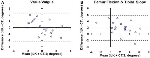
Figure 4. Bland-Altman plots showing agreement in the transverse plane cuts guided by Intellijoint KNEE (IJK) including femur rotation (A) and tibial rotation (B). the average difference between the two measurements is compared with the average of the two measurements. 100% of paired measurements were within the statistical limits (±1.96 × SD, dashed lines) for acceptable agreement in tibial rotation and 93% of measurements were in agreement for femur rotation. The femoral rotation values combine data referenced from both whiteside’s line and the PCA (n = 14), while tibial values are derived from the PCL-MTT axis only (n = 7).
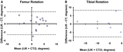
Table 1. Angular intraoperative values from the device’s use during cadaveric laboratories compared to post-operative CT scan results.
Discussion
Accurate alignment of components in TKA is critical to ensure a successful procedure and minimize future complications. Alignment to within ±3° of the mechanical axis is generally accepted as a goal of TKA [Citation11,Citation27]. Consequences of malalignment may include an asymmetric extension gap, contributing to increased wear, component loosening, limited range of motion, and potentially implant failure [Citation6,Citation11,Citation13]. Computer navigation systems have been developed to increase the accuracy and precision of component placement in TKA, with the present study finding that an imageless optical navigation tool was accurate in performing and measuring femoral and tibial bone cuts as compared to measurements from CT images. The absolute mean difference between the navigation device and imaging was within 2° for varus/valgus, flexion/extension and rotation of the femur, while tibial measurements for these axes were within 3°. Tibial AP rotation was the measurement associated with the most error, however, the target goals associated with this measurement remain contested in the field [Citation28]. Many surgeons will rely on the 'self range-of-motion technique’ to rotationally align the component, so the value of this variable is unlikely to alter the surgical plan, but rather to provide additional data to make minor tweaks or characterize long-term intraoperative positioning between patients.
Several factors may adversely influence component alignment in TKA, including variations in patient anatomy and the intricacies of using alignment guides and cutting blocks. Regardless of the cause, cutting errors have been identified as a potentially significant source of error contributing to accurate component placement [Citation29–31]. Observed errors are generally higher for cuts in the sagittal plane, with cadaveric work reporting maximum errors in the range of 1–2° for varus/valgus and 3–4° for flexion/extension [Citation30], and clinical studies demonstrating similar magnitudes of error, with one large retrospective review showing average absolute cutting errors of 0.8°–1.3° in the coronal plane and 1.3°–1.6° in the sagittal plane [Citation31]. The guides generally used to mitigate these errors, whether extramedullary (EM) or intramedullary (IM), are associated with satisfactory alignment results, with published studies reporting alignment of the mechanical axis within 3° of varus/valgus in approximately 75% of patients [Citation11,Citation15,Citation32]. However, these guides do not completely eliminate the challenges in achieving optimal alignment as movement, such as the rotation of alignment rods within the diaphysis, has been shown to affect cutting planes [Citation33]. Additionally, the insertion of IM guides, even when performed with care, may still be associated with fat and marrow embolization [Citation34], and obese patients present challenges in the accurate placement of alignment guides [Citation35,Citation36]. In general, IM guides may be invasive and disruptive to the femoral bone, while EM guides can be cumbersome. Both rely on the surgeon’s expertise in estimating angles to achieve optimal alignment, and neither has eliminated all potential sources of cutting error and/or iatrogenic injury.
Computer navigation has been shown to reliably improve the accuracy of tibial and femoral component alignment in TKA, with increased accuracy as compared to traditional alignment guides [Citation15,Citation16,Citation18]. Imageless navigation, while still relying on the surgeon’s expertise and instrument control, provides real-time intraoperative monitoring of the cutting planes. This allows for intraoperative adjustments to cuts that would not otherwise be possible and potential avoidance of complications that would not become apparent until follow-up. These benefits, however, rely largely on the ability of the navigation system itself to accurately measure cut angles intraoperatively. The current cadaver investigation sought to evaluate the accuracy of femoral and tibial bone cuts performed with an imageless optical navigation tool by comparing intraoperative measurements with those from CT imaging. We noted a mean absolute difference between the device measurements and those calculated from CT images of less than 3° and observed high levels of correlation between the two measurements. Thirty-nine out of 40 (97.5%) paired measurements (device-CT) were within the statistical limit for agreement in the Bland-Altman analysis. Additionally, the navigation tool may limit trauma to the femur as the use of IM alignment guides are not required. The use of this navigation tool does not require permanent alteration of the operating room or pre-operative CT imaging, increasing the potential cost-effectiveness of this device compared to other navigation options.
Our data are consistent with previous accuracy studies of navigation systems [Citation37–39]. The accuracy of a handheld imageless tool was determined in one study by comparing planned implant and actual implant orientation in 25 cadavers. In that study, both the femoral and tibial cuts were measured to within 3° of the planned implant orientations [Citation37]. In another study, anteroposterior and lateral knee radiographs were compared to CT scans of 10 cadavers (20 knees) to determine if surgeons performing tibial resections could meet a random varus/valgus and posterior slope target using an accelerometer-based navigation device. The results indicated that surgeons were able to resect the tibia to within 3° of the pre-operative targets [Citation38]. Lastly, a study of 70 patients demonstrated the accuracy of an imageless navigation system by comparing the pre- and post-operative navigation and CT measurements for femoral and tibial cuts. Navigation and CT measurements were highly correlated both pre- (r = 0.84) and post-operatively (r = 0.66) [Citation39].
The surgical technique and alignment theories of TKA have changed over the years and remain a widely debated topic in arthroplasty but hitting pre-established alignment and resection targets have remained a consistent goal. Robotic assisted total knee is widely regarded as the gold standard for accuracy, however, there has not been a clear association with improved patient outcomes beyond those achieved with CAN [Citation40]. At one-year post-op, patients with a hip-knee axis within 3 degrees of the mechanical axis had significantly better mental health and functional scores within the SF-12 assessment [Citation41]. CAN was superior to conventional surgery at achieving this outcome (88% of cases compared to 61% in the conventional group) [Citation41]. This improvement was even more pronounced in obese patients where 93% of patients in the CAN group achieved the surgical target of within 3˚ compared to only 56% in the conventional group [Citation41]. The use of any technology for guiding implants that eliminates the use of IM rods has been shown to have a lower risk of early mortality following a procedure [Citation42], which is even more notable in bilateral replacements [Citation43]. Intellijoint KNEE is an easy to use, imageless, cost-effective, and implant agnostic computer assisted navigation device. This study demonstrated the accuracy and robustness of the system to navigate complex measures of knee alignment.
IJK only requires a single tray, and the portable cart has a much smaller footprint in the operating room and lower operational costs than a robotic system. The learning curve for IJK is less than ten cases, and there is no time-add compared to conventional surgery [Citation44]. Conversely, the learning curve of robotics continues to decline until at least a year of use [Citation45] and in an age and sex matched study comparing robot to conventional TKA, conventional surgery was on average 29 min faster [Citation46]. The accuracy of robotics is due to image-based co-registration; however, the tradeoff is the time, added radiation exposure, and cost requirement of having patients acquire pre-operative CT imaging. Intellijoint KNEE is unlike other CAN options because its camera is mobile and used within the sterile field, which eliminates line of sight challenges. In addition, IJK is implant agnostic, giving the surgeons complete autonomy to choose their preferred components in each surgery. While IJK does not offer as many features as other products (e.g. image-based registration) the registration process is less cumbersome for the surgical staff.
Limitations associated with this study include the use of cadaver specimens and the associated drawbacks. There is some concern that frozen tissue may not mimic normal patient movement [Citation47]; however, in this study, the tissue was thawed sufficiently to allow natural movements duplicating that of live human tissue. There was a small bias in the femoral flexion and tibial slope values, however, the laboratory cadaver simulation was the first time the participating orthopedic surgeons had experienced the imageless navigation tool. There is a learning curve associated with any new technology and this potentially influenced the initial accuracy of the surgeons. Proficiency using a navigation tool for total hip arthroplasty developed by the same manufacturer was shown to improve within 3–5 cases [Citation48]. Experience in a clinical setting with the current knee arthroplasty device will likely yield similar improvements, as the technology is very similar to the previously mentioned hip device. Clinical studies are required to confirm the navigation tool’s accuracy in an operating room setting and provide comparisons to conventional alignment guides.
Conclusion
Our study evaluated the ability of an imageless optical navigation tool to accurately measure femoral and tibial cadaver bone cuts in coronal, sagittal, and transverse planes when compared with post-operative CT measurements. We found that the bone cuts and measurements from the navigation tool correlated very well with those from CT scans, with femoral cuts measured to within 2° and tibial cuts measured to within 3° of CT measurements. These results suggest that intra-operative monitoring with the imageless navigation tool may provide valuable real-time data during TKA while avoiding the complications that arise from current mechanical guides. While more research is needed to evaluate the impact of this accuracy on patient outcomes, these results suggest that intraoperative measurements from imageless navigation will correlate well with post-operative measurements from imaging.
Disclosures statement
K.A.F., J.M.M., and E.I.M. are employees of Intellijoint Surgical. R.S., B.M.C., and M.P.B have received consulting fees from the company. All authors except E.I.M. have stock or stock options with the company.
Acknowledgments
The authors would like to acknowledge the research and development team who were responsible for the cadaver lab operations and image analysis, notably Harish Rao, Ryan Visee, and Joe Schipper.
Additional information
Funding
References
- Registry AJR. American joint replacement registry 2018 annual report. Rosemont (IL): AOOS 2018.
- Information CIfH. Hip and knee replacements in Canada, 2016–2017: canadian joint replacement registry annual report. Ottawa (ON): CIHI; 2018.
- Sloan M, Premkumar A, Sheth NP. Projected volume of primary total joint arthroplasty in the U.S., 2014 to 2030. J Bone Joint Surg Am. 2018;100(17):1455–1460. doi: 10.2106/JBJS.17.01617.
- Evans JT, Walker RW, Evans JP, et al. How long does a knee replacement last? A systematic review and meta-analysis of case series and national registry reports with more than 15 years of follow-up. Lancet. 2019;393(10172):655–663. doi: 10.1016/S0140-6736(18)32531-5.
- AOANJRR. Hip, knee & shoulder arthroplasty: 2019 annual report. Adelaide: AOA; 2019.
- Kane RL, Saleh KJ, Wilt TJ, et al. Total knee replacement. Evid Rep Technol Assess. 2003;86:1–8.
- Aglietti P, Buzzi R, Gaudenzi A. Patellofemoral functional results and complications with the posterior stabilized total condylar knee prosthesis. J Arthroplasty. 1988;3(1):17–25. doi: 10.1016/s0883-5403(88)80049-4.
- Figgie HE, Goldberg VM, Heiple KG, et al. The influence of tibial-patellofemoral location on function of the knee in patients with the posterior stabilized condylar knee prosthesis. J Bone Joint Surg Am. 1986;68(7):1035–1040. doi: 10.2106/00004623-198668070-00009.
- Merkow RL, Soudry M, Insall JN. Patellar dislocation following total knee replacement. J Bone Joint Surg Am. 1985;67(9):1321–1327. doi: 10.2106/00004623-198567090-00003.
- Beswick AD, Wylde V, Gooberman-Hill R, et al. What proportion of patients report long-term pain after total hip or knee replacement for osteoarthritis? A systematic review of prospective studies in unselected patients. BMJ Open. 2012;2(1):e000435. doi: 10.1136/bmjopen-2011-000435.
- Jeffery RS, Morris RW, Denham RA. Coronal alignment after total knee replacement. J Bone Joint Surg Br. 1991;73(5):709–714. doi: 10.1302/0301-620X.73B5.1894655.
- Hiranaka T, Suda Y, Saitoh A, et al. Current concept of kinematic alignment total knee arthroplasty and its derivatives. Bone Jt Open. 2022;3(5):390–397. doi: 10.1302/2633-1462.35.BJO-2022-0021.R2.
- Berend ME, Ritter MA, Meding JB, et al. Tibial component failure mechanisms in total knee arthroplasty. Clin Orthop Relat Res. 2004;428(428):26–34. doi: 10.1097/01.blo.0000148578.22729.0e.
- Picard FC, Deep K, Gregori A. Computer assisted knee replacement surgery: is the movement mainstream? Orthop Musc Syst. 2014;3(2):153.
- Nam D, Cody EA, Nguyen JT, et al. Extramedullary guides versus portable, accelerometer-based navigation for tibial alignment in total knee arthroplasty: a randomized, controlled trial: winner of the 2013 HAP Paul award. J Arthroplasty. 2014;29(2):288–294. doi: 10.1016/j.arth.2013.06.006.
- Martin A, Wohlgenannt O, Prenn M, et al. Imageless navigation for TKA increases implantation accuracy. Clin Orthop Relat Res. 2007;460:178–184. doi: 10.1097/BLO.0b013e31804ea45f.
- Sparmann M, Wolke B, Czupalla H, et al. Positioning of total knee arthroplasty with and without navigation support. A prospective, randomised study. J Bone Joint Surg Br. 2003;85-B(6):830–835. doi: 10.1302/0301-620X.85B6.13722.
- Jenny JY, Clemens U, Kohler S, et al. Consistency of implantation of a total knee arthroplasty with a non-image-based navigation system: a case-control study of 235 cases compared with 235 conventionally implanted prostheses. J Arthroplasty. 2005;20(7):832–839. doi: 10.1016/j.arth.2005.02.002.
- Figueroa F, Wakelin E, Twiggs J, et al. Comparison between navigated reported position and postoperative computed tomography to evaluate accuracy in a robotic navigation system in total knee arthroplasty. Knee. 2019;26(4):869–875. doi: 10.1016/j.knee.2019.05.004.
- Bathis H, Perlick L, Tingart M, et al. Alignment in total knee arthroplasty. A comparison of computer-assisted surgery with the conventional technique. J Bone Joint Surg Br. 2004;86(5):682–687. doi: 10.1302/0301-620x.86b5.14927.
- Rebal BA, Babatunde OM, Lee JH, et al. Imageless computer navigation in total knee arthroplasty provides superior short term functional outcomes: a meta-analysis. J Arthroplasty. 2014;29(5):938–944. doi: 10.1016/j.arth.2013.09.018.
- Bauwens K, Matthes G, Wich M, et al. Navigated total knee replacement. A meta-analysis. J Bone Joint Surg Am. 2007;89(2):261–269. doi: 10.2106/JBJS.F.00601.
- Novak EJ, Silverstein MD, Bozic KJ. The cost-effectiveness of computer-assisted navigation in total knee arthroplasty. J Bone Joint Surg Am. 2007;89(11):2389–2397. doi: 10.2106/00004623-200711000-00008.
- Goh GS, Liow MH, Lim WS, et al. Accelerometer-Based navigation is as accurate as optical computer navigation in restoring the joint line and mechanical axis after total knee arthroplasty: a prospective matched study. J Arthroplasty. 2016;31(1):92–97. doi: 10.1016/j.arth.2015.06.048.
- Swank ML, Alkire M, Conditt M, et al. Technology and cost-effectiveness in knee arthroplasty: computer navigation and robotics. Am J Orthop. 2009;38(2 Suppl):32–36.
- Christ A, Ponzio D, Pitta M, et al. Minimal increase in total hip arthroplasty surgical procedural time with the use of a novel surgical navigation tool. Open Orthop J. 2018;12(1):389–395. doi: 10.2174/1874325001812010389.
- Insall J, Scott WN, Ranawat CS. The total condylar knee prosthesis. A report of two hundred and twenty cases. J Bone Joint Surg Am. 1979;61(2):173–180. doi: 10.2106/00004623-197961020-00003.
- Indelli PF, Graceffa A, Marcucci M, et al. Rotational alignment of the tibial component in total knee arthroplasty. Ann Transl Med. 2016;4(1):3.
- Bathis H, Perlick L, Tingart M, et al. Intraoperative cutting errors in total knee arthroplasty. Arch Orthop Trauma Surg. 2005;125(1):16–20. doi: 10.1007/s00402-004-0759-1.
- Plaskos C, Hodgson AJ, Inkpen K, et al. Bone cutting errors in total knee arthroplasty. J Arthroplasty. 2002;17(6):698–705. doi: 10.1054/arth.2002.33564.
- Yau WP, Chiu KY. Cutting errors in total knee replacement: assessment by computer assisted surgery. Knee Surg Sports Traumatol Arthrosc. 2008;16(7):670–673. doi: 10.1007/s00167-008-0550-x.
- Engh GA, Petersen TL. Comparative experience with intramedullary and extramedullary alignment in total knee arthroplasty. J Arthroplasty. 1990;5(1):1–8. doi: 10.1016/s0883-5403(06)80002-1.
- Maderbacher G, Matussek J, Keshmiri A, et al. Rotation of intramedullary alignment rods affects distal femoral cutting plane in total knee arthroplasty. Knee Surg Sports Traumatol Arthrosc. 2018;26(11):3311–3316. doi: 10.1007/s00167-018-4875-9.
- Hall TM, Callaghan JJ. Fat embolism precipitated by reaming of the femoral canal during revision of a total knee replacement. A case report. J Bone Joint Surg Am. 1994;76(6):899–903. doi: 10.2106/00004623-199406000-00014.
- Bolognesi M, Hofmann A. Computer navigation versus standard instrumentation for TKA: a single-surgeon experience. Clin Orthop Relat Res. 2005;440:162–169. doi: 10.1097/01.blo.0000186561.70566.95.
- Laskin RS, Beksac B. Computer-assisted navigation in TKA: where we are and where we are going. Clin Orthop Relat Res. 2006;452:127–131. doi: 10.1097/01.blo.0000238823.78895.dc.
- Lonner JH, Smith JR, Picard F, et al. High degree of accuracy of a novel image-free handheld robot for unicondylar knee arthroplasty in a cadaveric study. Clin Orthop Relat Res. 2015;473(1):206–212. doi: 10.1007/s11999-014-3764-x.
- Nam D, Dy CJ, Cross MB, et al. Cadaveric results of an accelerometer based, extramedullary navigation system for the tibial resection in total knee arthroplasty. Knee. 2012;19(5):617–621. doi: 10.1016/j.knee.2011.09.008.
- Batash R, Rubin G, Lerner A, et al. Computed navigated total knee arthroplasty compared to computed tomography scans. Knee. 2017;24(3):622–626. doi: 10.1016/j.knee.2017.03.006.
- Clark G, Steer R, Tippett B, et al. Short-Term benefits of robotic assisted total knee arthroplasty over computer navigated total knee arthroplasty are not sustained with no difference in postoperative Patient-Reported outcome measures. Arthroplast Today. 2022;14:210–215 e210. doi: 10.1016/j.artd.2021.11.014.
- Choong PF, Dowsey MM, Stoney JD. Does accurate anatomical alignment result in better function and quality of life? Comparing conventional and computer-assisted total knee arthroplasty. J Arthroplasty. 2009;24(4):560–569. doi: 10.1016/j.arth.2008.02.018.
- Harris IA, Kirwan DP, Peng Y, et al. Increased early mortality after total knee arthroplasty using conventional instrumentation compared with technology-assisted surgery: an analysis of linked national registry data. BMJ Open. 2022;12(5):e055859. doi: 10.1136/bmjopen-2021-055859.
- Kirwan DP, B(imis) YP, Harris IA. Increased early mortality in bilateral simultaneous TKA using conventional instrumentation compared with Technology-Assisted surgery: a study of 34,908 procedures from a national registry. JBJS. 2021;103(23):2177–2180. doi: 10.2106/JBJS.21.00029.
- Zabat MA, Oakley CT, Marwin SE, et al. The learning curve associated with imageless navigation in total knee arthroplasty. Arch Orthop Trauma Surg. 2023;143(2):1013–1019. doi: 10.1007/s00402-022-04373-w.
- Marchand KB, Ehiorobo J, Mathew KK, et al. Learning curve of Robotic-Assisted total knee arthroplasty for a high-volume surgeon. J Knee Surg. 2022;35(4):409–415. doi: 10.1055/s-0040-1715126.
- Bollars P, Boeckxstaens A, Mievis J, et al. Preliminary experience with an image-free handheld robot for total knee arthroplasty: 77 cases compared with a matched control group. Eur J Orthop Surg Traumatol. 2020;30(4):723–729. doi: 10.1007/s00590-020-02624-3.
- Renkawitz T, Schuster T, Herold T, et al. Measuring leg length and offset with an imageless navigation system during total hip arthroplasty: is it really accurate? Int J Med Robot. 2009;5(2):192–197. doi: 10.1002/rcs.250.
- Muir JM. The learning curve for a new surgical navigation tool in total hip arthroplasty: a review of cases using Intellijoint HIP. Ontario, Canada: Intellijoint Surgical, Inc.; 2016.