
 ?Mathematical formulae have been encoded as MathML and are displayed in this HTML version using MathJax in order to improve their display. Uncheck the box to turn MathJax off. This feature requires Javascript. Click on a formula to zoom.
ABSTRACT
Applying the directionality of an acoustic meta-lens, a sound reception system for ships is designed. A two-dimensional disk shape acoustic meta-lens or an acoustic Luneburg lens made of 253 acrylic pipes of different radii which control the refractive index is used. The lens has the diameter of 180 cm and the thickness of 20 cm. Eight microphones were installed around the edges of the lens because the lens focuses the input signal into the edge of the other side of the lens. The sound reception ability of the lens was tested on the sea using the horn of a university training ship as an emitter and the lens loaded on a small boat as a receiver. Both are moving at 20 ~ 40 km/h at a distance between 300 ~ 700 m. The lens could focus to recognize the direction of the input sound in the frequency range between 300 and 900 Hz.
ABBREVIATIONS IMO: International Maritime Organization ALL: Acoustic Luneburg Lens SRS: Sound Reception System
Introduction
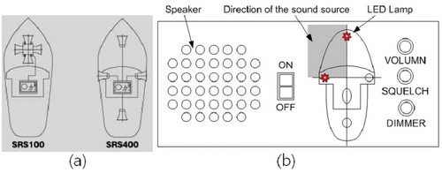
Many ships are heavy, and therefore it’s not easy for a ship to turn or stop like an automobile due to large inertia (Park et al. Citation2017). Every ship is equipped with radar which gives the information of other ships nearby (Kim, Lee, and Youn Citation2020). Nevertheless, there is a possibility of causing an accident due to poor visibility such as from dense fog or heavy rain (Joseph and Dalaklis Citation2021). For this reason, all vessels shall be subject to short sound (1s) and long sound (4 ~ 6s) to prevent a collision accident by attaching a sound generating device by IMO (International Maritime Organization) regulation (IMO resolution MSC.86(70) Citation1998; Sound Reception System Citation2021). As a device to support this, SRS (Sound Reception System) in has been developed and used for ships (Choi and Kim Citation2004; Roh, Do, and Lee Citation2011; Kim and Kim Citation2014). The SRS is composed of one speaker and four lamps. Four weatherproof microphones are mounted on the front, tail, and both sides of the ship and connected to the device. If two lamps are lit with speaker beeps, then the quadrant area of the two lamps is the direction of the sound. It provides one of four possibilities to the navigator as to the location of the acoustic source.
Figure 1. Resized image divided into 25 × 15 blocks (a) Positions of the SRS100 and SRS400 microphone units. (b) Panel in the ship’s bridge to show how to work the commercialized SRS. The second quadrant or the shaded area is the direction of the sound source
In this paper, we suggest a totally different SRS by a meta-lens known as an Acoustic Luneburg Lens (ALL). It is a gradient index lens which focuses the incoming wave on the opposite edge of the lens without aberration. It was suggested by Luneburg in the 1940’s and studied by Gutman in the 1950’s as a part of geometrical optics (Luneburg Citation1944; Gutman Citation1954) It was a typical model of transformation wave theory. The general solution of Luneburg lens was studied by Morgan (Morgan Citation1958). The basic methodology of the lens is as follows: One conjugate sphere is assumed to be outside the lens, while the other maybe either inside, outside, or at the surface. If one of the spheres is of infinite radius, then the lens will focus a parallel beam perfectly at a point on the other sphere.
There has been a lot of progress in the realization of ALL due to metamaterial technology. In 2014 an ALL has been realized by aluminium columns arranged in a cylindrical shape and at audible frequency range (1 ~ 7 kHz) (Kim S.-H., Citation2014). Since then, various research developments have been made by many researchers. (Wang et al. Citation2015; Zhu et al. Citation2017; Park and Lee Citation2018; Xie et al. Citation2018; Fu et al. Citation2018). The lenses are produced by 3D printers and operated at much higher frequencies.
ALL has two noble properties related with potential application areas. One is the focusing ability and the other is the directional ability. The focusing ability is useful for ultrasonic diagnosis in the biomedical or industrial fields because it extends the sensing range. The directional ability is useful for sonar because it gives the direction of the acoustic source directly. It works passively by the focusing of a sound wave, and actively by creating a plane wave at both modes. However, a direct application of the directional ability by ALL in industry has not been reported yet. We fabricated a two-dimensional ALL as SRS for ships and tested the directional ability on the sea. The result of the field experiment is reported.
Design and fabrication
A main feature of the Luneburg meta-lens is its multi-focusing property as shown in (Smolyaninova et al. Citation2015). The focusing region come from the geometry of the lens depends on the frequency. The refractive index of the ALL depends on the density of the medium. We designed and fabricated an ALL using the common gradient index lens method (Torrent and Sanchez-Dehesa Citation2007; Climente, Torrent, and Sanchez-Dehesa Citation2010; Kim S.-H., Citation2014). It is a direct geometric application of transformation optics. The refractive index profile of the Luneburg lens is given as, . Where R is the radius of the lens and
. It was derived from Fermat’s principle and the calculus of variation (Luneburg Citation1944; Gutman Citation1954; Morgan Citation1958). The refractive index of ALL can be rewritten in the discrete form as
, where N is the number of layers inside the lens and i =0,1, 2, …, N-1.
Figure 2. Numerical simulation of multi-focusing by Luneburg lenses with two sources of 90〫difference
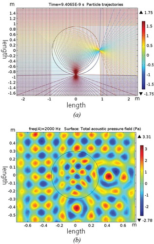
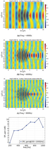
The ALL we manufactured is composed of 253 square cells and each cell has a high impedance cylindrical obstacle in the centre as in . We set the side length of the square cell be a = 10 cm and the number of concentric rings is N = 10. Then, the diameter of the lens is 180 cm. The obstacles are acrylic pipes of different radii and the same height of 20 cm. The lens of the top and bottom was covered by two large acrylic plates to satisfy the two-dimensional condition. The thickness plates and the pipes were 5 mm. The operational wavelengths of the lens for the focusing are in the range a ~ D, where D is the diameter of the lens. At the same time, the thickness of the lens or the height of the pipes, 20 cm, must be smaller than the wavelength due to the two-dimensional restriction, too. Then, the theoretical maximum focusing frequency range is about 200 ~ 1,700 Hz. However, the actual available frequency range is narrower than this. We plotted a numerical simulation of ALL at some frequency ranges by COMSOL Multiphysics, a finite element analysis and multi-physics simulation software (COMSOL Citation2021), in . The SPL (Sound Pressure Level) gain of 5 ~ 10 dB was obtained at 300 ~ 900 Hz.
Figure 3. The fabricated two-dimensional acoustic Luneburg lens made of 253 acrylic pipes of different radii. The diameter is 1.8 m
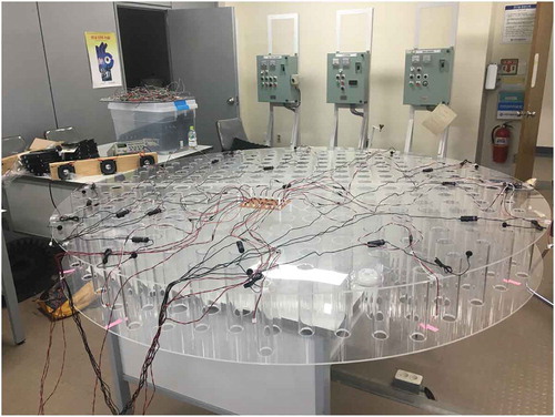
Figure 4. Numerical simulation of the 1.8 m acoustic Luneburg lens at different frequencies and their sound pressure level. (a) Freq. = 400 Hz, (b) Freq. = 600 Hz
Experiment on the sea
We have tested the SONAR-like focusing ability of the ALL with a ship’s horn sound a couple of years ago (Jang, Kim, and Ahn Citation2018). The ship is docked and ALL was fixed on land. Then, the lens focused the incoming sound enough to recognize up to 1.4 km away from the source without any other noise. At the distance of more than 1 km, lower than 200 Hz was the main source from the horn. However, the real condition at sea is totally different from this. Sound sources are possibly multiple and emitters and receiver are both moving. It is pretty dynamic and confusing with a lot of noises.
Therefore, we decided to test the focusing ability of the ALL at sea where both are moving. The air horn of the university training ship of the Mokpo National Maritime University, about 4,700 tons, was used as a soun source. Four people with the lens boarded a small boat to control the lens as . During the loading of the lens to the boat, the acrylic edge of the ALL was broken a little. Eight microphones were installed at the edge of the lens with the same intervals of 45 degrees. Eight is the minimum number of the microphones to check the operation, and it is adjustable to as many as we need. The microphones are connected to the laptop and operated by LabVIEW program.
Figure 5. Installing the microphones to the ALL on the boat. The edge of the ALL was broken a little during the loading
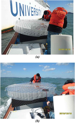
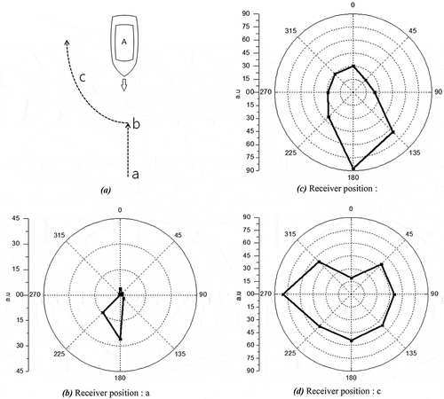
The experiment was carried out in the Yellow Sea near 34.47.0 N and 126.15.0E on the morning on 16th of December 2018. The sky was clear and the temperature was about 3 ~ 5 Celsius. The training ship and boat were sailed at 20 ~ 40 knots (37 ~ 54 km/h), and the distance between the two were about 300 ~ 700 m. Two vessels moved a similar way of collision situation as . The distance of more than 1 km was too weak to recognize the source signal with the lens. To detect far distances, it needed a wider lens. Since we need low frequencies to predict the exact direction, we filtered the high-frequency noises of the sound source. Several Micro-Electro Mechanical Systems microphones ADMP401 were used to convert sound signal into an electrical signal.
Figure 6. The trajectory of the two vessels and the data depending on the positions. A is the emitter and a, b, c are the receiver positions. This is not the real scale. The distances between the two vessels are (b) ~700 m, (c) ~ 300 m, and (d) ~ 300 m. The round points of 1–8 are the directions. The bar numbers are the intensities of arbitrary units
Summary and discussion
A two-dimensional acoustic meta-lens with a diameter of 180 cm was used as a sound reception system for a ship. The design and performance of the lens as a sound reception system was reported. The directional ability was measured under dynamic condition that the source and receiver were moving at sea. We tested the performance of the ALL made of acrylic in the air, but it should be made of metal of large acoustic impedance for underwater detection. It directly indicated the direction of sound sources with much better accuracy than the commercialized SRS devices on the market. If it is commercialized, a monitoring system of the mirror image can be installed in the navigation room or combined with RADAR. Then, the motion of the acoustic source can be observed directly by the naked eye and ear. Applying multiple lens system, we can predict the distance from the sound source to the receiver in real-time.
Although the meta-lens type SRS of the diameter of 180 cm worked in the sound frequency range of 300 ~ 900 Hz, it cannot satisfy the IMO regulation which requires to accept the range of 70 ~ 820 Hz (IMO resolution MSC.86(70) Citation1998). To satisfy the regulation, the diameter of the meta-lens should be 5 m at least, but it occupies a huge space. This difficulty could be overcome through some geometrical transformation or modification such as elliptical or box-type thin lens (Dyke et al. Citation2014; Gao et al. Citation2018; Zhao et al. Citation2020) may applicable. Another practical concept is foldable lens like wings of insects that expand only during bad weather conditions.
Disclosure statement
The named authors have no conflict of interest, financial or otherwise.
References
- Choi, J. W., and K. J. Kim. 2004. “A New Sound Reception System Using A Symmetrical Microphone Array and Its Numerical Simulation.” Journal of Ship & Ocean Technology 8 (3): 18–25.
- Climente, A., D. Torrent, and J. Sanchez-Dehesa. 2010. “Sound Focusing by Gradient Index Lenses.” Applied Physics Letters 97 (10): 104103 (1–3). doi:10.1063/1.3488349.
- COMSOL. “A Multi-physics Simulator.” Accessed 12 January 2021. https://www.comsol.com/acoustics-module
- Dyke, A., H. Dyke, S. Haq, and Y. Hao. 2014. “Flat Luneburg Lens via Transformation Optics for Directive Antenna Applications.” IEEE Transactions on Antennas and Propagation 62 (4): 1945–1953. doi:10.1109/TAP.2014.2302004.
- Fu, Y., J. Li, Y. Xie, C. Shen, Y. Xu, H. Chen, and S. A. Cummer. 2018. “A Compact Acoustic Retroreflector Based on A Mirrored Luneburg Lens.” Physical Review Materials 2: 105202 (1–7).
- Gao, J., C. Wang, K. Zhang, Y. Hao, and Q. Wua. 2018. “Beam Steering Performance of Compressed Luneburg Lens Based on Transformation Optics.” Results in Physics 9: 570–575. doi:10.1016/j.rinp.2018.01.016.
- Gutman, A. S. 1954. “Modified Luneburg Lens.” Journal of Applied Physics 25 (7): 855–859. doi:10.1063/1.1721757.
- IMO resolution MSC.86(70). Adoption of new and amended performance standards for navigational equipment. December 1998. “SOLAS Chapter V. Safety of Navigation, REGULATION 19, Carriage Requirements for Ship Borne Navigational Systems and Equipment. ISO 14859:2012 - Ships and Marine Technology Sound Reception Systems.” Accessed 12 January 2021. https://www.iso.org/obp/ui/#iso:std:iso:14859:ed-1:v1:en.https://www.iso.org/standard/55195.html
- Jang, H., S.-H. Kim, and B.-W. Ahn. 2018. “Sound Reception System for a Ship by an Acoustic Lens, J.” Korean Society of Marine Engineering 42 (3): 191–196.
- Joseph, A., and D. Dalaklis. 2021. “The International Convention for the Safety of Life at Sea: Highlighting Interrelations of Measures Towards Effective Risk Mitigation.” Journal of International Maritime Safety, Environmental Affairs, and Shipping 5 (1): 1–11. doi:10.1080/25725084.2021.1880766.
- Kim, H., and J. Kim. 2014. “A Study on Digital Sound Reception Systems for Ships.” Journal of the Korean Society of Marine Engineering 38 (9): 1125–1130.
- Kim, I., S. Lee, and I. Youn. 2020. “Adopting the Audible Alert System for the Electronic Chart Display and Information System for Improvement of Early Navigational Situation Awareness.” Journal of International Maritime Safety, Environmental Affairs, and Shipping 4 (4): 177–186. doi:10.1080/25725084.2020.1861825.
- Kim, S.-H. 2014. Cylindrical Acoustic Luneburg Lens, 8th International Congress on Advanced Electromagnetic Materials in Microwaves and Optics (Metamaterials), IEEE Xplore, 364–366. Copenhagen, Denmark.
- Luneburg, R. K. 1944. Mathematical Theory of Optics. Rhode Island: Brown Univ. Luneburg Sonar demonstration in the lab. Accessed 12 January 2021. https://youtu.be/RVuaeGGwMZY,https://youtu.be/jPzrMC7wG3I,https://youtu.be/l45DwmL80Uc
- Morgan, S. P. 1958. “General Solution of the Luneburg Lens Problem.” Journal of Applied Physics 29 (9): 1358–1368. doi:10.1063/1.1723441.
- Park, C. M., and S. H. Lee. 2018. “Acoustic Luneburg Lens Using Orifice-type Metamaterial Unit Cells.” Applied Physics Letters 112: 074101 (1–4). doi:10.1063/1.5016477.
- Park, Y., J. Park, M. Lee, and S. Park. 2017. “Application of Potential Assessment of Risk (PARK) Model in Korea Waterway.” Journal of International Maritime Safety, Environmental Affairs, and Shipping 1 (1): 1–10. doi:10.1080/25725084.2017.1412916.
- Roh, C. S., S. C. Do, and J. S. Lee. 2011. “Study on Location Estimation of Nearby Ships from Whistle Blast (1).” The Journal of the Korea Institute of Electronic Communication Sciences 4 (1): 32–38.
- Smolyaninova, V. N., D. Lahneman, T. Adams, T. Gresock, K. Zander, C. Jensen, and I. I. Smolyaninov. 2015. “Experimental Demonstration of Luneburg Waveguides.” Photonics 2 (2): 440–448. doi:10.3390/photonics2020440.
- Sound Reception System. Accessed 12 January 2021. https://cirspb.ru/en/equipment-and-service/sound-reception/.http://www.omegain.com/SOUND-RECEPTION-SYSTEM.https://www.pacatlantic.com/zollner/productcategory/sound-reception-systems/.https://www.mackaycomm.com/products/communication/soundreceptionsystems/zenitel-vingtor-sound-reception-system-vss-2/.https://www.zenitel.com/product?system=122.https://www.phontech.net/about/phontech-communication-systems
- Torrent, D., and J. Sanchez-Dehesa. 2007. “Acoustic Metamaterials for New Two-dimensional Acoustic Devices.” New Journal of Physics 9 (9): 323 (1–13). doi:10.1088/1367-2630/9/9/323.
- Wang, C. F., C. N. Tsai, I. L. Chang, and L. W. Chen. 2015. “Wideband Acoustic Luneburg Lens Based on Gradient Index Phononic Crystal.” Proceedings of the ASME 2015 International Mechanical Engineering Congress and Exposition IMECE2015–52927.
- Xie, Y., Y. Fu, Z. Jia, J. Li, C. Shen, Y. Xu, H. Chen, and S. A. Cummer. 2018. “Acoustic Imaging with Metamaterial Luneburg Lenses.” Scientific Reports 8: 16188 (1–6). doi:10.1038/s41598-018-34581-7.
- Zhao, L., E. Laredo, O. Ryan, A. Yazdkhasti, H.-T. Kim, R. Ganye, T. Horiuchi, and M. Yu. 2020. “Ultrasound Beam Steering with Flattened Acoustic Metamaterial Luneburg Lens.” Applied Physics Letters 116: 071902 (1–5). doi:10.1063/1.5140467.
- Zhu, R., C. Ma, B. Zheng, M. Y. Musa, L. Jing, Y. Yang, H. Wang, S. Dehdashti, N. X. Fang, and H. Chen. 2017. “Bifunctional Acoustic Metamaterial Lens Designed with Coordinate Transformation.” Applied Physics Letters 110: 113503 (1–5). doi:10.1063/1.4978689.