
ABSTRACT
As the improvement of ship energy efficiency is emphasized internationally, researches for this are being conducted in various ways. Accordingly, research is being conducted on the application of ORC power generation systems for ships using waste heat from the main engine exhaust gas generated during operation. The WHRU constituting the ORC system must be designed so that stable-phase change heat transfer occurs. In this study, a design study was conducted using the ANSYS CFX program for the production of a WHRU capable of generating ORC power generation output for a 30-kW ship using R134a refrigerant. A WHRU capable of achieving 30 kW generation output performance was designed while changing various design elements (shape, tube diameter, number of tubes, number of stages, etc.) of the WHRU. As a result, it was confirmed that the refrigerant (R134a) in a liquid state at a temperature of 14.8°C entered at a flow rate of 1.06 kg/s, evaporated by the exhaust gas, and was discharged from the outlet in a state of vapor fraction 1 at a temperature of 56.4°C. The heat transfer rate of the WHRU was 219.2 kW, the pressure during the evaporation process was constant at 13.9 bar in absolute pressure, and the enthalpy was 220 kJ/kg at the inlet and 426 kJ/kg at the outlet, respectively.
Introduction
The International Maritime Organization (IMO) is discussing various international regulations to reduce greenhouse gases generated in the international shipping industry and to improve ship energy efficiency to reduce carbon intensity.
At the 76th Marine Environment Protection Commission (MEPC) meeting held in 2021, it was decided to implement the Energy Efficiency Existing Ship Index (EEXI) regulation for ships currently operating from 1 November 2022 (E.-J. Kim, Citation2018).
The development of regulations for existing operating vessels means that an international consensus has been formed on the demand for energy efficiency improvement targeting operating vessels, unlike the existing EEDI regulations for newly built vessels.
In order to improve the energy efficiency of ships, research on the development of an organic Rankine cycle (ORC) system for ships using waste heat from exhaust gases generated from propulsion engines is being conducted. As a representative study, Moon et al. (Citation2021) simulated ORC performance using waste heat generated from the ship’s propulsion engine and seawater used for cooling in the ship and reviewed the appropriate operating pressure to derive the maximum net output (Moon et al., Citation2021). Girgine (Citation2017) simulated an ORC system using waste heat generated from a 1000-kW power generation engine of a warship and examined the effect of reducing approximately 67 tons of carbon dioxide and the economic effect of fuel savings (Girgin & Ezgi, Citation2017).
As reviewed in the previous study, the ORC power generation system configuration using exhaust gas waste heat generated from the main engine of the ship is an energy efficiency improvement method that can be applied to ships currently operating if appropriate operating conditions are met.
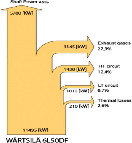
The approximate energy balance of ship propulsion is shown in (Marpol 73/78 Annex VI, Citation2005). About 50% of the lower heating value (LHV) of fuel is used for ship propulsion, and the remaining energy is wasted in the form of heat. Therefore, if the exhaust heat discarded to the outside is recovered through an appropriate system, the energy efficiency of the entire system can be improved. A waste heat recovery system (WHRS) is a useful technology in this respect.
Figure 1. Energy balance of the engine W6L50DF.
The final purpose of this study is to manufacture a WHRU that can be applied to a 30-kW ORC power generation system for ships. Through this design study, the shape of the tube to be actually used for manufacturing and the shape of the WHRU exterior were determined, and based on this, CFD modeling was produced using ANSYS CFX (v.18.1), a commercial numerical analysis program. Then, while adjusting various variables of CFD modeling, the design requirements of the WHRU to achieve the target performance were derived.
This design study is a follow-up study of the 500-kW class WHRU development conducted in 2021 (Hwang et al., Citation2021). show the components of the ORC system and the actual manufactured WHRU product based on previous design studies. In this paper, the heat transfer performance characteristics were reviewed through CFD modeling of a WHRU that can be used in an ORC power generation system with a 30-kW output.
Figure 2. ORC generation system with a total generation output of 30 kW and a WHRU of 150 kW.
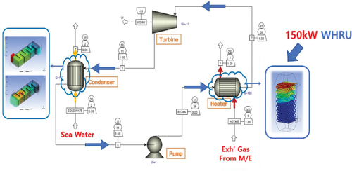
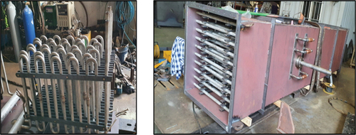
Figure 3. Production process of WHRU.
Modelling
WHRU modeling
The steel tube for the heat exchanger used to manufacture the WHRU has an outer diameter of 31.75 mm, a thickness of 2.769 mm, and an inner diameter of 26.213 mm, and has a thermal conductivity of 60.5 W/m·K.
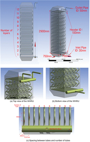
shows the modeling shape of the waste heat recovery unit (WHRU) developed through this study. shows the detailed figures of each modeling part. The tube constituting the WHRU was modeled based on the inner diameter (26.213 mm) without shaping the thickness itself. This is because calculation itself is difficult because an excessive number of meshes are required in the process of creating a mesh when producing a small tube thickness shape.
Table 1. Dimensions of each part of the WHRU.
Figure 4. CFD modeling of WHRU.
The CFX program provides a function that simulates the heat transfer performance according to the tube thickness by inputting the tube thickness and physical properties in the tube-type heat exchanger calculation. In the modeling calculation, this function was used to calculate the heat transfer characteristics according to the pipe thickness.
The inside diameter of the inlet pipe of the refrigerant is designed to be slightly smaller than the outlet. A phase change occurs in this heat exchanger. Therefore, the refrigerant in the liquid state enters and is changed to the gaseous state through heat exchange with the exhaust gas, and then discharged through the outlet. The R134a refrigerant used in the calculation shows the density of 1146.1 kg/m2 for liquid and 50.072 kg/m2 for gas under the operating pressure of 10 bar (absolute pressure). Therefore, when the refrigerant flows at the same mass flow rate at the inlet and outlet, the velocities are different. Therefore, the diameter of the refrigerant inlet pipe is designed to be slightly smaller than that of the outlet for proper fluid velocity.
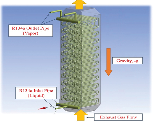
shows the WHRU modeling and the flow direction of the working fluid. The exhaust gas flows upward from the bottom of the WHRU, and the liquid refrigerant flows from the bottom to the top. Two outlet pipes were installed. In order for the refrigerant in liquid state to flow through the inlet at the same flow rate through the 10 tubes inside the heat exchanger, orifices of different sizes must be installed at the inlet of the tube. However, since the orifice was not applied to the pipe inlet in the same modeling, the same rate of heat transfer did not occur in the 10 pipes. Therefore, two pipes were installed at the outlet of the 10 pipes to ensure balanced heat transfer. If one pipe is installed at the pipe outlet, more heat transfer area is expected to be required for the same heat transfer performance.
Figure 5. Working fluid and exhaust gas flow gas flow in modeling.
Meshing
The mesh used for this analysis was meshed using a tetrahedral type mesh, which is an unstructured mesh. The program used to generate the mesh was the ANSYS Meshing program of ANSYS company. The ANSYS Meshing program can configure both structured and unstructured meshes. There are two things to check the number of grids, which are Elements and Nodes. The CFX solver used in this analysis is a node-based solver, and calculation information is stored in the node. The total number of nodes used in this analysis is 1380,243 and the number of elements is 8081,996.
Boundary condition
summarizes the values of the boundary conditions and the results of the calculation. This flow analysis simulated the process in which the liquid refrigerant (R134a) flowing into the WHRU by the exhaust gas is evaporated and discharged in a saturated vapor state. As the refrigerant flows upward inside the WHRU, a phase change occurs. During operation, the gas and liquid states coexist inside the WHRU, so the liquid and gas properties of the refrigerant were applied together for the simulation calculation. As the working fluid, R134a refrigerant, which has been confirmed to have high chemical stability and eco-friendly performance in several studies, was selected (Cho & Cho, Citation2015; J.-S. Kim et al., Citation2015).
Table 2. Numerical analysis calculation conditions and results.
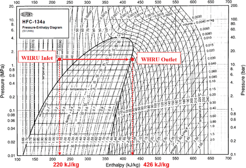
shows the simulation calculation results on a Mollier diagram. In the phase change from liquid to gas that occurs inside the WHRU, refrigerant in liquid state with a temperature of 14.8°C enters from the tube inlet, exchanges heat, and is discharged in gaseous state. At this time, the enthalpy at the inlet was 220 kJ/kg and the enthalpy at the outlet was 426 kJ/kg.
Figure 6. Phase change of working fluid (R134a) on Moliere diagram.
Performance characteristics of the WHRU
Temperature characteristics
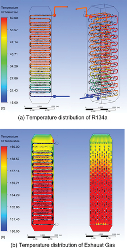
shows the temperature distribution of the refrigerant (R134a) for the temperature range of 15–60°C in the horizontal section of the WHRU. The temperature change in the section where R134a refrigerant at a temperature of 15°C flows into the WHRU in a liquid state and changes to a saturated vapor state after heat exchange can be confirmed. In the section where the phase change occurs, the temperature of the refrigerant is constant at 56.4°.
Looking at the temperature distribution of the header part where gas gathers in the upper area of the WHRU, it can be seen that it is somewhat uneven. This occurs because the heat transfer characteristics of the 10 tubes in the WHRU are not the same. If only one outlet pipe is installed, the temperature distribution will be more uneven. It is considered necessary to adjust the method of arranging the cold outlet pipe of the WHRU so that a uniform flow rate flows through the 10 pipes inside the WHRU. Insertion of an orifice into the tube inlet may be considered.
Pressure characteristics
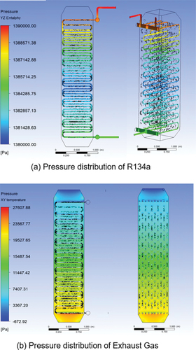
shows the pressure distribution of the refrigerant in the horizontal section of the WHRU. The pressure appears uniform throughout, with an approximate absolute pressure of 13.9 bar. It can be seen that there is a slight pressure change due to the flow and phase change of the refrigerant inside the WHRU, but the pressure is generally maintained at a constant level.
The pressure on the exhaust gas side shows an inlet pressure of 20.4 kPa and an outlet pressure of 0.65 kPa. The differential pressure is 201.4 mmH2O, and when installed on a ship, the effect on the back pressure on the exhaust gas side of the main engine is insignificant. This is the calculation result of the staggered arrangement of the single 12-stage tubes, and it must be designed so that the differential pressure does not adversely affect the operation of the main engine due to changes in the exhaust gas flow rate and pipe arrangement design inside the heat exchanger.
Figure 7. Temperature distribution.
Velocity characteristics
shows the velocity distribution of the refrigerant in the WHRU. A constant mass flow in the WHRU does not necessarily mean constant velocity. Since the density of the refrigerant changes according to the phase change within the WHRU, the velocity in the gaseous region is relatively higher than in the liquid state, and the velocity distribution is slightly lower in the liquid state.
The region where the velocity of the refrigerant is the highest is the exit region, where a velocity of about 5.5 m/s is shown. In the section where the refrigerant is in a liquid state, it shows a speed of about 0.6 m/s. This difference in velocity appears in proportion to the ratio of the density according to the state of the fluid at the same pressure.
Figure 8. Pressure distribution.
Vapor fraction characteristics
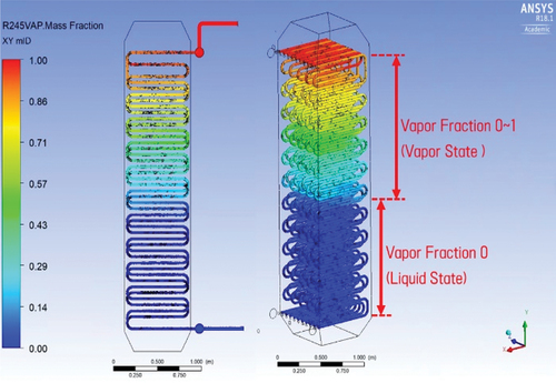
shows the vapor fraction of the refrigerant that changes according to the phase change occurring inside the WHRU. As the inlet boundary condition, the vapor fraction of the refrigerant observed at the inlet is 0 because the boundary condition is set so that the liquid refrigerant of zero vapor fraction enters. It can be seen that the vapor fraction increases as the refrigerant starts to change into a gaseous state near the middle of the waste heat recovery device from the inlet. In the outlet area, it shows a vapor fraction of 1 as saturated steam.
Figure 9. Velocity distribution.
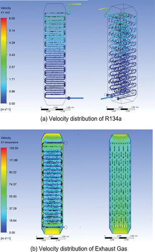
Figure 10. Vapor fraction distribution.
Conclusion
This numerical analysis is a heat flow analysis for a waste heat recovery unit (WHRU) as an element technology in an ORC-based power generation system that uses exhaust gas discharged from a ship’s main engine as a source of heat energy and refrigerant R134a as a working fluid. This was done through the ANSYS CFX (v.18.1) program. While changing the design elements (shape, pipe diameter, number of pipes, number of stages, etc.) of the waste heat recovery device to be developed, a WHRU capable of achieving 30 kW power generation output performance was designed. As a result, the following conclusions were obtained within the subject of this analysis and the calculation conditions and scope.
It was confirmed that the refrigerant (R134a) in a liquid state at a temperature of 14.8°C entered at a flow rate of 1.06 kg/s, evaporated by the exhaust gas, and was discharged from the outlet in a state of vapor fraction 1 at a temperature of 56.4°C. The heat transfer rate of the WHRU was 219.2 kW, the pressure during the evaporation process was constant at 13.9 bar in absolute pressure, and the enthalpy was 220 kJ/kg at the inlet and 426 kJ/kg at the outlet, respectively.
In the WHRU, exhaust gas enters from the bottom and is discharged from the top. Under the conditions of exhaust gas flow rate of 34 kg/s and inlet temperature of 160°C, the pressure difference between inlet and outlet was 201.4 mmH2O. The exhaust gas flow rate and temperature used in the simulation are conditions considering the actual test operation situation of the WHRU, and it should be taken into account that the exhaust gas temperature of the operating ship is actually higher than 160°C.
One inlet pipe was installed at the refrigerant inlet and two pipes were installed at the outlet. This is a measure to ensure a uniform flow of refrigerant is distributed to the 10 tubes installed inside the WHRU. In this design study, a uniform flow distribution was attempted by installing two outlet pipes in a balanced way, but since this is associated with an increase in manufacturing cost, it is necessary to review other methods that can adjust the flow rate, such as inserting an orifice in the pipe, depending on the manufacturing situation.
Disclosure statement
No potential conflict of interest was reported by the author(s).
Additional information
Funding
References
- Cho, S.-Y., & Cho, C.-H. (2015). Effect on the cycle by the properties of working fluids using organic Rankine cycle. The KSFM Journal of Fluid Machinery, 18(4), 1–6. https://doi.org/10.5293/kfma.2015.18.4.005
- Girgin, I., & Ezgi, C. (2017). Design and thermodynamic and thermoeconomic analysis of an organic Rankine cycle for naval surface ship applications. Journal of Energy Conversion and Management, 148, 623–634. https://doi.org/10.1016/j.enconman.2017.06.033
- Hwang, D.-J., Park, S.-K., Jee, J.-H., Band, E.-S., & Oh, C. (2021). A study on the thermal flow of Waste Heat Recovery Unit (WHRU) for ship’s organic Rankine cycle power generation system using CFD method. Journal of the Korean Society of Marine Environment & Safety, 27(5), 647–655. https://doi.org/10.7837/kosomes.2021.27.5.647
- Kim, E.-J. (2018). A study on the improvement plans of the IMO’s regulation for the greenhouse gas emissions from international shipping. Journal of Regional Industry Review, 41(1), 237–260. https://doi.org/10.33932/rir.41.1.12
- Kim, J.-S., Kim, D.-Y., Kim, Y.-T., & Kang, H.-K. (2015). Performance analysis of an organic Rankine cycle for ocean thermal energy conversion system according to the working fluid and the cycle. Journal of the Korean Society of Marine Engineering, 39(9), 881–889. https://doi.org/10.5916/jkosme.2015.39.9.881
- Marpol 73/78 Annex VI. (2005). Regulations for the prevention of air pollution from ships. International Maritime Organization.
- Moon, J.-H., Lee, H.-S., & Seo, J.-B. (2021). Performance analysis of ORC cycle using waste heat. Journal of Power System Engineering, 25(5), 45–50. https://doi.org/10.9726/kspse.2021.25.5.043