
 ?Mathematical formulae have been encoded as MathML and are displayed in this HTML version using MathJax in order to improve their display. Uncheck the box to turn MathJax off. This feature requires Javascript. Click on a formula to zoom.
ABSTRACT
Metal-based electromagnetic interference shielding materials are limited in their application due to their susceptibility to corrosion. They are therefore being replaced by corrosion-resistant polymers and carbon nanotubes. However, it is difficult to disperse carbon nanotubes within polymer matrices as they aggregate because of van der Waals forces. Therefore, to improve the dispersion of carbon nanotubes, we modified thin-wall carbon nanotubes with flavin mononucleotides and tested them by manufacturing a polymer composite. Nylon 12 was chosen as the polymer matrix owing to its excellent abrasion resistance and low wettability. Furthermore, upon annealing the modified carbon nanotubes, the tensile strength of the composite and dispersion after modification increased. When 10 wt% of the annealed modified nanotubes was used, the composite exhibited a sheet resistance of 8.7 Ω/sq and an EMI shielding effectiveness of 29.4 dB in the X-band. The novel composite can be advantageous for use in electronic equipment due to its low weight and flexibility.
GRAPHICAL ABSTRACT
1. Introduction
Electromagnetic waves interfere with the functioning machines through conduction or emission, leading to noise and shortening of the equipment lifespan, eventually leading to reduced efficiency of the machine.[Citation1] In addition, electromagnetic waves negatively affect human health: when the human body is exposed to electromagnetic waves, the nervous system is stimulated, and in severe cases, heart attacks can occur.[Citation2] Therefore, there is a need for electromagnetic interference (EMI) shielding materials. Such materials are generally manufactured using metals; however, their application is limited because they are heavy, difficult to process, and susceptible to corrosion. Conductive polymers have therefore been widely investigated as a replacement for metal-based EMI shielding materials because they are lighter, easier to process, and more resistant to corrosion. EMI shielding by dispersing conductive nano-fillers in polymer matrices has also been extensively studied.[Citation3,Citation4]
In order to measure EMI, the material must be both magnetic and dielectric, capable of reflection and absorption.[Citation5] To solve this problem, recently, polymers have been blended with conductive materials such as carbon nanotubes (CNT) and graphene to produce EMI shielding polymer composite films.[Citation6–8] In a previous study, researches on compounding polymers and conductive nano-fillers were widely conducted. There is a study that lowers the percolation threshold and enhances conductivity and mechanical properties by making a conductive composite material with PA12, Graphene, and POE-g-M by melt compounding method with a low percolation threshold of 0.3 vol % and 6.7 × 10⁻² S/m. Similarly, some investigations are executed to improve conductivity using a multi-wall carbon nanotube.[Citation9,Citation10] Additionally, studies have been done on the creation of conductive polymers using polypropylene (PP) and CNTs with 8 × 10⁻² S/m. Li, Xing-Hua et al. examined the enhancement of conductivity and impact strength by altering CaCO3, an inorganic nanoparticle, and mixing it with PP/CNT in order to improve the lower moduli.[Citation11]
Fe/CNT was prepared by Chea and coworkers using slurry sheet; however, when the content of CNTs exceeded 2 wt%, the dispersion was affected and EMI shielding could thus not be performed.[Citation12] Moon and team had fabricated CF/PA6 and PC/ABS composites with an EMI shielding effect (SE) of 15 dB and 12 dB, respectively, at 10 wt% of conductive filler.[Citation13] Liu and team reported PU composite films with 20 wt% of SWCNT exhibiting EMI SE of 17 dB.[Citation14] In classical works, EMI shielding measures between 150 MHz to 1.5 GHz frequency region; however, in the current advanced society, several electronic apparatuses are used in the X-band region (8.2 GHz to 12.4 GHz), as well as in low-frequency bands.[Citation14,Citation15]
Numerous studied have modified CNTs using various organic and inorganic materials[Citation16] to improve their EMI properties. Such modification is usually conducted through reforming, which includes chemical reforming using a strong acid and mechanical reforming using physical adsorption. Originally, CNT was modified with a carboxyl group, specifically with COOH. However, these experiments use strong acids, which may pose a risk to CNT.[Citation17–19] It may damage the conjugate structure of CNTs, and thus the dielectric constant can be lowered.
In this study, we fabricated composites of nylon 12 and modified-CNTs to test their performances as EMI shielding materials. Nylon 12, was chosen as the matrix material owing to its low moisture absorption, as well as it having the best abrasion resistance among the nylon series.[Citation20] The CNTs were modified with flavin mononucleotide (FMN) using a physical adsorption method[Citation21] CNTs were modified by wrapping them pentadienyl groups through repulsive force; pentadienyl groups are hyper-conjugated to each other, resulting in improved conductivity.[Citation21–23] Furthermore, a group of the modified CNTs also went annealing to test their EMI shielding properties when dispersed through the composite. Finally, the composites of CNTs and nylon 12 were fabricated through melt blending and hot pressing with 5, 7.5, and 10 wt% content of carbon nanotubes and modified carbon nanotubes.
2. Materials and methods
2.1. Materials
8A thin wall carbon nanotubes (CNTs) (diameter: 4–9 nm, number of walls: 3–7, purity >98.5 wt%) were obtained from JEIO Co., Ltd. (Ansan, Korea). Riboflavin 5’-Monophosphate Sodium (FMN, assay 73–79) was purchased from Wuhan Fortuna Chemical Co., LTD. (Wuhan, China). The nylon 12 (Polyamide 12, AM376045, particle size distribution D50: 90 μm) was purchased from Goodfellow (London, United Kingdom). Deionized water was prepared in the laboratory.
2.2. Preparation of modified CNTs
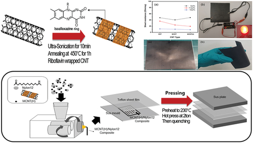
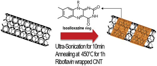
5 g of CNT was homogeneously dispersed within 4 g of FMN in 300 ml deionized water at 25°C via ultrasonication for 10 min. The mixture was then vacuum filtered and freeze dried to obtain MCNTs. In addition, MCNTs underwent annealing in a furnace at 450°C for 1 h to obtain annealed MCNTs (), which will henceforth be referred to as MCNT(H)s
Figure 1. CNT modification with flavin mononucleotide.
2.3. Preparation of polymer composite with MCNT series and nylon 12
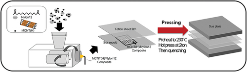
The different types of CNTs and nylon 12 were mixed via melt blending at 230°C at 60 rpm using a twin-screw extruder. The composite was then placed in a square sus mold, preheated to 230°C for 20 min, and then hot-pressed with 2 tons of force for 20 min to obtain the composite films (). The composites of nylon 12 with 5, 7.5, and 10 wt% CNT have been abbreviated to CNT 5, CNT 7.5, and CNT 10, respectively. The nylon 12 composites containing MCNT and MCNT(H) were also similarly manufactured and abbreviated.
Figure 2. Schematic illustration of preparation procedure of the MCNT(H)-nylon12 composite film.
2.4. Characterization
Zeta Potentiometer (ELSZ −1000) was used to characterize the dispersion of CNT, MCNT and MCNT(H). Thermogravimetric analysis (TGA) was performed with a TA instrument (Q500, USA) under a nitrogen atmosphere; for the analysis, 5 mg of the CNT series was heated at a heating rate of 20°C/min from 25 to 800°C. The cross-section morphologies of the composite films were observed using a field emission scanning electron microscope (FESEM, SU − 8010, Hitachi, Japan). The mechanical properties of the composite films were investigated according to ASTM D 882 using a universal testing machine (UTM, Instron 3342, USA). Specimens of the sample film were of the size 20 × 100 mm. The sheet resistance was measured using a non-contact sheet resistance meter (TP lab 2020, SARAGUS, Germany). The specimen of the sample was manufactured in a rectangular shape with a size of 100 × 100 mm, and was measured using a non-contact measuring instrument of SRAGUS. Samples were measured 10 times at ambient temperature. The electrochemical impedance spectroscopy (EIS) analysis were performed with ZIVE sp2 (Wonatech, Korea), and electromagnetic interference (EMI) was measured using Network Analyzer E8364B (Agilent, USA).
3. Results and discussion
3.1. Characterization of modified CNT
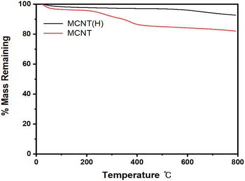
According to the TGA results (), the mass of MCNTs decreased at 290 and 450°C, which correspond to the dihydroxylation and dephosphorylation, respectively, of the d-ribityl phosphate. In contrast, a decrease in the mass of MCNT(H)s occurred at around 60°C, revealing that dephosphorylation had already occurred during the annealing process, which led to dehydration and evaporation. The results therefore verify that FMN was adsorbed on the MCNTs and MCNT(H)s. Additionally, it was determined that the thermal stability of MCNT and MCNT(H) was improved.[Citation21]
Figure 3. Thermogravimetric analysis (TGA) of MCNT and MCNT(H).
The results of zeta potential measurement are shown in . At a zeta potential value of −10 mv, the CNTs try to coagulate with each other due to the van der walls force. The dispersibility is good when it falls within the range of − 40 and −60 mv. This is as a result of the CNT-wrapped FMN being forced out by a repulsive force.[Citation24] Thin wall CNTs have good conductivity and dispersibility, and are sufficient to replace single walls. However, MCNT dispersibility is not good because CNT and FMN play separately unless annealing is performed when modified with FMN. If the FMN wraps around the CNT by annealing, a repulsive force is generated and the dispersibility is improved. It can be seen that the conductivity value of CNT is improved as it is modified to 0.0033 mS/cm, MCNT 0.0044 mS/cm, and MCNT(H) to 0.0049 mS/cm, respectively.
Figure 4. (a) Zeta potential distribution of CNT, MCNT, MCNT(H) in 0.1 wt% in ethanol (b) Zeta potential and electrical conductivity (c) aqueous distribution of CNT after sonication.
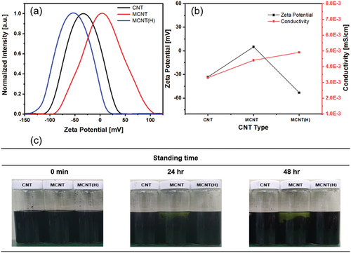
MCNT(H)s had the best dispersibility but the lowest conductivity (). However, the difference in conductivity is negligible, as the values of the conductivity are low. In addition, CNTs, MCNTs, and MCNT(H)s were dispersed in ethanol at a concentration of 0.1 wt% for 1 h under ultra-sonication. Photographs were taken after duration of 0 min, 24 h, and 48 h, and it was observed that CNTs were and MCNT(H)s were well-dispersed; in contrast, MCNTs aggregated. Therefore, we could conclude that the FMN wrapped around the CNTs, creating a repulsive force between them that prevented aggregation and promoted dispersing.
3.2. Characterization and properties of CNT-nylon12 composite film
The cross-sectional image of the MCNT-nylon 12 composite film is shown in . It can be observed from the morphology of the composite film that the CNTs were well-dispersed throughout the nylon 12 matrix. Although the distance between the CNTs depended on their content in the composite, the tendency to aggregation did not increase with increasing CNT content. Therefore, the CNT successfully dispersed in the nylon 12 matrix.
Figure 5. SEM images of composite film (a) CNT 5 wt%, (b) CNT 7.5 wt%, (c) CNT 10 wt%, (d) MCNT 5 wt%, (e) MCNT 7.5 wt%, (f) MCNT 10 wt%, (g) MCNT(H) 5 wt%, (h) MCNT(H) 7.5 wt% (i) MCNT(H) 10 wt%.
lists the mechanical properties of the CNT and nylon 12 composite films. The elongation of the composites shows the lowest value 4.5% at 5 wt% CNT content. Modulus can be confirmed to be the lowest at 296.1 MPa. It was observed that the higher the MCNT(H) content, the lower the elongation and the higher the modulus value. The tensile properties tended to increase with decreasing MCNT content. This is because, as the content of MCNTs increases between nylons, FMN reacts with oxygen in the air inside the nylon matrix and dehydrogenases through oxidation/reduction reactions, which interferes with the binding of nylon. At 10 wt% of MCNT(H), the modulus was the highest at 452 MPa, and the tensile strength gradually decreased, which is similar to the 5 wt% composite.
Table 1. According to CNT contents mechanical properties of composite film.
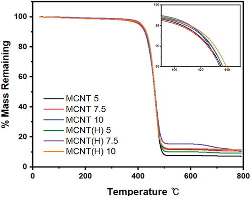
The TGA data of the composite films are shown in . The slight loss in mass at around 100°C for all the composites is attributed to the evaporation of absorbed water. It is expected that the loss in mass that occurred between 100–300°C was due to the removal of oxygen-containing groups on the surface. In other words, a slight decrease in mass occurs because the moisture inside the nylon evaporates. The weight loss of the composite films increased with increasing MCNT content; and using MCNT(H).
Figure 6. Thermogravimetric analysis (TGA) of MCNT and MCNT(H)-nylon composite film.
A non-contact sheet resistance meter was used to measure the sheet resistance of the composite films; the results are shown in and . 5 wt% CNT had the highest resistance value of 47.3 Ohm/sq, and 10 wt% MCNT(H) had the lowest resistance value of 8.7 Ohm/sq. It was confirmed that the higher the CNT content, the better the electrical conductivity and the lower the resistance. In addition, FMN played a role in transmitting electricity, so 10 wt% MCNT(H) showed a low resistance value. At the same content, the resistance decreased in the order of CNT > MCNT > MCNT(H), confirming that the conductivity improved due to lower resistance than pure CNT. In addition, it was confirmed that the red LED emits light at MCNT(H) 10 wt%, which has the lowest resistance as shown in .
Figure 7. (a) Sheet resistance values and (b) LED testing of composite films.
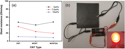
Table 2. According to CNT content sheet resistance value.
EMI shielding effectiveness (SE) is measured by testing how much incident light is blocked. The mechanism of EMI SE involves the reflection and absorption of electromagnetic (EM) waves. EM waves are attenuated in EMI shields through loss of electric and magnetic dipoles.[Citation25,Citation26] EMI SE obtained via parameter SEtotal (SET), SEreflection (SER) and SEabsorption (SEA). EMI shielding efficiency (SE) is obtained as the sum of SE of reflection and absorption.
T and R represent reflection and transmission, respectively, and are obtained by 2 and 3.
If the EMI SE is 10 dB, it represents that 90% of electromagnetic waves are shielded, 15 dB corresponds to 95%, and 20 dB to 99%.[Citation27–29] . shows the EMI SE according to the frequency, and . shows the average EMI SE value of the 8–12 GHz frequency band (X-band) of the composite films. In previous studies, when composites of CNTs (or inorganic substances) and polymers had a conductive filler content of 10 wt%, the EMI values were 15 dB and 12 dB for CF/PA6 and PC/ABS, respectively[Citation11]; even a conductive filler content of 20 wt% did not result in a shielding effect exceeding 17 dB.[Citation12] In this study, the EMI SE value increased with increasing CNT content in the composites. The EMI SE of CNT-based composites showed correlation between electromagnetic shielding and the contents of CNT as shown in . The difference between (c) and (d) in is due to the dispersibility and surface resistance. This is because FMN was well adsorbed to CNTs during annealing, and dispersion was better at uniform intervals inside the nylon matrix, which had good conductivity. This is because the surface resistance of MCNT(H) is smaller than that of MCNT. At 10 wt% of MCNT(H) in the composite, the average value of the X-band was 29.4 dB, and the EMI SE increased with increasing frequency (). In addition, the highest SE value obtained by the 10 wt% of MCNT(H) was 36.1 dB, confirming that electromagnetic shielding effectiveness was sufficient even at high frequency. Even with the same material, the EMI is different depending on the content and resistance. CNT and MCNT(H) show similar degrees depending on the resistance value. On the other hand, MCNT was increased at 5 and 7.5 wt% compared to both samples, but was measured to be 17.9 dB at 10 wt%. Because the content of FMN is increased, it is not mixed with CNT, causing deterioration of physical properties and properties.
Figure 8. Electromagnetic interference shielding effect of CNTs composite films (a) electromagnetic shielding scheme, (b) EMI SE of CNT, (c) EMI SE of MCNT, and (d) EMI SE of MCNT(H) composite films.
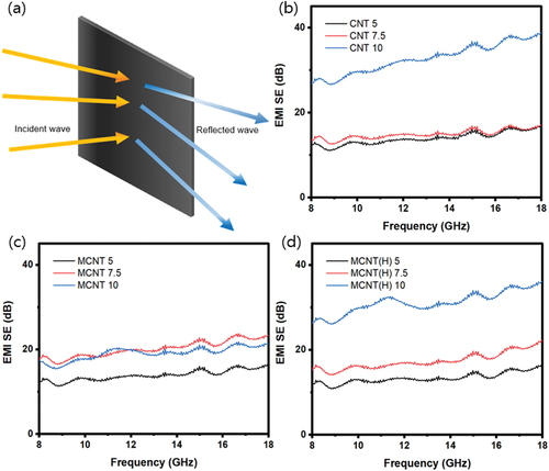
Table 3. Average dB value of in the X-band frequency range.
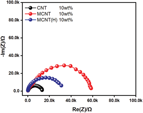
To confirm the electrochemical properties of the composites, the electrochemical impedance of the samples with the highest CNT content (10 wt%) was measured. . shows the Nyquist plot of each composite film (CNT 10, MCNT 10, and MCNT(H) 10) and is characterized by a circular arc in the frequency range of 1–100 MHz at a potential of 100 mV. The resistance is 11.2, 10.3, and 8.7 Ohms/sq, respectively; we could confirm that the diffusion of ions did not occur, as the resistance charge transfer is seen only in the semicircular region, which increases steeply in the high-frequency region and gradually decreases at the low frequency. Furthermore. there is no Warburg tail. Therefore, only the degree of resistance could be analyzed. The semicircular region represents the product of resistance and capacitor, and in the case of MCNT, it can be seen that FMN does not mix well, so the interfacial resistance is large. It can be seen that the MCNT(H) is larger than that of CNT, and it is mixed properly and the surface resistance is increased by wrapping the CNT surface with an isoalloxazine ring.
Figure 9. Electrochemical impedance spectroscopy of CNT 10 wt%, MCNT 10 wt% and MCNT(H) 10 wt%.
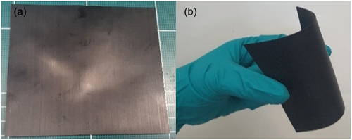
It is expected that the composites can be applied to various applications because of their light weight and flexibility, as shown in . In addition, owing to the low moisture absorption exhibited by nylon, the EMI shielding properties of the CNTs are expected to withstand sweat from the body without breaking down even when utilized in wearable electronic devices.
Figure 10. (a) MCNT(H)/Nylon12 composite filme and (b) flexibility of composite film.
4. Conclusions
CNT-based nylon 12 composites were manufactured to investigate their EMI SE properties. In order to disperse CNT within the composites, CNTs were modified using riboflavin 5’-monophosphate sodium. Composite films for each type of carbon nanotubes were fabricated with varying amounts of CNTs (5, 7.5, and 10 wt%). The mechanical and electrical properties were measured. The composite using 10 wt% of MCNT(H) showed well-dispersed despite increasing MCNT(H) content, and the tensile strength was improved compared to the CNT-nylon 12 composite. Furthermore, the resistance decreased to 8.7 Ohm/sq. In the case of EMI measurement, the incident wave blocking rate was the highest at 29.4 dB in the X-band for the MCNT(H) 10 wt%. Through this, when the CNTs were modified, it was confirmed that the annealed MCNTs (H) had superior mechanical properties and electrical properties than the MCNTs. Furthermore, MCNT(H) has improved mechanical properties and electrical properties than when it has the same content as CNT, which can reduce costs because almost half of FMN is used.
Acknowledgments
This study has been conducted with the support of the Korea Institute of Industrial Technology as “Development of fiber-based technology for reduction of hazardous substances in the air” (KITECH EO-22-0002)
Disclosure statement
No potential conflict of interest was reported by the author(s).
Additional information
Funding
Notes on contributors
Jae Hyuk Lee
Jae Hyuk Lee, science and engineering internship at KITECH, majoring in polymer science & engineering and biomolecular engineering.
Si-Hoon Jang
Si-Hoon Jang, researcher in KITECH, majoring in packaging and polymer chemistry.
Sang Yong Ju
Sang Yong Ju, Professor in Yonsei Univ., majoring in polymer chemistry and analytical chemistry
Eunkyoung Kim
Eunkyoung Kim, Professor in Yonsei Univ., majoring in chemical and biomolecular engineering.
No Hyung Park
No-Hyung Park, principal researcher in KITECH, majoring in polymer chemistry and processing.
References
- Tjong, S. C.; Liang, G. D.; Bao, S. P. Electrical Behavior of Polypropylene/Multiwalled Carbon Nanotube Nanocomposites with Low Percolation Threshold. Scr Mater. 2007, 57(6), 461–464. DOI: 10.1016/j.scriptamat.2007.05.035.
- Chae, S.-J.; Cho, B.-R.; Hong, B.-P.; Lee, B.S.; Byun, H.-S. Preparation of Sheet with CNT for EMI Shielding and Its EMI Shielding Property. Appl. Chem. Eng. 2010, 21, 430–434.
- Wang, Y.; Yang, C.; Xin, Z.; Luo, Y.; Wang, B.; Feng, X.; Mao, Z.; Sui, X. Poly(lactic Acid)/Carbon Nanotube Composites with Enhanced Electrical Conductivity via a Two-Step Dispersion Strategy, Compos. Commun. 2022, 30, 101087. DOI: 10.1016/j.coco.2022.101087.
- Al-Saleh, M. H.; Sundararaj, U. Electromagnetic Interference Shielding Mechanisms of CNT/Polymer Composites. Carbon. 2009, 47(7), 1738–1746. DOI: 10.1016/j.carbon.2009.02.030.
- Anand, S.; Muniyappan, S.; Racik, K. M.; Manikandan, A.; Mani, D.; Nandhini, S.; Karuppasamy, P.; Pandian, M. S.; Ramasamy, P.; Chandar, N. K., et al. Fabrication of Binary to Quaternary PVDF Based Flexible Composite Films and Ultrathin Sandwich Structured Quaternary PVDF/cb/g-C3N4/BaFe11. 5Al0. 5O19 Composite Films for Efficient EMI Shielding Performance. Synth. Met. 2022, 291, 117199. DOI: 10.1016/j.synthmet.2022.117199.
- Moon, D. J. A Study on Conductive Composites Manufacturing and Its Electromagnetic Shield Effectiveness. KSAE. A0297. 2016, 702–704.
- Kazmi, S. J.; Nadeem, M.; Warsi, M. A.; Manzoor, S.; Shabbir, B.; Hussain, S. PVDF/CFO-Anchored CNTs Ternary Composite System with Enhanced EMI Shielding and EMW Absorption Properties. J. Alloys Compound. 2022, 903, 163938. DOI: 10.1016/j.jallcom.2022.163938.
- Cao, S.; Tao, Y.; Li, H.; Ren, M.; Sun, J. Multiscale Hybrid CNT and CF Reinforced PEEK Composites with Enhanced EMI Properties. Nanocomposites. 2022, 8(1), 184–193. DOI: 10.1080/20550324.2022.2100683.
- Yan, D.; Zhang, H.-B.; Jia, Y.; Hu, J.; Qi, X.-Y.; Zhang, Z.; Yu, Z.-Z. Improved Electrical Conductivity of Polyamide 12/Graphene Nanocomposites with Maleated Polyethylene-Octene Rubber Prepared by Melt Compounding. ACS Appl. Mater. Interfaces. 2012, 4(9), 4740–4745. DOI: 10.1021/am301119b.
- Yan, D.; Li, X.; Ma, H.-L.; Tang, X.-Z.; Zhang, Z.; Yu, Z.-Z. Effect of Compounding Sequence on Localization of Carbon Nanotubes and Electrical Properties of Ternary Nanocomposites. Compos. Part A Appl. Sci. Manuf. 2013, 49, 35–41. DOI: 10.1016/j.compositesa.2013.02.002.
- Li, X.-H.; He, Y.; Li, X.; An, F.; Yang, D.; Yu, Z.-Z. Simultaneous Enhancements in Toughness and Electrical Conductivity of Polypropylene/Carbon Nanotube Nanocomposites by Incorporation of Electrically Inert Calcium Carbonate Nanoparticles. Ind. Eng. Chem. Res. 2017, 56(10), 2783–2788. DOI: 10.1021/acs.iecr.7b00446.
- Liu, Z.; Bai, G.; Huang, Y.; Ma, Y.; Du, F.; Li, F.; Guo, T.; Chen, Y. Reflection and Absorption Contributions to the Electromagnetic Interference Shielding of Single-Walled Carbon Nanotube/Polyurethane Composites. Carbon. 2007, 45(4), 821–827. DOI: 10.1016/j.carbon.2006.11.020.
- Huang, Y.; Li, N.; Ma, Y.; Du, F.; Li, F.; He, X.; Lin, X.; Gao, H.; Chen, Y. The Influence of Single-Walled Carbon Nanotube Structure on the Electromagnetic Interference Shielding Efficiency of Its Epoxy Composites. Carbon. 2007, 45(8), 1614–1621. DOI: 10.1016/j.carbon.2007.04.016.
- Lapinsky, S. E.; Easty, A. C. Electromagnetic Interference in Critical Care. J. Crit. Care. 2006, 21(3), 267–270. DOI: 10.1016/j.jcrc.2006.03.010.
- Johansen, C. Electromagnetic Fields and Health Effects—Epidemiologic Studies of Cancer, Diseases of the Central Nervous System and Arrhythmia-Related Heart Disease, Scand. J. Work Environ. Health. 2004, 30(1), 1–30.
- Beitollahi, H.; Movahedifar, F.; Tajik, S.; Jahani, S. A Review on the Effects of Introducing CNTs in the Modification Process of Electrochemical Sensors. Electroanalysis. 2019, 31(7), 1195–1203. DOI: 10.1002/elan.201800370.
- Biju, V. Chemical Modifications and Bioconjugate Reactions of Nanomaterials for Sensing, Imaging, Drug Delivery and Therapy. Chem. Soc. Rev. 2014, 43(3), 744–764. DOI: 10.1039/c3cs60273g.
- Firkowska, I.; Boden, A.; Vogt, A.-M.; Reich, S. Effect of Carbon Nanotube Surface Modification on Thermal Properties of Copper–CNT Composites. J. Mater. Chem. 2011, 21(43), 17541–17546. DOI: 10.1039/c1jm12671g.
- Mallakpour, S.; Soltanian, S. Chemical Surface Coating of MWCNTs with Riboflavin and Its Application for the Production of Poly(ester-imide)/MWCNTs Composites Containing 4,4′-Thiobis(2-Tert-Butyl-5-Methylphenol) Linkages: Thermal and Morphological Properties. J. Appl. Polym. Sci. 2016, 133(4), n/a–n/a. DOI: 10.1002/app.42908.
- Griehl, W.; Ruestem, D. Nylon-12-Preparation, Properties, and Applications, Ind. Eng. Chem. 1970, 62(3), 16–22. DOI: 10.1021/ie50723a005.
- Park, M.; Yoon, S.; Park, J.; Park, N.-H.; Ju, S.-Y. Flavin Mononucleotide-Mediated Formation of Highly Electrically Conductive Hierarchical Monoclinic Multiwalled Carbon Nanotube-Polyamide 6 Nanocomposites. ACS Nano. 2020, 14(8), 10655–10665. DOI: https://doi.org/10.1021/acsnano.0c05170.
- Choi, I.-S.; Park, M.; Koo, E.; Ju, S.-Y. Dispersions of Carbon Nanotubes by Helical Flavin Surfactants: Solvent Induced Stability and Chirality Enrichment, and Solvatochromism. Carbon. 2021, 184, 346–356. DOI: 10.1016/j.carbon.2021.08.054.
- Ju, S.-Y.; Abanulo, D. C.; Badalucco, C. A.; Gascón, J. A.; Papadimitrakopoulos, F. Handedness Enantioselection of Carbon Nanotubes Using Helical Assemblies of Flavin Mononucleotide. J. Am. Chem. Soc. 2012, 134(32), 13196–13199. DOI: 10.1021/ja305250g.
- Lee, J. K., Kim, S.C.; Kim, H.J.; Lee, C.G.; Ju, C.H.; Lee, L.C. A Study on the Zeta Potential Measurement and the Stability Analysis of Nanofluids Using a Particle Image Processing System. Institute for Liquid Atomization and Spray Systems-Korea (ILASS). 2003, 8, 16–22.
- Mei, H.; Zhao, X.; Gui, X.; Lu, D.; Han, D.; Xiao, S.; Cheng, L. SiC Encapsulated Fe@ CNT Ultra-High Absorptive Shielding Material for High Temperature Resistant EMI Shielding. Ceram. Int. 2019, 45(14), 17144–17151. DOI: 10.1016/j.ceramint.2019.05.268.
- Das, P.; Deoghare, A. B.; Ranjan Maity, S. Synergistically Improved Thermal Stability and Electromagnetic Interference Shielding Effectiveness (EMI SE) of in-Situ Synthesized Polyaniline/Sulphur Doped Reduced Graphene Oxide (PANI/S-RGO) Nanocomposites. Ceram. Int. 2022, 48(8), 11031–11042. DOI: 10.1016/j.ceramint.2021.12.323.
- Zhang, C.-S.; Ni, Q.-Q.; Fu, S.-Y.; Kurashiki, K. Electromagnetic Interference Shielding Effect of Nanocomposites with Carbon Nanotube and Shape Memory Polymer, Compos. Sci. Technol. 2007, 67(14), 2973–2980. DOI: 10.1016/j.compscitech.2007.05.011.
- Wu, N.; Hu, Q.; Wei, R.; Mai, X.; Naik, N.; Pan, D.; Guo, Z.; Shi, Z. Review on the Electromagnetic Interference Shielding Properties of Carbon Based Materials and Their Novel Composites: Recent Progress, Challenges and Prospects. Carbon. 2021, 176, 88–105. DOI: 10.1016/j.carbon.2021.01.124.
- Dou, R.; Shao, Y.; Li, S.; Yin, B.; Yang, M. Structuring Tri-Continuous Structure Multiphase Composites with Ultralow Conductive Percolation Threshold and Excellent Electromagnetic Shielding Effectiveness Using Simple Melt Mixing. Polymer. 2016, 83, 34–39. DOI: 10.1016/j.polymer.2015.12.005.