
 ?Mathematical formulae have been encoded as MathML and are displayed in this HTML version using MathJax in order to improve their display. Uncheck the box to turn MathJax off. This feature requires Javascript. Click on a formula to zoom.
ABSTRACT
Quenching is a widely used process in heat treatment enterprises. Clean and cheap water quenching instead of high pollution and high cost of oil quenching or polymer aqueous solution quenching will become a trend in these enterprises. However, since the cracking problem of alloy steel parts induced by water quenching with high cooling rate has not been solved, the oil and polymer aqueous solution with low cooling rate are still widely used in various countries in the world. Water–air alternative timed quenching’ process and differential time grading quenching process proposed by us have been successfully applied to treat various large-size alloy steel parts in China. In this review paper, we will introduce the face issues in the design of these two kinds of processes based on finite element simulation (FES): (1) Main factor affecting accurate prediction of quenching stress; (2) The method to determine the optimizing process. Two engineering examples are selected to clarify how to solve the cracking issues of alloy steel part by FES.
Introduction
Quenching is one of the most important heat-treatment processes for improving the mechanical properties of alloy steels [Citation1]. It is a process of rapid cooling of high-temperature austenite to obtain high-strength martensite or bainite structure. Clean and cheap water quenching instead of high pollution and high cost of oil quenching or polymer aqueous solution quenching will become a trend in the heat treatment industry. However, since the cracking problem of alloy steel parts induced by water quenching with high cooling rate has not been solved, the oil and polymer aqueous solution with low cooling rate are still widely used in various countries in the world. Water–air alternative timed quenching (ATQ) process proposed by us 15 years ago has been successfully applied to treat various large-size alloy steel parts in China [Citation2], however, the design of ATQ process mainly relies on experiments, rather than finite element simulation (FES) since we have not established the simulation of stress field based on the simulations of temperature field and microstructure field. The FES of temperature field and microstructure field cannot solve the cracking induced by water quenching. If the prediction of stress field cannot be made by FES, the cracking problem induced by water quenching has to need a large number of experiments to solve. However, experimental measurements have three main limitations: (1) for a large and complex component, the measurement of the internal stress as a function of depth is not only difficult but also time-consuming; (2) in most cases, cracking of a quenched component is caused by transient stress during quenching, whereas the experiment can only measure the final internal stress (residual stress), rather than the transient stress; and (3) the origin of complex quenching stresses cannot fully be understood if there is no assist of computer simulation of the stress analysis. As Totten and Albano pointed out [Citation3] that ‘two important topics that are an integral part of the current status and future directions of quenching technology development are the material bases for residual stress and distortion control and modelling and the role of modelling and simulation in materials and process design’. For these reasons, the FES of quenching was rapidly developed to predict the temperature, phase, and stress evolution to optimize the quenching process [Citation4–7]. In the development of computer simulations, transformation plasticity (TP) is one of the difficult issues that need to be addressed to obtain a precise prediction of the residual stress. TP is an irreversible strain observed when metallurgical transformation occurs under a small external stress lower than the yield stress of the weaker phase [Citation8–10]. The effect of TP on the simulated residual stress causes some divergences [Citation11–14]. Taleb [Citation8] measured the variation of TP with the volume fraction of bainite, which was termed ‘TP’ kinetics, and compared it with the prediction based on functions describing the TP kinetics proposed by Abrassart, Desalos, and Leblond. The result indicates that their functions lead to almost the same kinetics, which largely underestimates the experimental result. Recently, we proposed an exponent-modified (Ex-Modified) normalized function describing the TP strain [Citation14], which was used to fit the experimental result from Taleb et al. [Citation8] showing that the Ex-Modified normalized function better describes the TP kinetics than Abrassart’s, Desalos's and Leblond’s functions, in turn, the FES for the residual stress distributions in quenched AISI 4140 cylinders with two diameter sizes better agrees with XRD measurements [Citation15].
In this review paper, we will introduce how to improve the accuracy of quenching stress prediction by an exponent-modified (Ex-Modified) normalized function describing the TP strain, and how to solve the cracking during water quenching mainly by FES via two engineering examples selected.
Proposal of ex-modified function
Taleb et al. [Citation8] noted that Abrassar’s, Desalos’s, and Leblond’s functions largely underestimate the experimental results. Therefore, we analyzed the curve feature of the normalized function, , measured by Taleb et al. [Citation8] At the initial stage of transformation, the normalized function rapidly increases, and at the ending stage of transformation, it slowly increases. According to the analysis mentioned above, we proposed an Ex-Modified normalized function linking with the TP strain:
(1)
(1) where A is a parameter used to adjust the normalization. Equation (2) was used to fit the experimental curve of Taleb et al. [Citation8], and the parameters in Equation (2) were determined to be A = 1.105, B = −0.0994, and n = −0.91, as shown in and [Citation16] shows the comparison between the experimental result from Taleb et al. [Citation8] and the calculated results based on Desalos’s, Abrassart’s, Leblond’s and Ex-Modified functions, and the result indicates that the Ex-Modified normalized function better describes the TP kinetics than Abrassart’s, Desalos’s and Leblond’s functions.
Figure 1. Comparison between experimental result from Taleb et al. and the calculated results based on Desalos’s, Abrassart’s, Leblond’s and ex-modified functions.
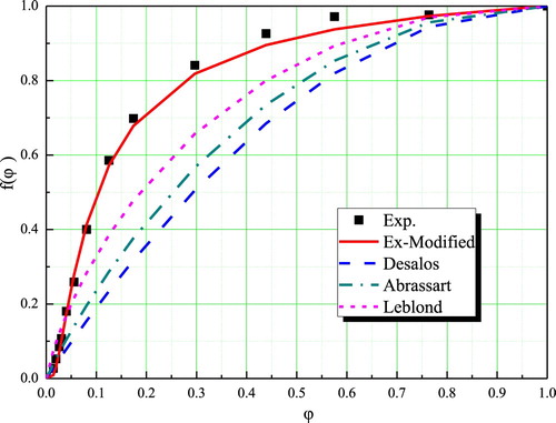
Table 1. Various expressions of  functions.
Stress analysis
During the process of quenching, the total strain increment was divided into five parts:(2)
(2) where
,
,
,
and
are the strain increments for the elastic, plastic, thermal, phase transformation, and TP components, respectively. Assuming that the materials are isotropic, the thermal strain and transformation strain increment are also isotropic, and can be calculated by the following equations, respectively:
(3)
(3) where εk is the relative strain of the k phase and was calculated based on experimental thermal expansion curves; T is the absolute temperature.
When phase transformations occur under stress, an anomalous plastic strain, known as TP, will occur even though the equivalent stress of the external stresses is below the yield strength of austenite. The increment of the TP strain is expressed as [Citation17](4)
(4) where K(
) is the TP coefficient, sij denotes the deviatoric stress tensor;
is the derivative function of the
normalized function in Equation (1); and the various expressions of
proposed by Abrassart, Desalos, Leblond and the authors are shown in ;
is the increment of volume fraction of various phases.
If the thermal stress is calculated separately, Equation (3) can be rewritten as follows:(5)
(5)
If the phase transformation stress is calculated separately, Equation (3) can be rewritten as follows:(6)
(6)
Residual stress induced by quenching is the overlapping of thermal stress and phase transformation stress.
Effect of the normalized functions on the internal stress
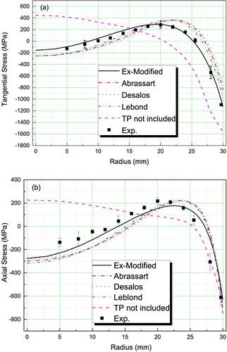
A comparison between the measured and calculated internal stresses in the 40CrNiMo steel based on four normalized functions (Ex-Modified, Abrassart, Desalos, and Leblond) was performed, as shown in [Citation1]. The FES of the distribution of the internal stresses based on the Ex-Modified normalized function, including the axial and tangential stresses, is more consistent with that measured by XRD than the FES based on the normalized functions proposed by Abrassart, Desalos, and Leblond. This is because the Ex-Modified normalized function better describes the TP. The FES coupled with an improved TP function reconfirms the importance of accurate models for better prediction of residual stress when dealing with TP kinetics. It is worthy to point out that if the effect of TP on stress in simulation don't consider, demonstrates that the simulation prediction is tensile stress in the center of the cylinder, while the measured value is compressive stress, which leads to the prediction and measured inversion.
Figure 2. Measured and calculated residual stress distributions based on various TP equations of 60 mm-diameter 40CrNiMo after water quenching: (a) tangential stress and (b) axial stress.
Two engineering examples
The cracking of alloy steel parts during quenching is caused by transient tensile stress. The transient stress caused by quenching is the overlapping of thermal stress and phase transformation (or microstructure) stress. The thermal stress and microstructure stress in quenching process cannot be measured by experiment but can be calculated separately by FES. As a result, thermal stress or microstructure stress can be identified as the leading cause of cracking. The related theory is provided for the improvement of process.
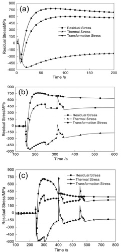
A 42CrMo drive shaft avoiding cracking by adjusting the process parameters to reduce the maximum tensile stress is taken as an example [Citation18]. shows the FES mesh of drive shaft. By changing the process parameters, such as pre-cooling time, water quenching time, air cooling time and the number of water–air alternations, the effects of these parameters on thermal stress, phase transformation stress and synthetic stress (quenching stress) were studied, respectively, and two processes ATQ1 and ATQ2 were designed. As can be seen from , direct water quenching (DQ) leads to almost constant maximum radial tensile stress, which is easy to cause cracking by residual tensile stress at easy cracking edges and corners. For ATQ process, however, every time of the water–air alternations (ATQ1 and ATQ2) cooling makes the stress decrease, the maximum radial tensile stress is pulsed (caused by thermal stress), ATQ2 is more effective than ATQ1 to avoid quenching cracking tendency, which is consistent with the actual production situation. At first, ATQ1 process was adopted to treat 100 pieces, among which four pieces produced edge and corner cracking, then, improved ATQ2 process was adopted, and no quenching cracking occurred.
Figure 3. FES mesh of drive shaft.
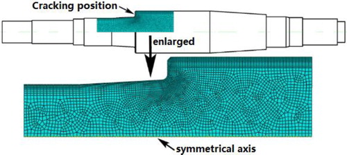
Figure 4. Finite element simulation of radial quenching stress of the driving shaft in different quenching ways: DQ (a), ATQ1 (b), and ATQ2 (c).
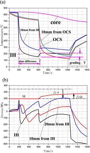
The process design of wind-electric spindle with inner hole by water quenching is taken another example. In principle, the performance of wind-electric spindle with inner hole before quenching is far higher than that of the wind-electric spindle with inner hole after quenching, but due to the problem of easily cracking during quenching, only a few enterprises at home and abroad try using polymer aqueous medium by adjusting the concentration of medium solve the problem of inner hole cracking, but no enterprises adopt the way of water quenching to solve the problem of inner hole cracking. For the sake, some domestic enterprise has made a variety of water-quenching processes, but none of them (including ATQ process) could avoid cracks in the inner hole. We selected one of failure processes exhibiting the smallest crack induced by water quenching from this enterprise to carry out finite element simulation on temperature and stress distribution, as shown in , and on this basis, we found the cracking origin from many influence factors, and thus proposed differential time grading quenching (DTGQ) process, and this new process was successfully applied in the six models of hundred products, and the toughness of the products is 2 times higher than the index requirement. The mechanism of DTGQ process to avoid cracking: (1) Differential time cooling: water cooling in advance of the inner hole ((a)) was performed, and thus in cooling time there is Δt between the inner hole and the outer circle surface of the wind-electric spindle, achieving the goals of both reducing the peak tensile stress in the inner hole and pushing the peak tensile stress inward; (2) Grading cooling: after the first stage of strong cooling, martensitic transformation takes place in the surface, then during simultaneous cooling of inner hole and outer circle surface the water cooling intensity of the inner hole is weaken (reduce the flow rate of the water in the inner hole) resulting in the ΔT increment of inner hole surface temperature, meanwhile, at inner hole surface martensite gets self-tempering, and thus fracture resistance (Sk)value increases by ΔSk ((b)). Under the such two actions mentioned above, the stress reduction and the Sk value increase of the inner hole effectively avoid the crack formation at the inner hole surface.
Figure 5. Variation of temperature (a) and stress (b) with time calculated by FES for failure process inner hole (IH), outer circle surface (OCS).
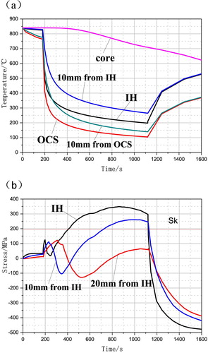
Figure 6. Variation of temperature (a) and stress (b) with time calculated by FES for DTGQ process inner hole (IH), outer circle surface (OCS).
Two examples mentioned above clarifies the method of process design based on FES, that is, by changing the process parameters, the minimum tensile stress can be expected to obtain in the easy cracking site, and self-tempering martensite enhances fracture resistance (Sk).
Summary
The substitution of water quenching for traditional oil quenching in ATQ and DTGQ processes is of great significance in environmental protection. However, the cracking of alloy steel parts is easily caused by water quenching and has not been solved for a long time. Therefore, oil quenching and polymer aqueous solution are still widely used in heat treatment enterprises all over the world. We use FES to design the water quenching process and solve the cracking problem well. Accurate prediction of transient stress is the key in FEM of quenching process. The precision of transient stress prediction is determined by the accurate description of TP. In the design of optimum process, the tensile stress should be minimized at the cracking site and martensite should experience self-tempering to enhance fracture resistance, which can effectively avoid the cracking during water quenching.
Acknowledgements
The work is financially supported by the National Key R&D Program of China (No. 2017YFB0304500) and the National Natural Science Foundation of China (No. 51771114).
Disclosure statement
No potential conflict of interest was reported by the author(s).
References
- Liu Y, Qin S, Zhang J, et al. Influence of transformation plasticity on the distribution of internal stress in three water-quenched cylinders. Metall Mater Trans A. 2017;48:4943–4956. doi: 10.1007/s11661-017-4230-7
- Zuo XW, Chen NL, Gao F, et al. Development of multi-cycle quenching–partitioning–tempering process and its applications in engineering. Inter Heat Treat Surf Eng. 2014;8:15–23. doi: 10.1179/1749514813Z.00000000078
- Totten GE, Albano LLM. IFHTSE global 21: heat treatment and surface engineering in the twenty-first century. Int Heat Treat Surf Eng. 2012;6:4–14. doi: 10.1179/1749514811Z.0000000001
- Inoue T, Arimoto K. Development and implementation of CAE system ‘hearts’ for heat treatment simulation based on metallo-thermo-mechanics. J Mater Eng Perform. 1997;6:51–60. doi: 10.1007/s11665-997-0032-1
- Denis S, Sjostrom S, Simon A. Coupled temperature, stress, phase transformation calculation. Metall Trans A. 1987;18A:1203–1212. doi: 10.1007/BF02647190
- Bok HH, Choi JW, Suh DW, et al. Stress development and shape change during press-hardening process using phase-transformation-based finite element analysis. Int J Plast. 2015;73:142–170. doi: 10.1016/j.ijplas.2014.11.004
- Lee MG, Kim SJ, Han HN, et al. Implicit finite element formulations for multi-phase transformation in high carbon steel. Int J Plast. 2009;25:1726–1758. doi: 10.1016/j.ijplas.2008.11.010
- Taleb L, Cavallo N, Waeckel F. Experimental analysis of transformation plasticity. Int J Plast. 2001;17:1–20. doi: 10.1016/S0749-6419(99)00090-X
- Greenwood GW, Johnson RH. The deformation of metals under small stresses during phase transformations. Proc R Soc Lond A. 1965;283:403–422. doi: 10.1098/rspa.1965.0029
- Han HN, Lee JK. A constitutive model for transformation superplasticity under external stress during phase transformation of steels. ISIJ Int. 2002;42:200–205. doi: 10.2355/isijinternational.42.200
- Inoue T, Wakamatsu H. Unified theory of transformation plasticity and the effect on quenching simulation[J]. Strojarstvo. 2011;53(1):11–18.
- Denis S, Gautier E, Simon A, et al. Stress–phase-transformation interactions – basic principles, modelling, and calculation of internal stresses. Mater Sci Technol 1985;1:805–814. doi: 10.1179/mst.1985.1.10.805
- Wang KF, Chandrasekar S, Yang HTY. Experimental and computational study of the quenching of carbon steel. J Manuf Sci Eng. 1997;119:257–265. doi: 10.1115/1.2831102
- Nagasaka Y, Brimacombe JK, Hawbolt EB, et al. Mathematical model of phase transformations and elastoplastic stress in the water spray quenching of steel bars. Metall Trans A. 1993;24A:795–808. doi: 10.1007/BF02656501
- Liu Y, Qin S, Hao Q, et al. Finite element simulation and experimental verification of internal stress of quenched AISI 4140 cylinders. Metall Mater Trans A. 2017;48A:1402–1413. doi: 10.1007/s11661-016-3916-6
- Liu Y. Measurements and finite element simulation of quenching stress distribution in medium carbon steels [dissertation of the doctoral degree]. Shanghai Jiao Tong University; 2017.
- Fischer FD, Sun QP, Tanaka K. Transformation-induced plasticity (TRIP). Appl Mech Rev. 1996;49:317–364. doi: 10.1115/1.3101930
- Rong Y, Zuo X, Chen N. Clean water-air alternative timed quenching (ATQ) technology: principle and applications[J]. Jinshu Rechuli/Heat Treat Met. 2018;43(4):1–9.