
 ?Mathematical formulae have been encoded as MathML and are displayed in this HTML version using MathJax in order to improve their display. Uncheck the box to turn MathJax off. This feature requires Javascript. Click on a formula to zoom.
ABSTRACT
Nanoeutectic oxide layers have been obtained by laser surface nanocrystallization on oxide ceramics with eutectic composition. The eutectic layer can effectively improve the surface performance of oxide materials. This paper provides a comprehensive review of this promising technique. It includes the numerical simulation of temperature field in the melt pool associated with laser surface melting, formation mechanisms and growth kinetics of the coupled nanoeutectic structure, and the influence of processing parameters on structure and properties of eutectic oxide layer. In combination with other preparation techniques, such as directional solidification and additive manufacturing methods, the formation mechanism and prevention of bubbles and cracks are clarified. The relationship between microstructure and performance with gradient feature is also indicated. This review attempts to inspire imaginations and insights into material design and process optimization for laser surface nanocrystallization of oxide ceramics with eutectic composition.
Introduction
Due to clean and strong interface and fine three-dimensional entanglement microstructure, eutectic ceramics grown from the oxide melt can effectively overcome the softening or sliding of phase-/grain-boundaries operating in a high-temperature environment. Therefore, they have higher strength and toughness than traditional as-sintered ceramics, especially near the melting point. In addition, some special properties in optics, electricity and magnetism of oxide eutectic ceramics also came to light recently [Citation1]. Since the Al2O3-based eutectic systems have good creep resistance and high-temperature strength retention, the research on them is most extensive and in-depth, mainly including Al2O3–ZrO2(Y2O3), Al2O3–RE3Al5O12(REAG) (RE = Y, Er), Al2O3–REAlO3 (RE = Sm, Gd) and other binary eutectic systems, and Al2O3–RE3Al5O12 (RE = Y, Er)–ZrO2(Y2O3), Al2O3–REAlO3 (RE = Sm, Gd)–ZrO2(Y2O3) and other ternary eutectic systems.
The directional solidification methods for preparing oxide eutectic ceramics have been developed since the last century, such as the Bridgman method [Citation2–4], micro-pulling down method (μ-PD) [Citation5–8], edge-defined film-growth method [Citation9,Citation10], laser floating zone melting (LFZ) [Citation11–13], optical floating zone method (OFZ) [Citation14,Citation15], modified electron beam floating zone method (EBFZM) [Citation16] and laser surface melting [Citation17–21]. Mainstream efforts are devoted to the mechanism of the coupled eutectic growth and the optimization of processing parameters. The mechanical properties of eutectic ceramics can be improved by controlling the temperature gradient and solidification rate to achieve a uniform and fine microstructure. Generally, temperature gradient and growth rate, which the early Bridgman method can achieve, are very low, less than 100 K·cm−1 and 100 mm·h−1, respectively. As a result, the eutectic spacing is large, usually above 10 μm [Citation2,Citation3]. The maximum temperature gradient of the μ-PD method can reach 5 × 10³ K·cm−1, and the growth rate can reach 0.05–20 mm min−1 [Citation5]. However, limited by the volume of a high-temperature directional-solidification vacuum induction melt furnace, it is only suitable for the preparation of high-performance submicron-phase ceramic fibers with relatively poor efficiency. In floating zone melting method, a small amount of precursor is melted, and surface tension maintains the stability of the melt between the solidified crystal and the precursor. LFZ seems to attract more attention due to its wide range of parameter adjustment.
However, a large temperature gradient will generate a large thermal stress, which is the main reason why eutectic ceramic components with a large size cannot be fabricated. The internal stress in eutectic ceramics is mainly composed of two parts, one is the thermal mismatch stress caused by different coefficients of thermal expansion of each phase, and the other is the thermal stress caused by large temperature gradient at the solid/liquid interface. The latter may vary with the preparation method. In LFZ, the excessive axial gradient at the interface during the growth process is the main reason for cracks [Citation22,Citation23], while in selective laser melting (SLM) the thermal shrinkage tendency of solidified powders is constrained by the cold substrate, which results in high quenching stress [Citation24].
Initially, laser surface melting applied to oxide ceramics was mainly used to eliminate surface defects and form a crack-free, dense, smooth and homogeneous surface solidified layer. Thus, it can repair the surface of refractory ceramics, optimize the surface wettability and improve the wear resistance [Citation25,Citation26]. Compared with other surface modification technologies, it mainly has the following advantages: (1) it has extremely high heating and cooling rates, which can realize the refinement of microstructure; (2) it can effectively avoid chemical pollution on the surface due to its non-contact heating mode; (3) the heating time is very short and the heat affected zone is small so that the workpiece has less deformation and is easy to achieve selective surface modification; (4) it can form a metallurgical bonding between the solidified layer and substrate; (5) it is suitable for large-area and complex surfaces and is promising to develop industrial automatic production. Sintered multiphase composite ceramics can combine the advantages of each component. Especially when ZrO2 is contained, as-sintered ceramics have high fracture toughness due to the phase transformation toughening effect [Citation27,Citation28]. Larrea et al. [Citation17] used a rectangular laser beam size of 20 × 0.5 mm2 to fabricate a eutectic layer on the surface of as-sintered Al2O3–ZrO2 ceramic for the first time. (a) shows the schematic diagram of a large-area laser surface melting equipment [Citation29]. The Al2O3–ZrO2 eutectic layer, prepared by Guruskis et al. [Citation29], consists mainly of a large number of elongated cells with orientation characteristics, as shown in the cross-section ((b)). It is quite dense without any obvious defects such as cracks, bubbles and delamination, and the surface after laser treatment is still smooth, as shown in (c–d). The high-performance eutectic layer is formed from the melt by the eutectic reaction on the ceramic substrate. It can produce a larger surface eutectic ceramic layer grown with a high-temperature gradient and growth rate at a lower cost, which makes this method attractive and promising [Citation18]. Since this method is born out of directional solidification and laser surface modification, understanding the formation mechanism of eutectic structure and the interaction between laser beam and oxide ceramics is the prerequisite for process optimization. There are also similarities with additive manufacturing techniques based on laser for rapid solidification of the molten pool. Hence, in combination with corresponding eutectic ceramic preparation methods with laser surface modification, the relationship between laser processing parameters, microstructure and properties of the nanoeutectic oxide layer is discussed and summarized in this paper.
Figure 1. Nanoeutectic layer fabrication via laser rapid solidification process on the surface of Al2O3–ZrO2 ceramic [Citation29]: (a) laser quasi-continuous line and experimental setup, (b) the colonies formed by laser surface melting, (c) surface morphology, (d) cross-section of the formed layer. Reproduced with permission from Ref. [Citation29], © Elsevier Ltd. 2010.
![Figure 1. Nanoeutectic layer fabrication via laser rapid solidification process on the surface of Al2O3–ZrO2 ceramic [Citation29]: (a) laser quasi-continuous line and experimental setup, (b) the colonies formed by laser surface melting, (c) surface morphology, (d) cross-section of the formed layer. Reproduced with permission from Ref. [Citation29], © Elsevier Ltd. 2010.](/cms/asset/0d08ae2e-5950-486a-8aec-07fd4c76bf42/thts_a_2026046_f0001_ob.jpg)
Numerical simulation of temperature field
The melt growth is controlled by the temperature field in laser melt pool. Not only that, a considerable number of phenomena such as instability, segregation, internal stress and cracking are also closely related to the temperature distribution [Citation30]. However, it is very difficult to measure the temperature distribution in the melt pool especially through experiments. Therefore, using numerical simulation to predict the temperature field in the laser surface melting process is considered to be a practical measure. In additive manufacturing such as SLM and laser directed energy deposition (LDED), numerical simulation has been widely used [Citation31–33].
The situation in the real melt pool is very complicated, including the heat transfer such as conduction, radiation and convection, the mass transfer such as internal material migration and surface melt/vaporization, phase transition, fluid flow and surface tension changes, etc. To obtain the accurate thermal field requires a deeper perception of these factors. The heat transfer process starts from the energy that material received from the laser. Early research on ceramics mostly used the same surface heating source model as metals. Li et al. [Citation34] pointed out that most ceramics have poor irradiation absorptivity. The reflectivity of long wavelength infrared laser is much lower than that of metal, and the absorption path length of CO2 laser is much higher than that of metal, which has been experimentally verified by Lawrence et al. [Citation35]. Consequently, the laser-induced thermal field of ceramics should be more suitable for modeling with volumetric heating source described by the Beer–Lambert’s Law. The x–y plane and the origin of the Cartesian coordinate system coincide with the workpiece surface and the center of the laser beam respectively. Then, the heat source distribution function q(x, y, z) can be expressed as [Citation34]:
where R is the reflectivity of the material, γ is the laser absorption length, z is the penetration depth, I(x, y) is the x–y plane laser intensity distribution, which is determined by the laser beam modes. Thus, the quasi-steady heat conduction governing equation in the thermodynamically isotropic material is given by [Citation34]:
with the boundary conditions:
where T is the absolute temperature, T0 is the environmental temperature, V0 is the scanning rate, α is the thermal diffusion coefficient, k, ρ and Cp are the thermal conductivity, density and specific heat capacity of the material respectively. Furthermore, a three-dimensional numerical model of the convection–diffusion phase transition process based on a fixed-grid source-based method and a three-dimensional finite element model to study the evolution of thermal stress were established in laser melting of ceramics, focusing on the influences of the latent heat of melting and fluid flow [Citation36,Citation37]. Bityukov et al. [Citation38] considered the special thermophysical properties of translucent alumina ceramics with temperature and optical properties in the numerical model, which may affect the laser absorption and radiation heat transfer. The vaporization of the surface melt was taken into account as well when solving the problem of phase transition. The temperature of the solid phase is similar under different radiation fluxes because of very high absorption coefficient of the melt in the wavelength range of highest energetic importance to radiation transfer. Moreover, the vaporization of the melt surface under high radiant flux affects the formation of the temperature field before reaching the quasi-steady state. Hao et al. [Citation39] established a transient finite element model for laser surface treatment of MgO–PSZ ceramic with a stepwise moving laser source. The simulation results of surface temperature, melt pool width and depth were in agreement with the measured values, while they considered the residuals attributable to the type of substrate and laser beam. Previous studies noticed the radiation-conduction phenomenon of refractory oxides [Citation40], and the thermal radiation characteristics of many common oxide ceramics have been summarized by Petrov [Citation41]. The discussion on the difference between the brightness temperature and the actual temperature during laser irradiation of refractory oxides was carried out by Bityukov et al. [Citation42]. The difference is positively correlated with the radiant flux density and inversely correlated with the melt thickness after the melt is stabilized, which is of great significance to the correction of the brightness temperature.
Recent numerical simulation mainly focused on the selective laser melting process. It is noteworthy that this method uses ceramic powders as the precursor. The laser is not only absorbed directly but also reflected multiple times when irradiating powders, which increases the depth and width of the laser energy deposition zone and irradiation absorptivity of ceramic powders. Meanwhile, the radial transfer of radiation energy will reduce the energy density at the center of the laser spot [Citation43,Citation44]. Thus, a more accurate heat source model should be applied. Since thermal conductivity of the powder is lower than that of the bulk, radiation may contribute more to heat transfer than conduction in the powder [Citation45]. Chen et al. [Citation46,Citation47] proposed a finite element model with the Level Set method, in which dynamic mesh adaptation was used to capture the continuous evolution from powders to droplets then aggregating. The Marangoni effect caused by the surface tension gradient related to the temperature distribution will affect the internal flow of the melt. It was introduced into the model to predict convection and heat flow closer to the real situation. In detail, the Marangoni surface force τ is expressed as [Citation47]:
where ∂σ/∂T is the surface tension gradient, ∇sT is the surface temperature gradient, and
is the unit vector normal to the interface. Moreover, the surface force can be transformed into the volume force by a Dirac function δST. In Ma’s model [Citation48], the Marangoni number including the vertical Marangoni number Mver and the horizontal Marangoni number Mhor was calculated, and the stability-instability transition of the melt surface at different processing parameters was investigated. The flow pattern can be predicted by Mver and Mhor, which are defined as [Citation49]:
where ΔTver is the vertical temperature difference of the liquid layer, gradxT is the horizontal temperature gradient along the free surface, d is the thickness of the liquid layer, and η is the dynamic viscosity. Near the liquid surface, with the increase of Mver or the decrease of Mhor, the transition ‘steady flow → longitudinal roll → Bénard–Marangoni drifting cell’ will occur [Citation49]. More phenomena can be predicted, such as the evolution of surface morphology during raster scan, with perfecting the models [Citation50]. Collectively, special thermophysical properties of refractory oxides hinder the accurate modeling and their effects on the radiation process need further research. In particular, the experimental data of properties near the melting point of refractory oxide ceramics are missing, which is an indispensable area for further work.
Microstructure and formation mechanism of the eutectic layer
Evolution of nanoeutectic microstructure
The schematic illustration of laser surface nanocrystallization is shown in [Citation21]. Firstly, the as-sintered ceramic was placed on a self-designed stationary preheating plate, and then it was processed by a linearly moving laser beam, which was driven by a six-axis ABB robot system. Meanwhile, the argon was continuously blown to protect the sample and laser lenses at a suitable flux. It is a rapid melting and solidification of ceramic melt pool during the advancing process on the surface essentially. presents the microstructure evolution of the solidified nanoeutectic layer from the substrate to the surface. The Al2O3–ZrO2 nanoeutectic layer prepared in this process is the oriented cellular eutectic epitaxially grown along the boundary of the substrate, which is mainly composed of oriented columnar eutectic and equiaxed eutectic cells. The growth of columnar eutectic cells in the bottom area of the melt pool mainly proceeds along the inverse heat transfer direction perpendicular to the pool boundary. The solidification behavior can be roughly divided into the following three processes: the oriented nucleation of the nanoeutectic on the substrate ((a)), the competition, preferred orientation growth and deflection of columnar eutectic cells in the middle area ((b)), and the nucleation and growth of equiaxed crystals near the surface ((c)). presents surface morphologies obtained from the center of nanostructured Al2O3–ZrO2 eutectic layer, in which well-established eutectic colonies are clearly visible, showing a radiated structure originating from the ZrO2-dendrite core [Citation21].
Figure 2. Schematic illustration of the laser surface melting setup and the solidification process for surface nanocrystallization of Al2O3–ZrO2 ceramic with eutectic composition [Citation21]: (a) the setup for laser surface melting, (b) the solidification process. Reproduced with permission from Ref. [Citation21], © Elsevier B.V. 2019.
![Figure 2. Schematic illustration of the laser surface melting setup and the solidification process for surface nanocrystallization of Al2O3–ZrO2 ceramic with eutectic composition [Citation21]: (a) the setup for laser surface melting, (b) the solidification process. Reproduced with permission from Ref. [Citation21], © Elsevier B.V. 2019.](/cms/asset/fc14176f-5b3e-4c87-9e74-426f18e01a2b/thts_a_2026046_f0002_oc.jpg)
Figure 3. Cross-section microstructural evolution of Al2O3–ZrO2 nanoeutectic layer: (a) the chilled substrate, the interface and internal surface microstructure of nanostructured eutectic layer, (b) columnar eutectic growth in the middle, (c) equiaxed eutectic solidification near the surface layer.
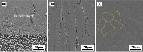
Figure 4. Surface morphology of Al2O3–ZrO2 nanoeutectic layer [Citation21]: (a) representative single dendritic ZrO2-cored eutectic colony generated by equiaxed solidification, (b) enlarged view of (a), presenting the irregular Chinese-script nanoeutectic, (c) branched structure of ZrO2 primary dendritic core, corresponding to the arrow in (a), (d) enlarged view of (c), showing the dendrite core structure. Reproduced with permission from Ref. [Citation21], © Elsevier B.V. 2019.
![Figure 4. Surface morphology of Al2O3–ZrO2 nanoeutectic layer [Citation21]: (a) representative single dendritic ZrO2-cored eutectic colony generated by equiaxed solidification, (b) enlarged view of (a), presenting the irregular Chinese-script nanoeutectic, (c) branched structure of ZrO2 primary dendritic core, corresponding to the arrow in (a), (d) enlarged view of (c), showing the dendrite core structure. Reproduced with permission from Ref. [Citation21], © Elsevier B.V. 2019.](/cms/asset/73576519-4d54-4e8f-98a3-8d9e139cde06/thts_a_2026046_f0004_oc.jpg)
The evolution of eutectic microstructure is determined by local temperature gradient G and solidification rate V. The ratio of G/V can be used as a criterion for judging the stability of the solid/liquid (S/L) interface and the formation of the eutectic microstructure. Generally, a transition from the initial planar to cellular and then to dendrite structure occurs as the ratio of G/V decreases during rapid solidification [Citation51]. The solidification rate (Vs) at different depths can be simply estimated by scanning rate (V0) with the expression of Vs = V0 ⋅ cosθ, where θ is the tangent angle of the solidification front. The temperature gradient can be obtained by numerical simulation, which gradually decreases in the depth direction [Citation52,Citation53]. Furthermore, the Jackson–Hunt (JH) eutectic theory can predict the eutectic spacing, which has an inverse relationship with the solidification rate. More details on solidification theory have been summarized in Ref. [Citation51].
To explain the structural evolution and solidification behavior of the nanoeutectic layer, it is necessary to establish a precise mathematical kinetics model of the S/L interface stability. In laser surface melting, the heat transfer is mainly from the melt to the solidified ceramic and then to the substrate, so the thermal supercooling cannot take effect. Therefore, in this paper, the supercooling (ΔT) at the front of the S/L interface during the solidification of Al2O3–ZrO2 is mainly composed of curvature supercooling, kinetic undercooling, and constitutional supercooling. The constitutional supercooling (ΔTc) is due to the solute enrichment layer formed in the liquid phase at the front of the S/L interface, which causes the actual crystallization temperature to deviate from the eutectic point. It can be expressed as the formula [Citation54]:
(1)
(1) where Kc is a parameter calculated from the Al2O3–ZrO2 phase diagram [Citation55], with a value of 0.02411 Ks·μm−2, V is the eutectic growth rate (μm·s−1) and λ is the eutectic spacing (μm). The curvature supercooling (ΔTr) is caused by the Gibbs–Thomson effect in dendrites and cellular crystals. The kinetic supercooling (ΔTk) at the front of the S/L interface is an indispensable driving force for the deposition of atoms in the melt to the interface. It is a necessary kinetic prerequisite for crystal growth, which mainly depends on the microstructure of the S/L interface [Citation54]. The ΔTk cannot be ignored especially for oxide ceramics with a high melting point. They can be expressed as [Citation56]:
(2)
(2)
(3)
(3)
(4)
(4)
(5)
(5) where Kr is a parameter calculated from the Al2O3–ZrO2 phase diagram [Citation55], with a value of 0.26518 Kμm, μα and μβ are the kinetic coefficients of Al2O3 and ZrO2, respectively, and mα and mβ are the liquidus slopes of Al2O3 and ZrO2, respectively. In this paper, μα, μβ, mα, mβ are 3.5 × 10⁻⁴ m·s−1K−1, 3.5 × 10⁻⁵ m·s−1K−1, −1.1034 K·at.%−1 and 21.823 K·at.%−1, respectively [Citation56,Citation57]. Generally, increasing the curvature supercooling can effectively promote the stability of the S/L interface. On the contrary, increasing the solute undercooling will aggravate the disturbance of the S/L interface, which is not conducive to maintaining the stability of the planar interface. When the growth rate is lower than 100 μm·s−1, the curvature supercooling is much greater than the constitutional supercooling, so the eutectic structure appears as planar crystals. With the gradual increase of the solidification rate, three kinds of supercooling tend to be similar, which leads to the formation of cellular crystals and dendrites. Based on the solute diffusion length and the capillary length [Citation56], the critical growth rate for absolute stability is 6.0 × 104 μm·s−1 in Al2O3–ZrO2 eutectic system, which is much higher than the conventional value. Therefore, during laser surface melting, the growth of Al2O3–ZrO2 eutectic ceramics grown is cellular at a solidification rate of 100–1000 μm·s−1. From the bottom to the surface of the molten pool, the gradual increase in solidification rate results in the structural transition from planar to cellular. Therefore, the morphology and distribution of equiaxed eutectic colony on the surface of molten pool can be attributed to spontaneous nucleation and equiaxed growth. Spherical crystals grown from initial single ZrO2 nuclei, which are caused by local heterogeneity, rapidly become unstable and dendritic due to large supercooling. Whereafter, the Al2O3 phase nucleates on the ZrO2 dendrites and then grows through the coupled growth as equiaxed cells [Citation21].
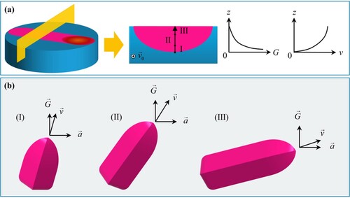
In the early stage of solidification, the as-sintered Al2O3–ZrO2 ceramic was used as the polycrystalline substrate and the Al2O3–ZrO2 eutectic formed a large number of random orientation crystal nuclei on the surface through heterogeneous nucleation, which is mainly due to the heredity of random orientation from the as-sintered polycrystal. Herein, the ratio of G/V gradually decreases from the interface between the melt pool and the substrate to the surface of the nanoeutectic layer, as shown in (a). The eutectic is grown in planar along the inverse heat transfer direction, as shown in (a), due to an extreme ratio of G/V at the interface. As the solidification progresses, V gradually increases and G/V gradually decreases, which induces the eutectic growth transition from planar to cellular. Limited by the growth rate at the interface, the growth direction of the eutectic is mainly dominated by heat flow. Based on the orientation nucleation mechanism, the crystal nuclei whose orientation deviates from the thermal diffusion direction are gradually eliminated, while the columnar eutectic, which is close to the direction of heat flow and perpendicular to the substrate, is finally retained. Moreover, the growth direction () of the columnar eutectic is mainly dominated by the dual factors of the heat flow direction (
) and the crystal preferred orientation (
) and when there is a significant difference between the two directions, it will gradually change from the former to the latter with increasing the growth rate, as shown in (b). When the eutectic growth reaches the near-surface region, the oriented columnar eutectic transforms into the equiaxed eutectic, which is mainly due to the following two aspects: (a) the temperature gradient of the solidified layer at surface area is almost the lowest with attenuation; (b) due to continuous laser irradiation, the melt near the surface has a high degree of supercooling when it solidifies, resulting in the forming of small and randomly distributed eutectic cells.
Figure 5. Schematic illustration of (a) the distribution of growth rate and temperature gradient in thickness direction, (b) the relationship between crystallographic orientation and heat flow direction of faceted cells.
Mechanism of eutectic microstructure refinement
In our previous work, the difference between the JH model and the Trivedi-Magnin-Kurz (TMK) model is evaluated to predict the eutectic spacing. In the TMK model, the relationship between the eutectic spacing (λ) and the growth rate (V) can be expressed as [Citation58]:
(6)
(6) where the parameters of aL and QL are given by:
(7)
(7)
(8)
(8)
(9)
(9)
(10)
(10) where Γi, θi and fi, with i = α or β phase (α = Al2O3 and β = ZrO2), are the Gibbs–Thomson parameter, contact angle and volume fraction, respectively. In Al2O3–ZrO2 binary eutectic system, the solute distribution coefficients of Al2O3 and ZrO2 phases are equal, which means kα = kβ = k = 0. C0 is the composition difference between α and β phases at the eutectic tie-line and D is the solute diffusion coefficient in the eutectic melt. In the case of oxy-acetylene flame remelting, to obtain the same eutectic spacing, the supercooling predicted by the TMK model and the JH model is similar, but the growth rate predicted by the TMK model is much higher than that by the JH model. This difference is ascribed to the model assumptions, that is, the TMK model is only suitable for rapid solidification with a high Péclet number (p ≫ 1). In combination with Al2O3–ZrO2 eutectic ceramics prepared by other methods and the experimental results, the relationship between the actual eutectic spacing and the growth rate is more in line with the JH model, which can be shortly expressed as [Citation59]:
(11)
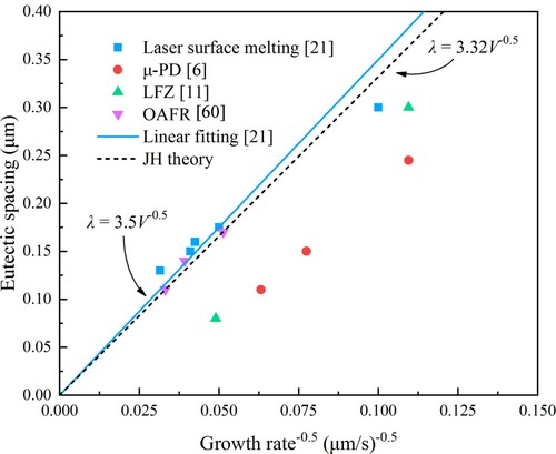
(11) where k is a constant coefficient and n is an exponent of growth rate. Consequently, in laser surface melting with a similar solidification process, the JH model may also be more applicable. This has been confirmed in Ref. [Citation21]. From the bottom of the molten pool to the surface, the eutectic spacing gradually decreases with a gradual increase of the solidification rate. Assuming that the temperature gradient is constant, the growth rate exponent (n) obtained by linear regression analysis is 0.4, which is very close to 0.5 predicted by the JH theory [Citation60,Citation61]. Moreover, the variations of average eutectic spacing with V−0.5 are basically linear, while the proportionality constant of 3.5 is also close to the theoretical value (Kr/Kc)0.5 and the fitting values by other researchers [Citation17,Citation57]. presents the dependence of eutectic spacing on the growth rate for Al2O3–ZrO2 binary eutectic, which conforms to the above results.
Figure 6. The dependence of eutectic spacing on growth rate for Al2O3–ZrO2 binary eutectic.
The refinement of the eutectic microstructure can be interpreted by supercooling and nucleation. According to classical nucleation theory, the nucleation rate (I) is given by [Citation52]:
(12)
(12)
(13)
(13) where I0 is a pre-exponential factor, σ is interface energy between solid and liquid phase, Tl is the liquidus temperature, ΔH is the latent heat of fusion, k is the Boltzman constant, f(θ) is the wetting angle factor, R is gas constant, Q is the activation energy of diffusion. Since the accurate values of I0 and θ are difficult to be obtained currently, it is assumed that I0 = 1041. In addition, for homogeneous nucleation, the wetting angle factor f(θ) = 1, while as far as heterogeneous nucleation, f(θ) is assumed to be 0.05. Relevant physical parameters of Al2O3 and ZrO2 adopted in the calculation are given in . In fact, the calculated results of nucleation rate are the same as that in oxy-acetylene flame remelting, as shown in , due to the similarity of the solidification conditions [Citation62]. The homogeneous nucleation rate of ZrO2 is slightly lower than that of Al2O3, which indicates that in a completely uniform melt, Al2O3 will preferentially precipitate from the melt as primary crystal nuclei. Additionally, when there are solid impurities or primary dendrites in the melt, the nucleation rate will increase significantly through heterogeneous nucleation. As the supercooling increases, the nucleation rate gradually increases. Not only that, the critical nucleus radius (r*) and the critical activation energy (ΔG*), which should be overcome, can be expressed as [Citation54]:
(14)
(14)
(15)
(15) where Tm is the melting point, Lm is the latent heat of fusion and γ is the interfacial energy of radius r*. Continuous laser irradiation will reduce the initial embryos that exist in the melt, which may result in the increase of r* and ΔG*. On the contrary, with the growth rate increasing, the critical nucleus radius and the critical activation energy will decrease due to the rise of supercooling. The variation of I, r*and ΔG* leads to the refinement of the eutectic microstructure from the bottom of the molten pool to the surface [Citation60].
Figure 7. The calculated heterogeneous and homogeneous nucleation rates of both Al2O3 and ZrO2 phases in Al2O3–ZrO2 eutectic as a function of supercooling [Citation62]. Reproduced with permission from Ref. [Citation62], © Elsevier Ltd and Techna Group S.r.l. 2018.
![Figure 7. The calculated heterogeneous and homogeneous nucleation rates of both Al2O3 and ZrO2 phases in Al2O3–ZrO2 eutectic as a function of supercooling [Citation62]. Reproduced with permission from Ref. [Citation62], © Elsevier Ltd and Techna Group S.r.l. 2018.](/cms/asset/84628cee-27a5-461c-af5e-be42b582d2d2/thts_a_2026046_f0007_oc.jpg)
Table 1. Physical parameters of Al2O3–ZrO2 eutectic used for the calculation of nucleation rates.
Optimization of processing parameters
Laser type
Although many types of lasers, which are considered as the most important part, have been used in ceramic preparation and surface engineerings, such as CO2 laser, solid-state laser, diode lasers and fiber laser, the influence and selection principles are not clear enough. Lasers are highly concentrated monochromatic light. The most important difference between the different lasers used in ceramic processing is the wavelength, which of the CO2 laser is 10.6 μm, and commonly the latter three are all around 1 μm (Yb:YAG 1.064 μm, diode laser 0.94 μm, and fiber laser 1.075 μm). Lawrence et al. [Citation66] studied the differences in the interaction of CO2 laser, Nd:YAG laser, excimer laser and high-power diode laser with SiO2–Al2O3 ceramics. The approximation of absorption length for each laser was calculated based on the Beer–Lambert’s law in the laser ablation experiment and revealed a significant difference [Citation35]. The ratio of different melt depths was similar to those of different absorption lengths in the condition of the same power density, while the absorptances of different lasers were similar. Therefore, the absorption length can be the primary influencing factor on the melt depth [Citation67]. Because of short wavelength of the excimer laser, the resolidification phenomenon could not be found [Citation66]. Nikolay et al. [Citation68] tested the absorptivity of different powders for CO2 laser and Nd:YAG laser, and found that the absorptivity of oxide powders such as Al2O3 for CO2 laser is as high as 90%. Therefore, the CO2 laser can melt ceramics at a lower irradiation intensity, which makes it the most widely used in laser surface melting of ceramic materials since the last century [Citation57]. Although the diode laser has mediocre absorptivity for ceramics, there are still many applications [Citation69]. Merino et al. [Citation19] fabricated a high-quality NiO–YSZ (yttria-stabilized zirconia) eutectic layer on the surface of as-sintered ceramic by a high-power diode laser. Ester et al. [Citation18] doped a small amount of Mn2O3 into the ceramic to improve the absorptivity. In our research, a Yb:YAG solid-state laser, which has the characteristics of high energy density, low impact pressure and easy operation, was used to produce a series of nanoeutectic layers with different thickness and microstructure.
The temperature on the ceramic surface absorbing laser irradiation will rise rapidly, which may result in cracks due to the intrinsic brittleness and low thermal shock resistance of oxide ceramics. Interestingly, in the combined laser processing treatment, a high-power CO2 laser with a small beam spot can be used as the main heating source, while a low power diode laser with a large beam spot can be used as the auxiliary preheating source, which can reduce the surface thermal gradient, thus preventing cracking [Citation70]. This method is also used in selective laser melting and the combination of laser sources can be various (e.g. Nd:YAG and CO2 lasers) [Citation71]. Nevertheless, it requires the alignment of the two beams and the strict requirement on the position of the laser, which increases the complexity of the process [Citation26].
The Gaussian beam modes and the beam quality factor affect the intensity distribution of the laser. The high-order mode laser has a wide expansion, which can form a large-scale uniform heating area on the ceramic surface. While in the low-order mode, the laser expansion is narrow, which results in high energy in the center and melts or even vaporizes the material. Shukla et al. [Citation72] compared the difference between CO2 laser and fiber laser when processing the Si3N4 ceramic surface. The threshold of cracking differs because of the laser wavelength, Gaussian beam modes and beam quality factor. Therefore, a comprehensive evaluation on the effect of laser irradiation on ceramics is the basic work that should be completed.
Laser power and scanning rate
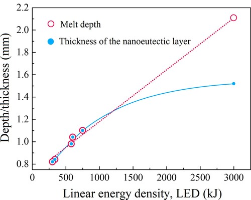
Laser power P and scanning rate V0 are the most important processing parameters that affect the state of the melt pool and the microstructure of the eutectic layer. Establishing the relationship between the processing parameters and the geometry and depth of the melt pool is of great significance for improving the performance of the nanoeutectic layer and realizing the automatic control of the process. The evolution of the melt pool depth with the laser power and scanning rate was reported by some researchers [Citation57,Citation73]. It is worth noting that due to the different experimental conditions (materials and light sources), the actual absorptivity is not the same. As a result, the energy density cannot be used as a universal index for comparison. At the same scanning rate, the depth of the melt pool increases with increasing the energy density. In the experiment of Ester et al. [Citation18], a linear laser beam (1 × 10 mm2) was used, which completely covered the width of the sample, so the linear power density could be used as the abscissa. The maximum melt pool depth and the laser power density are almost a linear relation. The fitted straight lines have a common intercept, which means that there is a critical power density at this preheating temperature, below which the material cannot be melted [Citation18]. shows the variations in the thickness of the Al2O3–ZrO2 nanoeutectic ceramic layer with laser power and scanning rate. The thickness and the depth gradually increase as the laser scanning rate decreases from 1.0 to 0.1 mm s−1 at a constant laser power of 300 W. Particularly, when the scanning rate is quite low, the thickness is not the same as the melt depth. This is because the heat input rate is much higher than the heat transfer rate in the melt at this time. The accumulation of heat leads to a rapid increase in the temperature, which finally results in the volatilization loss in the melt pool. The linear energy density (LED), with the expression of LED = P/V0, is introduced to evaluate the average applied energy per unit length, which is determined by laser power and scanning rate [Citation21]. In this case, the nanoeutectic layer thickness and melt depth can be the function of LED, as shown in . With the increase of LED, the former increases exponentially, while the latter shows a nearly linear growth.
Figure 8. Variations in the thickness of the Al2O3–ZrO2 nanoeutectic ceramic layer as a function of laser power and scanning rate.
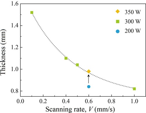
Figure 9. Variations in the thickness of the Al2O3–ZrO2 nanoeutectic ceramic layer and the melt depth as a function of linear energy density.
There are mainly two melting modes when laser irradiation strikes the surface of materials. One is the ‘keyhole’ mode characterized by a large penetration depth due to high laser intensity. The alternative is the conduction mode when the energy is moderate, in which the melt pool is wide and shallow [Citation74]. It can be demarcated by the aspect ratio of the molten pool with 0.5 as the threshold. In the study of Liu et al. [Citation24], the aspect ratio in selective laser melting was lower than 0.5, and the same situation was observed in the study of Bourban et al. [Citation57]. In our research, the maximum aspect ratio of the molten pool was 0.28 when the LED reached the maximum value of 3000 kJ m−1. The transition from conduction mode to keyhole mode with increasing the laser intensity cannot be observed in these studies. Based on the above, it can be judged that the melting mode during laser processing of Al2O3-based ceramics under ordinary conditions is the conduction mode, that the heat transfer mechanism mainly consists of conduction and convection within the molten pool. In this case, the surface geometry of molten pool can be qualitatively predicted by the thermal Péclet number (Pt) [Citation57] related to thermal diffusion distance, which can be expressed in this system as:
(16)
(16) where RL is the radius of the laser beam (m), Vs is the local solidification rate (m·s−1), and a is the thermal diffusivity (m2·s−1). A small Pt means that the shape is close to a circle. When Pt gradually increases, the molten pool will elongate in the direction of processing. To obtain more accurate predictions needs numerical simulation.
The quality of the solidified layer is closely related to the energy absorbed by the surface. Insufficient laser intensity will lead to a deficient depth of the molten pool or even the material cannot be completely melted. Contrariwise, if the absorbed energy is excessive, the molten pool may become unstable and the vaporization of the melt may be aggravated. As a consequence, a poor-quality surface with roughness, pores, etc. could be induced after laser surface treatment. The instability of the melt and the balling phenomenon may cause more serious consequences in selective laser melting. The new powder layer may not be uniformly deposited on the formerly processed layer, which will interfere with or even interrupt the liquid track. Then, a series of harmful defects such as cracks, pores and delamination will be formed, especially at high scanning rates [Citation75,Citation76]. Qiu et al. [Citation77] simulated and verified the instability of the molten pool caused by spatter and vaporization of the melt by computational fluid dynamics (CFD) calculation and high speed imaging observation. This spatter phenomenon is believed to be the result of complex factors, including Marangoni effect, recoil pressure caused by vaporization, and gas expansion. In addition, the vaporization of the melt will also affect the thermal gradient by energy dissipation, resulting in changes in the Marangoni force and internal convection. Note that, due to different vapor pressures of the components in multiphase ceramics, selected evaporation will occur during the laser melting process, causing the composition to deviate from the original proportion, which is more serious at a low scanning rate [Citation78]. This should be taken into consideration when preparing eutectic oxide ceramics.
Atmosphere and preheating
The eutectic ceramics grown from the melt usually contain pores, which are prone to cause local stress concentration and crack initiation. Therefore, it is necessary to ascertain the formation mechanism of solidification defects. There are two sources of pores in the solidified ceramic layer: (i) since the ceramic melt has a high viscosity and the gas solubility is higher than that of the solid, lots of gas will be precipitated during solidification [Citation79]; (ii) there are initial pores in the precursor (as-sintered oxide ceramics) [Citation80]. The movement of bubbles in the melt is controlled by buoyancy, thermocapillary force and viscous force. In order to reduce the interfacial energy, the bubbles will migrate from the low-temperature area (inside the melt) with high surface tension to the high-temperature area (the surface of the melt) with low surface tension. This motion is called Marangoni migration [Citation81]. If the velocity of bubbles is lower than the migration rate of the solidification front, the bubbles will be trapped and stay as a pore in the solidified material. Triantafyllidis et al. [Citation73] derived a simple model that described the formation of pores at the molten pool boundary, as shown in . The flow of the melt is regarded as driven by thermocapillary, which is induced by surface tension gradient (caused by the temperature gradient and assumed to be linear). The bubble velocity vector formed at the interface mainly consists of three parts: (i) velocity of convective fluid flow; (ii) vertical upward thermocapillary-induced velocity component, which is induced by local temperature gradient with the same direction; (iii) vertical upward buoyancy component. The local interface solidification velocity adopts the Neumann solutions of the Stefan problem, ignoring the liquid temperature gradient and supercooling effect, and its direction is the solidification interface normal. By comparing the composition of the bubble velocity in the normal direction of the interface with the local solidification velocity, it can be judged whether the bubble is trapped or not. Not only that, this model can predict the possible maximum pore diameter and its location along the molten pool boundary. Su et al. [Citation81] studied the trapping and growth along the solidification direction of bubbles at the interface in the LFZ process. Yan and Huang et al. [Citation82,Citation83] studied the shrinkage cavities in laser directed energy deposition method, which is different from the bubble-induced pores. The melt adheres to the surrounding materials for solidification, and the central area cannot be completely filled without timely supplement from the liquid phase at a high solidification rate. Finally, the voids expand into shrinkage cavities due to the further contraction of the surroundings. The above results have confirmed that increasing the solidification rate will decrease the melt temperature and increase the viscosity, and slow down the bubbles migration, resulting in more trapped pores. However, to get fine eutectic ceramics with small eutectic spacing, a high growth rate is necessary. It is noted that the total porosity may decrease at a very high solidification rate, possibly because the liquid phase has no time to dissolve more external gases [Citation20]. Thus, it is an alluring and meaningful subject that reduces the porosity and broadens the range of process parameters for forming defect-free structures.
Figure 10. Schematic diagram of Marangoni migration and the velocity of the bubble [Citation73]. Reproduced with permission from Ref. [Citation73], © The American Ceramic Society.
![Figure 10. Schematic diagram of Marangoni migration and the velocity of the bubble [Citation73]. Reproduced with permission from Ref. [Citation73], © The American Ceramic Society.](/cms/asset/00dea31c-83c0-4939-901a-6e62baa59660/thts_a_2026046_f0010_oc.jpg)
The atmosphere, which contacts the molten pool and the untreated part, will participate in the process of dissolution and precipitation of gases in the solid and liquid phases. Some empirical conclusions were drawn by Oliete et al. [Citation84]: (i) the oxygen partial pressure is a key factor affecting the generation of pores, and as it increases, the porosity and pore size will increase; (ii) the use of non-oxidant atmosphere (nitrogen, argon or vacuum) can obtain samples with no or few pores at high growth rates; (iii) argon may not be as effective as nitrogen or vacuum in reducing porosity. Laser surface melting of oxide ceramics in an oxygen-deficient atmosphere will generate oxygen vacancies, which may change the color of ceramics macroscopically. Such oxygen vacancies can be eliminated by annealing in air [Citation85]. Not only that, the transition from t-ZrO2 to m-ZrO2 will be inhibited in an oxygen-deficient environment. This is because the coordination number of zirconium is 8 and 7 in tetragonal and monoclinic phases, respectively, which means that oxygen ions are bound to displace during the phase transition of zirconia [Citation86]. Stable and inert nitrogen under normal conditions will react with ZrO2 due to high energy laser irradiation, and the product of ZrN may change the structure and properties of the surface [Citation87]. However, in laser surface processing of multiphase composite ceramics containing ZrO2, it seems that the influence of nitrogen has not been considered, even though nitrogen has been used as a working atmosphere in some studies [Citation88]. It is worth noting that although non-oxidant atmospheres have been widely used to obtain eutectic ceramics at a high solidification rate [Citation88,Citation89], the mechanism for inhibiting the formation of pores is still unclear. This requires more information on the constituent and position of bubbles.
High melting point and low thermal conductivity of oxide ceramics result in a large thermal shock during laser surface melting. In more detail, large tensile stresses between adjacent treated areas owing to high-temperature gradient and cooling rate. In addition, the constraints imposed by the untreated zone on the treated part may also cause stress [Citation26]. Cracking will occur when the tensile stress exceeds the limit. Restricted by heat transfer and material strength, the processing parameters required to obtain a crack-free surface are very demanding without other auxiliary means [Citation26,Citation90]. By preheating a wide range of substrates to reduce the thermal gradient, crack-free ceramic coatings, surfaces or bulks can be prepared in more situations. For instance, as the preheating temperature increases, extensive cracking of the ceramic substrate caused by thermal shock and the microcracks caused by thermal stress between the resolidified layer and the remaining substrate will gradually disappear during laser surface melting of Al2O3–ZrO2 ceramics. When the preheating temperature is above 1200°C, the thermal stress can be effectively relaxed and accommodated, which enables a dense and 400 μm thick eutectic layer without cracks, delamination and other defects [Citation29]. Gusarov et al. [Citation91] proposed a simple thermoelastic model for calculating residual stress, which can explain the effect of preheating. As mentioned above, the auxiliary laser in a combined laser system can play a preheating role. Compared with substrate preheating, it can directly heat the area to be processed with a higher temperature, although the complexity is increased. By preheating the material to at least 1600°C, crack formation in Al2O3–ZrO2 parts with any complex shaped geometries can be avoided during the SLM process. Moreover, the preheating of the raw powder before being sent also needs to be considered, because the hyperthermal surface contacting the cold powder may crack [Citation71,Citation92]. For single-component ceramics with a high melting point such as ZrO2 (∼2700°C), a higher preheating temperature is required to prevent the destructive vertical perforative cracks [Citation93]. In addition, preheating may affect the structural phase transition [Citation93,Citation94], although it is not clear whether this effect occurs during solidification or not. Recently, the cracks and pores in Al2O3–ZrO2 eutectic ceramics were reduced by doping SiC particles and by ultrasonic-assisted treatment [Citation95,Citation96]. These new attempts change the state of molten pool and ultimately affect the interfacial structure of eutectic ceramics, which definitely inspires more imagination.
Performances and applications
The excellent strength retention of oxide eutectic ceramics at high temperatures benefits from the clear and strong phase interface, which has almost no defects such as amorphous phase, impurities and pores, and forms an entangled continuous network structure. Unlike the grain boundaries in the as-sintered ceramics, such phase interfaces are difficult to slip at elevated temperatures. Furthermore, the ultrafine phase structure and inherent thermoelastic stress field can interact with the propagating crack, which may cause the cracks to stop or deflect [Citation1]. The performances of oxide eutectic ceramics, prepared by traditional directional solidification methods and laser additive manufacturing, have been summarized by many researchers. Directionally solidified eutectic ceramics (DSEC) stand out by their impressive flexure strength, especially at high temperatures. The flexural strength of oxide eutectic ceramics, produced by additive manufacturing including SLM, laser engineered net shaping (LENS) and other technologies, is already close to that of as-sintered ceramics, and the fracture toughness gradually overtakes that of DSEC [Citation1,Citation51,Citation97]. lists some properties of oxide eutectic ceramics prepared by different methods. However, they are not the focus of this paper. By laser surface melting, a nanoeutectic layer is formed on the surface of oxide ceramics with eutectic composition. The temperature gradient and the solidification rate have the characteristics of gradient distribution at different depths of molten pool and cannot be independently controlled. This makes the microstructure of the solidified layer a gradient distribution feature in a thickness direction, which will inevitably lead to a difference in the properties of materials at different depths. Later, mechanical properties of the nanoeutectic layer will be discussed in conjunction with the results reported in the open literature.
Table 2. Eutectic systems, fabricating methods, flexural strength and fracture toughness of Al2O3-based eutectic ceramics.
There are still several reports on the eutectic modification of ceramic surfaces in functional materials. An example is the NiO–YSZ system applied to solid oxide fuel cells [Citation104]. Both anodes of the NiO–YSZ/YSZ/NiO–YSZ symmetric cells were processed by laser melting treatment to generate NiO–YSZ eutectic layers, which were then reduced in a humidified hydrogen atmosphere at 800°C. Finally, Ni–YSZ samples were obtained. Due to the uniform eutectic structure, the reduced Ni–YSZ samples showed better connectivity between Ni particles. The microstructural optimization led to a reduction in polarization resistance. This method can also be used for surface texturing and the design of functional gradient materials [Citation19,Citation90].
Hardness and elastic modulus
The nanohardness distribution of surface-nanocrystallized Al2O3–ZrO2 eutectic layer with a thickness of 1000 μm was reported in our previous study, as shown in [Citation28]. The nanohardness of the nanoeutectic layer decreases from 26.1 to 22.2 GPa as the depth increases. This is mainly a consequence of the gradual decrease in the characteristic dimension of irregular and coarse tissue between the cellular structures from the bottom to the surface of the eutectic layer, as shown in . The irregular tissue is the transitional structure formed by successive precipitation of residual Al2O3 and ZrO2 in the melt after the eutectic cells grow up into contact. These final solidified melts may have deviated from the eutectic composition [Citation105]. However, Liu et al. [Citation101] seemed to have observed an opposite phenomenon in Al2O3–GdAlO3–ZrO2 eutectic ceramics prepared by SLM. In a single track solidified layer, the hardness of the eutectic ceramic slightly increased as the depth increased. This result is somewhat counterintuitive. By analyzing the composition of the eutectic layer at different depths, they attributed the change in hardness to the alteration in volume fraction of the constituent phases. It is believed that the solidification rate is too high to maintain a planar S/L interface and the growth at eutectic composition, resulting in the composition segregation [Citation106]. Overall, the change in hardness may be the consequence of two factors: (i) composition segregation caused by rapid solidification; (ii) microstructure difference caused by different solidification conditions.
Figure 11. Nanohardness distribution of the Al2O3–ZrO2 nanoeutectic layer formed by laser surface melting as a function of the distance from the surface [Citation28]. Reproduced with permission from Ref. [Citation28], © Elsevier Ltd and Techna Group S.r.l. 2019.
![Figure 11. Nanohardness distribution of the Al2O3–ZrO2 nanoeutectic layer formed by laser surface melting as a function of the distance from the surface [Citation28]. Reproduced with permission from Ref. [Citation28], © Elsevier Ltd and Techna Group S.r.l. 2019.](/cms/asset/d5363479-7c3a-4964-9fcc-00fa93f6ecdd/thts_a_2026046_f0011_oc.jpg)
The measured elastic modulus has almost the same trend as the hardness. It gradually increases from the substrate to the near-surface area of the eutectic layer. At a distance of about 100–600 μm from the surface, it is about 320–360 GPa, which is consistent with the theoretical value of 330 GPa obtained by the rule of mixing (ROM) approximately. The hardness and elastic modulus of the as-sintered ceramic substrate are 18.7 and 300 GPa, respectively, which are both clearly smaller than those of the nanoeutectic layer. Furthermore, the friction coefficient of the nanoeutectic layer is lower than that of traditional as-sintered ceramics, and the wear rate is about an order of magnitude smaller than that of the latter [Citation18]. Therefore, laser surface melting provides a promising potential in enhancing the surface hardness and wear resistance of oxide ceramics for sliding ceramic parts.
Fracture toughness
Most of the fracture toughness measurements of oxide eutectic ceramics is obtained by the indentation testing. Under a small load, Palmqvist cracks are formed, which can be used to calculate the fracture toughness KIC. The equation proposed by Niihara et al. [Citation107] is expressed as:
(17)
(17) where Hv is the hardness, E is the elasticity modulus, l is the crack length, a is the indent half-diagonal and ϕ is a constraint factor, respectively. The KIC obtained by this method is only a rough estimate, but it can be used for comparison with other reported results of the same standard. Based on the laser surface melting method, many eutectic ceramic layers were prepared, and their fracture toughness values are listed in [Citation18,Citation63,Citation108,Citation109]. The surface eutectic layer of Al2O3–ZrO2(Y2O3) prepared by Ester et al. [Citation18] has a high fracture toughness of 6–7 MPa·m1/2. As compared with , the fracture toughness approaches the value obtained by DSEC. The high fracture toughness of eutectic ceramics mainly benefits from two points: (a) thermal residual stress due to different coefficients of thermal expansion; (b) ultrafine and curved phase interfaces [Citation1,Citation110]. As a result, the crack energy will be consumed and further propagation will be prevented by crack branching, deflection and bridging, which have been widely investigated [Citation52,Citation62,Citation111]. Furthermore, Liu et al. [Citation101] found that the fracture toughness of ternary eutectic ceramics prepared by SLM decreases from the bottom to the top of the molten pool. Reasons were taken into consideration to be the reduction of the phases enduring compressive stress and microstructure size of phases, while the residual stress is higher and the effect of crack arrest is more obvious in eutectic ceramics with relatively large microstructure dimension [Citation100]. In fact, KIC is also related to the defects, but it can usually be ignored in the eutectic layer due to the low porosity.
Table 3. Fracture toughness of Al2O3-based eutectic ceramics prepared by laser surface melting method.
Summary
Laser surface nanocrystallization of oxide ceramics with eutectic composition has shown the feasibility and sufficient superiority. The nanoeutectic ceramic layers formed on the surface of the as-sintered ceramics have better mechanical performance. Convenience and repeatability make it an attractive method of surface modification, although the microstructural optimization and reduction in defects require continuous adjustment of processing parameters. However, many interpretations of the solidification process and strengthening/toughening mechanisms lack more intuitionistic evidence, such as the real motion of bubbles in molten pool and the crack propagation in the interior of nanoeutectics, which demands the firm support from advanced testing and characterization technologies. Numerical simulation has been widely used to calculate the melt state, such as the melt shape, temperature field and thermal stress. The complexity of molten pool determines the difficulty of establishing a perfect model, which requires further research on heat transfer and the melting-solidification process. Moreover, the in-situ micromechanical testing technique, which provides insights into deformation and fracture pathways, has proven effective for revealing strengthening–toughening mechanisms of eutectic ceramics. At present, the applications of this method are still limited, especially in the field of functional ceramics, and related study deserves more efforts in the future.
Disclosure statement
No potential conflict of interest was reported by the author(s).
Additional information
Funding
References
- Llorca J, Orera V. Directionally solidified eutectic ceramic oxides. Prog Mater Sci. 2006;51(6):711–809.
- Nakagawa N, Ohtsubo H, Mitani A, et al. High temperature strength and thermal stability for melt growth composite. J Eur Ceram Soc. 2005;25(8):1251–1257.
- Yamada S, Yoshimura M, Sakata S-I, et al. Colony structure in Ce-doped Al2O3/YAG eutectic systems grown by vertical bridgman technique. J Cryst Growth. 2016;448:1–5.
- Yoshimura M, Sakata S-I, Iba H, et al. Vertical bridgman growth of Al2O3/YAG:Ce melt growth composite. J Cryst Growth. 2015;416:100–105.
- Yoshikawa A, Epelbaum BM, Hasegawa K, et al. Microstructures in oxide eutectic fibers grown by a modified micro-pulling-down method. J Cryst Growth. 1999;205(3):305–316.
- Lee JH, Yoshikawa A, Durbin SD, et al. Microstructure of Al2O3/ZrO2 eutectic fibers grown by the micro-pulling down method. J Cryst Growth. 2001;222(4):791–796.
- Ohashi Y, Yasui N, Suzuki T, et al. Orientation relationships of unidirectionally aligned GdAlO3/Al2O3 eutectic fibers. J Eur Ceram Soc. 2014;34(15):3849–3857.
- Benamara O, Cherif M, Duffar T, et al. Microstructure and crystallography of Al2O3–Y3Al5O12–ZrO2 ternary eutectic oxide grown by the micropulling down technique. J Cryst Growth. 2015;429:27–34.
- Matson LE, Hecht N. Microstructural stability and mechanical properties of directionally solidified alumina/YAG eutectic monofilaments. J Eur Ceram Soc. 1999;19(13-14):2487–2501.
- Carroz L, Duffar T. Tuning the sapphire EFG process to the growth of Al2O3/YAG/ZrO2:Y eutectic. J Cryst Growth. 2018;489:5–10.
- Peña JI, Merino RI, Harlan NR, et al. Microstructure of Y2O3 doped Al2O3–ZrO2 eutectics grown by the laser floating zone method. J Eur Ceram Soc. 2002;22(14-15):2595–2602.
- Mesa MC, Oliete PB, Merino RI, et al. Optical absorption and selective thermal emission in directionally solidified Al2O3-Er3Al5O12 and Al2O3-Er3Al5O12-ZrO2 eutectics. J Eur Ceram Soc. 2013;33(13-14):2587–2596.
- Su H, Ren Q, Zhang J, et al. Microstructures and mechanical properties of directionally solidified Al2O3/GdAlO3 eutectic ceramic by laser floating zone melting with high temperature gradient. J Eur Ceram Soc. 2017;37(4):1617–1626.
- Dabkowska HA, Dabkowski AB. Crystal growth of oxides by optical floating zone technique. In: Springer handbook of crystal growth. Berlin: Springer; 2010. p. 367–391.
- Wang X, Tian Z, Zhang W, et al. Mechanical properties of directionally solidified Al2O3/Y3Al5O12 eutectic ceramic prepared by optical floating zone technique. J Eur Ceram Soc. 2018;38(10):3610–3617.
- Su H, Zhang J, Deng Y, et al. A modified preparation technique and characterization of directionally solidified Al2O3/Y3Al5O12 eutectic in situ composites. Scripta Mater. 2009;60(6):362–365.
- Larrea A, de la Fuente GF, Merino RI, et al. Zro2–Al2O3 eutectic plates produced by laser zone melting. J Eur Ceram Soc. 2002;22(2):191–198.
- Ester FJ, Merino RI, Pastor JY, et al. Surface modification of ZrO2–Al2O3(Y2O3) eutectic oxides by laser melting: processing and wear resistance. J Am Ceram Soc. 2008;91(11):3552–3559.
- Merino RI, Peña JI, Orera VM. Compositionally graded YSZ–NiO composites by surface laser melting. J Eur Ceram Soc. 2010;30(2):147–152.
- Ester FJ, Larrea A, Merino RI. Processing and microstructural study of surface laser remelted Al2O3–YSZ–YAG eutectic plates. J Eur Ceram Soc. 2011;31(7):1257–1268.
- Wang Z-G, Ouyang J-H, Wang Y-J, et al. Microstructural characterization of nanostructured Al2O3–ZrO2 eutectic layer by laser rapid solidification method. Appl Surf Sci. 2019;476:335–341.
- Tong L. Growth of high-quality Y2O3–ZrO2 single-crystal optical fibers for ultra-high-temperature fiber-optic sensors. J Cryst Growth. 2000;217(3):281–286.
- Sola D, Ester FJ, Oliete PB, et al. Study of the stability of the molten zone and the stresses induced during the growth of Al2O3/Y3Al5O12 eutectic composite by the laser floating zone technique. J Eur Ceram Soc. 2011;31(7):1211–1218.
- Liu H, Su H, Shen Z, et al. Effect of scanning speed on the solidification process of Al2O3/GdAlO3/ZrO2 eutectic ceramics in a single track by selective laser melting. Ceram Int. 2019;45(14):17252–17257.
- Bradley L, Li L, Stott FH. Flame-assisted laser surface treatment of refractory materials for crack-free densification. Mater Sci Eng A. 2000;278(1-2):204–212.
- Triantafyllidis D, Li L, Stott FH. Crack-free densification of ceramics by laser surface treatment. Surf Coat Technol. 2006;201(6):3163–3173.
- Wang SH, Liu JC. Comparison of Al2O3/Er3Al5O12/ZrO2 ceramics with eutectic composition prepared using hot-pressing sintering and melt growing. Mater Sci Eng A. 2020;774:138932.
- Wang Z-G, Ouyang J-H, Ma Y-H, et al. Grain size dependence, mechanical properties and surface nanoeutectic modification of Al2O3-ZrO2 ceramic. Ceram Int. 2019;45(11):14297–14304.
- Gurauskis J, Lennikov V, de la Fuente GF, et al. Laser-assisted, crack-free surface melting of large eutectic ceramic bodies. J Eur Ceram Soc. 2011;31(7):1251–1256.
- Ökten K, Biyikoğlu A. Development of thermal model for the determination of SLM process parameters. Opt Laser Technol. 2021;137:106825.
- Guan X, Zhao YF. Modeling of the laser powder-based directed energy deposition process for additive manufacturing: a review. Int J Adv Manuf Technol. 2020;107(5-6):1959–1982.
- Papazoglou EL, Karkalos NE, Karmiris-Obratański P, et al. On the modeling and simulation of SLM and SLS for metal and polymer powders: A review. Arch Comput Methods Eng. 2021:1–33. https://doi.org/https://doi.org/10.1007/s11831-021-09601-x.
- Zhang ZY, Liu ZC, Wu DZ. Prediction of melt pool temperature in directed energy deposition using machine learning. Addit Manuf. 2021;37:101692.
- Li JF, Li L, Stott FH. Comparison of volumetric and surface heating sources in the modeling of laser melting of ceramic materials. Int J Heat Mass Transfer. 2004;47(6-7):1159–1174.
- Lawrence J, Li L. Determination of the absorption length of CO2 and high power diode laser radiation for a high volume alumina-based refractory material. Appl Surf Sci. 2000;168(1-4):71–74.
- Li JF, Li L, Stott FH. Thermal stresses and their implication on cracking during laser melting of ceramic materials. Acta Mater. 2004;52(14):4385–4398.
- Li JF, Li L, Stott FH. A three-dimensional numerical model for a convection–diffusion phase change process during laser melting of ceramic materials. Int J Heat Mass Transfer. 2004;47(25):5523–5539.
- Bityukov VK, Petrov VA, Smirnov IV. The effect of flux density on the formation of temperature field in alumina under conditions of heating by concentrated laser radiation. High Temp+. 2009;47(4):559–565.
- Hao L, Lawrence J. Numerical modelling of the laser surface processing of magnesia partially stabilized zirconia by the means of three-dimensional transient finite element analysis. P Roy Soc A-Math Phy. 2005;462(2065):43–57.
- Petrov VA, Titov VE, Vorobyev AY. Numerical simulation of concentrated laser radiation heating of refractory oxides. High Temp-High Press. 1999;31(3):267–274.
- Petrov VA. Thermoradiation characteristics of refractory oxides upon heating by concentrated laser radiation. High Temp+. 2016;54(2):186–196.
- Bityukov VK, Petrov VA. The brightness temperature of aluminum oxide when it is heated by concentrated laser radiation. Meas Tech. 2014;57(6):658–663.
- Gusarov AV, Kruth JP. Modelling of radiation transfer in metallic powders at laser treatment. Int J Heat Mass Transfer. 2005;48(16):3423–3434.
- Gusarov AV, Smurov I. Radiation transfer in metallic powder beds used in laser processing. J Quant Spectrosc Radiat Transfer. 2010;111(17-18):2517–2527.
- Gusarov AV, Yadroitsev I, Bertrand P, et al. Model of radiation and heat transfer in laser-powder interaction zone at selective laser melting. J Heat Transf-Trans ASME. 2009;131(7):072101.
- Chen Q, Guillemot G, Gandin C-A, et al. Three-dimensional finite element thermomechanical modeling of additive manufacturing by selective laser melting for ceramic materials. Addit Manuf. 2017;16:124–137.
- Chen Q, Guillemot G, Gandin C-A, et al. Numerical modelling of the impact of energy distribution and marangoni surface tension on track shape in selective laser melting of ceramic material. Addit Manuf. 2018;21:713–723.
- Ma R, Zhang K, Wei H, et al. Formation mechanism of surface microstructure in selective laser melting of alumina ceramic based on numerical simulation. Chin J Lasers. 2019;46(2):0202002.
- Mizev AI, Schwabe D. Convective instabilities in liquid layers with free upper surface under the action of an inclined temperature gradient. Phys Fluids. 2009;21(11):112102.
- Ghate ND, Shrivastava A. Numerical and experimental investigation of complex surface topography evolution during laser surface modification with raster scan. J Manuf Processes. 2021;69:368–377.
- Orera VM, Peña JI, Oliete PB, et al. Growth of eutectic ceramic structures by directional solidification methods. J Cryst Growth. 2012;360:99–104.
- Fan Z, Zhao Y, Tan Q, et al. Nanostructured Al2O3-YAG-ZrO2 ternary eutectic components prepared by laser engineered net shaping. Acta Mater. 2019;170:24–37.
- Lin X, Cao Y-Q, Wang Z-T, et al. Regular eutectic and anomalous eutectic growth behavior in laser remelting of Ni-30wt%Sn alloys. Acta Mater. 2017;126:210–220.
- Kurz W, Fisher DJ. Fundamentals of solidification. Switzerland: Trans Tech Publication; 1998. p. 71–92.
- Murphy AG, Browne DJ, Mirihanage WU, et al. Combined in situ X-ray radiographic observations and post-solidification metallographic characterisation of eutectic transformations in Al-Cu alloy systems. Acta Mater. 2013;61(12):4559–4571.
- Chen G, Fu X, Luo J, et al. Effect of cooling rate on the microstructure and mechanical properties of melt-grown Al2O3/YAG/ZrO2 eutectic ceramic. J Eur Ceram Soc. 2012;32(16):4195–4204.
- Bourban S, Karapatis N, Hofmann H, et al. Solidification microstructure of laser remelted Al2O3–ZrO2 eutectic. Acta Mater. 1997;45(12):5069–5075.
- Wang Z-G, Ouyang J-H, Ma Y-H, et al. Formation mechanism of a wrinkled and textured Al2O3-ZrO2 nanoeutectic rapidly solidified from oxy-acetylene flame remelting. J Am Ceram Soc. 2019;102(1):63–69.
- Yang X, Zhang J, Su H, et al. Effect of growth rate on rod spacing and undercooling of bridgman-grown Si–TaSi2 eutectic in situ composite. J Alloys Compd. 2013;551:643–648.
- Wang Z-G, Ouyang J-H, Ma Y-H, etal. Enhanced nucleation undercooling and surface self-nanocrystallization of Al2O3-ZrO2(Y2O3) eutectic ceramics. J Eur Ceram Soc. 2019;39(4):1707–1711.
- Jackson K A, Hunt J D. Lamellar and rod eutectic growth. Dyn. Curved Fronts. 1988;236:363–376.
- Wang Z-G, Ouyang J-H, Wang Y-J, et al. Nucleation and epitaxial growth of highly textured Al2O3–ZrO2 nanoeutectic rapidly solidified from oxyacetylene flame remelting. Ceram Int. 2018;44(17):22027–22031.
- Su H, Zhang J, Cui C, et al. Rapid solidification of Al2O3/Y3Al5O12/ZrO2 eutectic in situ composites by laser zone remelting. J Cryst Growth. 2007;307(2):448–456.
- Wang J, Raj R. Estimate of the activation energies for boundary diffusion from rate-controlled sintering of pure alumina, and alumina doped with zirconia or titania. J Am Ceram Soc. 1990;73(5):1172–1175.
- Milsom B, Viola G, Gao Z, et al. The effect of carbon nanotubes on the sintering behaviour of zirconia. J Eur Ceram Soc. 2012;32(16):4149–4156.
- Lawrence J, Li L. On the differences between the beam interaction characteristics of CO2, Nd:YAG, excimer and high power diode lasers with a SiO2/Al2O3 ceramic. Laser Eng. 2002;12(2):81–93.
- Lawrence J. An analysis of the beam interaction characteristics of selected lasers with an alpha-alumina bioceramic. Opt Lasers Eng. 2004;41(3):505–514.
- Tolochko NK, Laoui T, Khlopkov YV, et al. Absorptance of powder materials suitable for laser sintering. Rapid Prototyping J. 2000;6(3):155–160.
- Fan ZQ, Lu MY, Huang H. Selective laser melting of alumina: a single track study. Ceram Int. 2018;44(8):9484–9493.
- Triantafyllidis D, Li L, Stott FH. Surface treatment of alumina-based ceramics using combined laser sources. Appl Surf Sci. 2002;186(1-4):140–144.
- Wilkes J, Hagedorn YC, Meiners W, et al. Additive manufacturing of ZrO2–Al2O3 ceramic components by selective laser melting. Rapid Prototyp J. 2013;19(1):51–57.
- Shukla PP, Lawrence J. A comparative study on the processing parameters during fibre and CO2 laser surface treatments of silicon nitride engineering ceramic. Int J Adv Manuf Technol. 2012;59:143–155.
- Triantafyllidis D, Li L, Stott H. Modeling of boundary porosity formation in laser melting and re-solidification of ceramics. J Am Ceram Soc. 2006;89(4):1286–1294.
- Yang J, Han J, Yu H, et al. Role of molten pool mode on formability, microstructure and mechanical properties of selective laser melted Ti-6Al-4V alloy. Mater Design. 2016;110:558–570.
- Gu D, Hagedorn Y-C, Meiners W, et al. Densification behavior, microstructure evolution, and wear performance of selective laser melting processed commercially pure titanium. Acta Mater. 2012;60(9):3849–3860.
- Attar H, Ehtemam-Haghighi S, Kent D, et al. Comparative study of commercially pure titanium produced by laser engineered net shaping, selective laser melting and casting processes. Mater Sci Eng A. 2017;705:385–393.
- Qiu C, Panwisawas C, Ward M, et al. On the role of melt flow into the surface structure and porosity development during selective laser melting. Acta Mater. 2015;96:72–79.
- Wang AH, Wang WY, Xie CS, et al. Microstructural characteristics of Al2O3-based refractory containing ZrO2 induced by CO2 laser melting. Appl Surf Sci. 2004;221(1-4):293–301.
- Saito M. Gas-bubble formation of ruby single crystals by floating zone method with an infrared radiation convergence type heater. J Cryst Growth. 1985;71(3):664–672.
- Triantafyllidis D, Li L, Stott FH. Mechanisms of porosity formation along the solid/liquid interface during laser melting of ceramics. Appl Surf Sci. 2003;208-209:458–462.
- Su H, Liu Y, Ren Q, et al. Distribution control and formation mechanism of gas inclusions in directionally solidified Al2O3-Er3Al5O12-ZrO2 ternary eutectic ceramic by laser floating zone melting. J Mater Sci Technol. 2021;66:21–27.
- Yan S, Huang Y, Zhao D, et al. 3D printing of nano-scale Al2O3–ZrO2 eutectic ceramic: principle analysis and process optimization of pores. Addit Manuf. 2019;28:120–126.
- Huang Y, Wu D, Zhao D, et al. Investigation of melt-growth alumina/aluminum titanate composite ceramics prepared by directed energy deposition. Int J Extrem Manuf. 2021;3(3):035101.
- Oliete PB, Peña JI. Study of the gas inclusions in Al2O3/Y3Al5O12 and Al2O3/Y3Al5O12/ZrO2 eutectic fibers grown by laser floating zone. J Cryst Growth. 2007;304(2):514–519.
- Liu H, Su H, Shen Z, et al. One-step additive manufacturing and microstructure evolution of melt-grown Al2O3/GdAlO3/ZrO2 eutectic ceramics by laser directed energy deposition. J Eur Ceram Soc. 2021;41(6):3547–3558.
- Guan J, Wang Q, Zhang X, et al. Selective laser melting of yttria-stabilized zirconia. Mater Res Express. 2019;6(1):015402.
- Kathuria YP. Laser surface nitriding of yttria stabilized tetragonal zirconia. Surf Coat Technol. 2007;201(12):5865–5869.
- Mesa MC, Oliete PB, Pastor JY, et al. Mechanical properties up to 1900 K of Al2O3/Er3Al5O12/ZrO2 eutectic ceramics grown by the laser floating zone method. J Eur Ceram Soc. 2014;34(9):2081–2087.
- Ren Q, Su H, Zhang J, et al. Processing, microstructure and performance of Al2O3/Er3Al5O12/ZrO2 ternary eutectic ceramics prepared by laser floating zone melting with ultra-high temperature gradient. Ceram Int. 2018;44(5):4766–4776.
- Campana R, Larrea A, Peña JI, et al. Ni–YSZ cermet micro-tubes with textured surface. J Eur Ceram Soc. 2009;29(1):85–90.
- Gusarov AV, Pavlov M, Smurov I. Residual stresses at laser surface remelting and additive manufacturing. Phys Procedia. 2011;12:248–254.
- Yves-Christian H, Jan W, Wilhelm M, et al. Net shaped high performance oxide ceramic parts by selective laser melting. Phys Procedia. 2010;5:587–594.
- Liu Q, Danlos Y, Song B, et al. Effect of high-temperature preheating on the selective laser melting of yttria-stabilized zirconia ceramic. J Mater Process Technol. 2015;222:61–74.
- Šturm R, Štefanikova M, Steiner Petrovič D. Influence of pre-heating on the surface modification of powder-metallurgy processed cold-work tool steel during laser surface melting. Appl Surf Sci. 2015;325:203–210.
- Yan S, Wu D, Niu F, et al. Effect of ultrasonic power on forming quality of nano-sized Al2O3-ZrO2 eutectic ceramic via laser engineered net shaping (LENS). Ceram Int. 2018;44(1):1120–1126.
- Wu D, Lu F, Zhao D, et al. Effect of doping SiC particles on cracks and pores of Al2O3-ZrO2 eutectic ceramics fabricated by directed laser deposition. J Mater Sci. 2019;54(13):9321–9330.
- Pfeiffer S, Florio K, Puccio D, et al. Direct laser additive manufacturing of high performance oxide ceramics: a state-of-the-art review. J Eur Ceram Soc. 2021;41(13):6087–6114.
- Nie Y, Zhang M, Liu Y, et al. Microstructure and mechanical properties of Al2O3/YAG eutectic ceramic grown by horizontal directional solidification method. J Alloys Compd. 2016;657:184–191.
- Pastor JY, Llorca J, Salazar A, et al. Mechanical properties of melt-grown alumina-yttrium aluminum garnet eutectics up to 1900 K. J Am Ceram Soc. 2005;88(6):1488–1495.
- Peña JI, Larsson M, Merino RI, et al. Processing, microstructure and mechanical properties of directionally-solidified Al2O3–Y3Al5O12–ZrO2 ternary eutectics. J Eur Ceram Soc. 2006;26(15):3113–3121.
- Liu H, Su H, Shen Z, et al. Direct formation of Al2O3/GdAlO3/ZrO2 ternary eutectic ceramics by selective laser melting: microstructure evolutions. J Eur Ceram Soc. 2018;38(15):5144–5152.
- Fan G, Su H, Zhang J, et al. Microstructure and cytotoxicity of Al2O3-ZrO2 eutectic bioceramics with high mechanical properties prepared by laser floating zone melting. Ceram Int. 2018;44(15):17978–17985.
- Niu F, Wu D, Ma G, et al. Nanosized microstructure of Al2O3–ZrO2(Y2O3) eutectics fabricated by laser engineered net shaping. Scripta Mater. 2015;95:39–41.
- Cubero A, Peña JI, Laguna-Bercero MA. Optimization of Ni–YSZ solid oxide fuel cell anodes by surface laser melting. Appl Surf Sci. 2015;335:39–43.
- Llorca J, Pastor JY, Poza P, et al. Influence of the Y2O3 content and temperature on the mechanical properties of melt-grown Al2O3-ZrO2 eutectics. J Am Ceram Soc. 2004;87(4):633–639.
- Ma W, Zhang J, Su H, et al. Microstructure transformation from irregular eutectic to complex regular eutectic in directionally solidified Al2O3/GdAlO3/ZrO2 ceramics by laser floating zone melting. J Eur Ceram Soc. 2016;36(6):1447–1454.
- Niihara K, Morena R, Hasselman DPH. Evaluation of KIC of brittle solids by the indentation method with low crack-to-indent ratios. J Mater Sci Lett. 1982;1(1):13–16.
- Larrea A, Orera VM, Merino RI, et al. Microstructure and mechanical properties of Al2O3–YSZ and Al2O3–YAG directionally solidified eutectic plates. Mater Sci Eng A. 2005;25(8):1419–1429.
- Su H, Zhang J, Ma W, et al. In situ fabrication of highly-dense Al2O3/YAG nanoeutectic composite ceramics by a modified laser surface processing. J Eur Ceram Soc. 2014;34(3):739–744.
- Perrière L, Valle R, Carrère N, et al. Crack propagation and stress distribution in binary and ternary directionally solidified eutectic ceramics. J Eur Ceram Soc. 2011;31(7):1199–1210.
- Zhong Y, Xiang W, He L, et al. Directionally solidified Al2O3/(Y0.2Er0.2Yb0.2Ho0.2Lu0.2)3Al5O12 eutectic high-entropy oxide ceramics with well-oriented structure, high hardness, and low thermal conductivity. J Eur Ceram Soc. 2021;41(14):7119–7129.