
 ?Mathematical formulae have been encoded as MathML and are displayed in this HTML version using MathJax in order to improve their display. Uncheck the box to turn MathJax off. This feature requires Javascript. Click on a formula to zoom.
Abstract
This study focuses on the measurement of frictional properties of towpregs applied in filament winding processes for carbon fiber reinforced plastic (CFRP) manufacturing. The filament winding technique is widely employed for creating rotationally symmetrical structures like pipes and pressure vessels due to its efficiency and cost-effectiveness. Accurate estimation of friction coefficients between towpregs and surfaces is crucial to ensure quality in wound components. Incorrect friction estimations can lead to suboptimal winding and compromised component performance. The study investigates various parameters influencing friction behavior, including fiber force and process speed. Experimental setups involve testing rovings under different conditions and measuring frictional forces. The results reveal, that increasing fiber forces and process speeds lead to higher friction forces. Comparative analysis with dry carbon fibers and other towpregs demonstrates varying friction behavior. The tests also showed a clear influence of the towpreg material aging on the friction coefficient. The static coefficient of friction values for different materials are calculated and discussed. This research contributes to a better understanding of friction phenomena in CFRP filament winding processes, aiding in optimizing manufacturing quality and efficiency.
1. Introduction
Due to the potential in efficiently producing rotationally symmetrical structures, filament winding is a widely applied and long-established process for manufacturing CFRP-components such as pipes, pressure vessels or shafts. It offers many advantages including high precision, reduced material consumption and low manufacturing costs compared to other processes. Several processes are mainly defined as fiber or filament winding and differentiated in both, in the type of matrix material (thermoplastic or thermoset) as well as in the type and timing of applying the matrix material (dry, wet, towpreg winding). The most common method within the different winding processes is wet winding (Abdalla et al., Citation2007). Here, dry fiber bundles are impregnated in an impregnation bath filled with thermoset matrix and then deposited on the winding core in the same process. In addition to online impregnation, pre-impregnated fibers (known as towpregs) can also be used. Towpregs are impregnated with thermoset matrix in a separate upstream process and adjusted to a defined fiber volume content. The application of towpregs offers several advantages in terms of fiber economy and processability (Azeem et al., Citation2022; Cohen, Citation1997; Koussios, Citation2004).
Regardless of the selected process, recognition of the static coefficient of friction between the towpregs and the surface to be wound on is essential. An incorrect estimation of the friction properties can significantly change the quality of the wound component. Therefore, its accurate knowledge is crucial for the planning and the control of the winding process. An incorrect sCoF can lead to unfavorable winding and consequently to lower component performance (Dackweiler et al., Citation2019; Peters, Citation2011; Zu et al., Citation2017). Determining the coefficients of friction of CFRP towpregs on a surface is a complex task that is influenced by many factors. These include the surface topography of the mandrel, the type of resin, the temperature and humidity during the winding process as well as the tensile stress of the towpregs (Lengsfeld et al., Citation2015). Tests to evaluate the frictional behavior of fibers have been carried out since the 1940s. The focus was on nylon, wool, and cotton in particular. Rubenstein and Yuksekkaya have summarized the early characterization experiments. The studies have shown, that a friction coefficient analysis according to the Amontons (Coulomb) law ( cannot be easily applied to fibrous materials (Rubenstein, Citation1959; Yuksekkay, Citation2009). In the given foundational equation, the specific surface attributes of the objects are not explicitly addressed. While this fundamental relationship can roughly account for the frictional properties of most plastic materials, it does not provide a comprehensive explanation. Particularly in the case of fibrous or viscoelastic materials, this correlation does not apply to all conditions. Most of the fiber properties are quite predictable, including the frictional properties, due to the relatively homogeneous structure and uniform surface of the fibers. The basic equation for the frictional behavior of synthetic fibers proposed by Howell and confirmed by several researchers can be represented by the following equation
(Howell & Mazur, Citation1953; Yuksekkay, Citation2009). The two coefficients α and n are therefore required for a complete description of the friction coefficient. The value of n can vary from 0.67 to 1. If the value of n reaches 1, the law of Amonton is valid. Consequently, the law of Amonton is a special form of the more general relation
. Both coefficients are material-specific values, that vary from material to material and are also highly dependent on the normal force. This must be determined experimentally. shows selected values for α and n, which were determined in different studies.
Table 1. Selected values for α and n in different material combinations (Mulvihill et al., Citation2017; Yuksekkay, Citation2009).
As can be seen from the table, the values for α and n can differ significantly depending on the material combination of the contact partners. Even if the same material combination is used and only the direction of the measurement is changed, a significant change of α and n can be seen. The observed differences between the transverse and longitudinal friction of the tows are of essential importance, particularly in the winding process. Because transverse friction plays a greater role in stabilizing the tow on the surface of the winding body. The equation given for determining the frictional force and the coefficients α and n required for the calculation are not yet known for fibers impregnated with highly viscous resin. Due to the changed viscoelastic behavior of the high-viscosity resin system compared to low-viscosity systems the basic physical relationship between α and n is not yet clear. All tests in this regard were carried out with dry or low-viscosity resin-impregnated fibers.
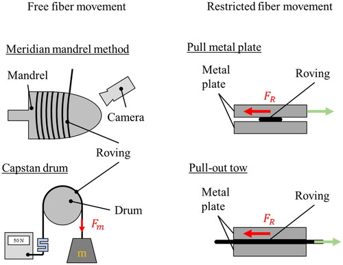
Various methods for measuring the sCoF of carbon fiber rovings are available, including shear testing and friction testing. Friction tests include the capstan method for determining the sCoF. Experiments to measure the adhesion behavior of individual fibers by the capstan method have been performed by Roselman et al. among others (Cornelissen et al., Citation2013; Roselman & Tabor, Citation1977). In capstan measurements, a fiber bundle is positioned over a roller with a predetermined weight at one end of the bundle. The resulting force is measured on the other side of the bundle. The losses between the weight-induced force and the measured force are used to infer the frictional force with the aid of the capstan equation. Koussios and Bergsma have developed a specially shaped winding mandrel for optically determining the slip behavior of a roving (Koussios & Bergsma, Citation2006). The mandrel was provided with a convex meridian profile to achieve a constant angular change during feed. The test is recorded using a camera system and subsequently, the critical angle and thus the sCoF can be determined via the point of slippage onset. This test setup was also chosen by Wang et al. (Citation2011). In addition to the friction tests, the sCoF can also be determined using shear tests. Here, the roving to be tested is fixed on a metal plate and then weighted down with another metal plate with a defined weight. The metal plates then move relative to each other, the friction force can be measured and the sCoF calculated. This method was chosen by Mulvihill et al., Dackweiler and Smerdova, among others, in their experiments to determine the sCoF (Dackweiler et al., Citation2019; Mulvihill et al., Citation2017; Mulvihill & Sutcliffe, Citation2017; Smerdova et al., Citation2021). schematically shows the mentioned methods for friction coefficient determination on fibers.
Figure 1. Schematic view on methods for friction coefficient determination.
The primary aim of the investigations in the present paper is to design and conduct an experiment, that can help to clarify the frictional behavior of towpregs (carbon fibers impregnated with high-viscosity resin) perpendicular to the longitudinal axis. Secondly, the influence of aging on the sCoF of towpregs is examined in this context.
2. Methodology and materials
To determine the sCoF µ, the frictional force is measured in the first step by using a special test setup and then calculated by applying the formula for determining the frictional force, considering the normal Force
according to Amonton:
The Amonton formula is employed, because it is not yet clear at this stage, whether Howell’s approach also applies to fiber materials impregnated with high-viscosity resin. With the Amonton formula, an easy comparison can nevertheless be made between the applied materials. The limitations in transferring the results to other measurement methods are known.
2.1 Test setup
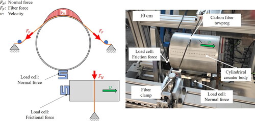
The test setup consists of a cylindrical surface that serves as a counterpart for the roving. The cylinder is made of an aluminum alloy (AlMgSi 0.5) and has a diameter of approx. 151 mm. The counterpart is pulled out under the roving during the test and the required force is recorded. The measuring principle enables a relative movement of the cylindrical body to a roving firmly clamped on both sides, transverse to the fiber orientation. Before starting the measurement, a 500 mm long roving is clamped at a wrapping angle of 11.4° onto the body with an adjustable contact force. The contact zone of the surface and the roving is located around the middle of the roving. Two mechanically decoupled load cells record both normal and frictional forces during the test procedure to determine the sCoF of the friction pairing. Due to the modular design of the tribometer, various measurement configurations can be realized by combining process and material parameters. This allows specific parameter settings to be made to obtain results for certain hypotheses. The forces to be measured result from the cylindrical body velocity and the fiber forces
. The testing rig is operated via a created graphical user interface (GUI) that uses a Raspberry Pi microcontroller. The GUI is in serial contact with an Arduino Uno, which takes control over a central of the actuators. The load cells, the electric motor, and the limit switches are connected to the Arduino Uno. A schematic of the forces acting and how the tribological device is set up appears in .
Figure 2. Schematic view of the forces (left) and the actual measuring device (right).
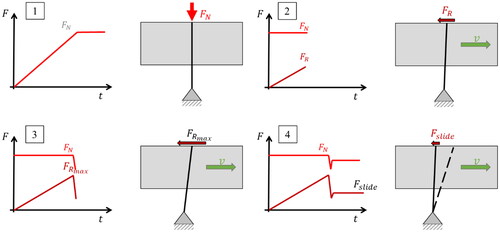
schematically shows the course of an ideal measurement. First, the normal force is increased until the defined level is reached. After a short phase, in which the forces stabilize, the test begins with the movement of the cylindrical counter body. The roving is deflected and the frictional force as well as the normal force are measured at the sensors. The build-up of the frictional force is linear. Once the maximum frictional force is reached, there is an abrupt drop in the frictional and normal force. The drop is followed by a transition to sliding friction. The coefficient of friction can then be calculated by using the measured normal force at the point, where the friction force drops abruptly.
Figure 3. Schematic view of the friction force measurement procedure.
2.2 Test procedure
As recommended in the data sheet, the tested towpreg was stored at approx. -18 °C in the airtight packaging applied by the manufacturer and removed from the cold store 24 h before the first tests. The towpreg was able to acclimatize at room temperature (21 °C) until the start of the test series the next day. The protective film was removed after acclimatization and the towpreg was exposed to ambient air. After opening, a defined length of towpreg was cut off and weighed to determine the fiber weight content. The surface of the test setup was brought to a defined roughness in the contact area by sandpaper (grit 240). Before each trial, the surface was cleaned with acetone to remove any resin remains or contamination, and a defined length of towpreg was cut for the first series of tests. To subtract the frictional effects of the movement associated with the test structure from the measured test data, a reference run without towpreg, and therefore without load, was carried out before each series of tests. Subsequently, the towpreg to be measured is fixed in the test setup and pretensioned to the previously defined fiber tension force by the clamping device. The fiber tension force increases by turning the two tensioning screws on the tensioning device slowly, piece by piece, and simultaneously in a clockwise direction. As soon as a difference of ±0.05 N to the intended fiber tension force is achieved, the adjustment process can be terminated. After the towpreg has been clamped, the test starts and the counterpart is pulled out from underneath the towpreg. The required tensile force, as well as the resulting normal force, is recorded during the entire experiment. For statistical validation, the tests are performed four times per parameter set, each time with a new section of towpreg. Relative to the old position, the fiber bundle is moved along the roving axis by at least 5 cm, but not more than 7 cm, and fixed again to ensure that the frictional effects of the previous measurement along the fibers do not affect subsequent measurements.
2.3 Design of experiments
For the trials, the following factors were investigated: the fiber force applied to the towpreg, the pull-off speed at which the counterpart is pulled under the towpreg, the aging of the towpregs, and the possible interactions of the individual points with each other.
The investigation aimed at obtaining a better understanding of the test procedure and the results of the test rig. shows the experimental design for the tests. Furthermore, the influence of the towpreg matrix aging on the sCoF was also intended to be studied by the tests. For inspecting the aging effects, the towpreg was taken out of storage for 43 days and then tested.
Table 2. Experimental design of pull-off speed and fiber force variations.
2.4 Material
In the following study, two pre-impregnated carbon fibers from different manufacturers and a non-impregnated dry carbon fiber were examined. The pre-impregnated fibers are commercially available towpregs, both of which have been specially developed for processing in filament winding technology and recommended for application in manufacturing pressure vessels. Both employ a high resin viscosity with a defined and consistent fiber volume content as well as a moderate tack to make processing possible.
Towpreg A is a system based on an epoxy resin from Westlake with a Formosa TC780 reinforcing carbon fiber. The fiber is a polyacrylonitrile-based carbon fiber with high strength and standard modulus, which is never twisted. The filament count of the towpreg is 24,000 with a specified fiber weight content as of 70% ± 1%. The relevant properties of the fiber are listed in .
Table 3. Fiber properties of Towpreg A, Towpreg B, and the dry fiber (Formosa Plastics Corporation, Citation2021; Mitsubishi, Citation2010; Toray Industries, Inc.).
The resin system for Towpreg A is a commercially available solvent-free, hot melt epoxy system with a high glass transition temperature (-DMA) of 130 °C that is specifically recommended for applications in manufacturing pressure tanks. The shelf life at different temperatures is of particular interest for the planned experiments. The properties of the resin system are shown in .
Table 4. Epoxy resin systems of Towpreg A and Towpreg B.
Towpreg B is also a system based on an epoxy resin from the towpreg manufacturer and a Mitsubishi Pyrofil TRH50 18K carbon fiber. The fiber is a polyacrylonitrile-based carbon fiber with high strength and standard modulus. The filament count of the towpreg is 18,000 with a specified fiber weight content of 70% ± 2%. The relevant properties of the fiber are listed in .
The resin system for Towpreg B is a development of the towpreg manufacturer. It is a solvent-free, epoxy system with a glass transition temperature (-DMA) of 102 °C. Here, the shelf life at different temperatures is of particular interest for the planned experiments, too. The properties of the resin system are shown in .
The dry fiber in the following investigations is a polyacrylonitrile-based Toray T700SC carbon fiber with high strength and standard modulus. The filament count of the fiber is 24,000 with an epoxy sizing. Details of the fiber properties are listed in .
3. Results
3.1 Preprocessing
shows an optimal shape of a measurement curve that can be applied for later evaluation. The overshooting of the measurement at the beginning of the curve due to the mass inertia of the test rig can be seen as well as the linear increase of the friction force afterward. After reaching the maximum frictional force, there is a sudden drop and subsequent transition to sliding friction.
Figure 4. Different types of measurement curves (A: Ideal, B: Sliding, C: Mix).
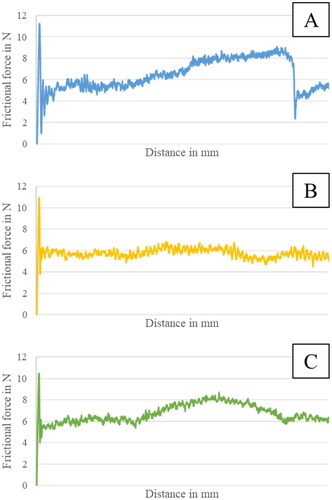
Different types of measurement curves were formed during the tests, which indicate differences in the friction behavior of the individual evaluations. shows several measured curves, that were recorded with the test rig. presents the ideal measurement curve from above, allowing the evaluation of the measurements. Graph B shows a pure sliding friction curve without an identifiable increase or drop in static friction. Although a linear increase in static friction force can be seen in measurement curve C, the instantaneous drop is missing.
For further investigations, those measurement curves, which showed clear and thus automatically evaluable curves (Type A), were filtered. All curves, for which there was no detectable increase (Type B) or clear drop (Type C) in friction force, were not considered for further analysis.
3.2 Findings
The findings from the performed tests are presented below. First, the influence of pull-off speed and the fiber force were investigated. These results were all generated with Towpreg A. Afterwards, the behavior of different materials (Towpreg A, Towpreg B, and dry fibers) is considered as well as finally the influence of the towpreg aging at room temperature on the coefficient of friction.
3.2.1 Process parameters
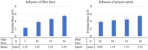
As can be seen from the results of the friction force investigation (), the friction force is dependent on both the fiber force set and the process speed. This leads to the conclusion, that with increasing fiber force and with increasing process speed, the measured frictional force also increases. The friction force increases nearly by a factor of 2.5 from 2.22 N to 5.44 N. The results for the increased fiber force are in line with the expected values. Since the normal force is directly dependent on the fiber force, the friction force increases due to the increase in normal force. The increase in frictional force when the processing speed is increased could be explained by the improvement of the resin strain rate as described by Kang et al. (Citation2018), but this is still being investigated further.
Figure 5. Influence of fiber force and process speed on friction force.
3.2.2 Material
Next, another commercially available towpreg and a dry carbon fiber roving were compared to the Towpreg A with the same set of parameters. As expected, the applied friction force of the dry fibers is significantly below the towpregs. In addition, it can be seen that the friction force that can be applied with Towpreg B is nearly nine times higher than the dry fiber and three times higher than Towpreg A ( and ).
Figure 6. Comparison of the towpreg and dry fiber fiction force (Ff) (3.8 N normal force, 2.51 mm/s process speed).
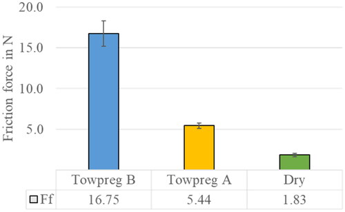
Figure 7. sCoF for Towpreg A, Towpreg B, and dry fibers
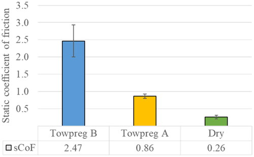
If the Coulomb friction values for the different materials are calculated from the measured friction and normal force, the following results are obtained:
The calculated sCoF values of 0.26 for the dry fibers are in agreement with those found in the literature (Li & Lin, Citation1987; Roselman & Tabor, Citation1977). Values for sCoF of 0.86 were calculated for Towpreg A. These are significantly higher than those obtained for the dry fiber and higher than those found in the literature for wet fibers impregnated with fresh resin. The sCoF for the Towpreg B is 2.47, which is significantly higher than 1, suggesting that additional effects are taking place to increase the frictional force. This behavior also occurs during the contact of rubber tires with other surfaces. Thus, coefficients of friction well above 1 can be achieved when rubber and glass are in contact (Tolpekina & Persson, Citation2019).
The work of Crossley, Budelmann, and others (Budelmann et al., Citation2019; Crossley et al., Citation2011; Kang et al., Citation2018) provides explanations for this behavior. They have shown, that the frictional behavior of higher viscosity materials is strongly dependent on their viscoelastic properties. The Dahlquist criterion is a widely accepted standard, based on the viscoelastic modulus to determine how well a material is in contact with a surface (Chang, Citation1991). With a higher modulus, the material is too stiff to deform. In this case, the material cannot adapt to the microscopic surface topography and the real contact area decreases. If the stiffness of the resin decreases, mainly due to higher temperatures, the resin can fit well to the surface, but failure occurs within the resin. This means, that the main reason for the different sCoF from the tests is probably the different viscoelastic behavior of the resin systems of the two towpregs. These observed effects must therefore be further investigated and analyzed.
3.2.3 Aging
In the next step of the analysis, we look for the effect of aging on adhesion over a period of 43 days. As can be seen in , there is an increase in the frictional force after the towpregs have been removed from storage within the first 43 days. The behavior of the increasing friction force can be observed across all parameter sets that were investigated.
Figure 8. Friction force over an aging period.
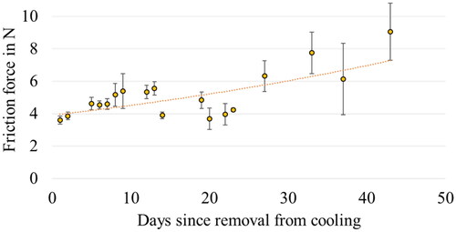
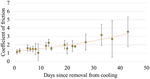
The calculation of the sCoF also shows an increase with increasing age of the towpregs (). Also clearly visible is the exceeding of the sCoF to values clearly above three. It can therefore be assumed, that the effects which increase the sCoF above 1 occur more strongly with aged towpregs. As with the different towpreg materials, the reason for the change in sCoF over the aging period can probably be found in a change in the viscoelastic behavior of the resin system. The chemical cross-linking of the resin system is accelerated after removing the towpreg from storage in the freezer and leads to an increase in resin stiffness and thus to a better transfer of shear forces within itself. Since we are only dealing with a marginal increase in stiffness at the beginning of curing, the adaptation to the surface still works well.
Figure 9. sCoF over an aging period.
4. Conclusions
The study investigated the frictional behavior of carbon fiber-reinforced plastic towpregs in the context of filament winding processes. The sCoF between towpregs and the winding surface is a critical parameter that directly influences the quality of wound components. The research findings presented herein shed light on different factors that affect frictional behavior and contribute to a deeper understanding of the filament winding process involving CFRP towpregs.
The experimental investigation encompassed a comprehensive analysis of the sCoF through various trials and measurements. The following can be summarized from the findings and the resulting questions for further investigation:
4.1 Influence of process parameters
The investigation revealed a clear dependence of the measured frictional force on both the fiber force applied to the towpreg and the pull-off speed of the winding process. Increasing fiber force and process speed resulted in higher measured frictional forces. This observation aligns with the expectation that greater forces and speeds contribute to higher friction due to increased contact interactions.
4.2 Comparison of materials
Comparative analysis of different towpregs and dry fibers highlighted substantial differences in friction forces, reinforcing the importance of material selection in filament winding processes. Towpreg B exhibited a notably higher friction force, emphasizing the impact of resin system characteristics on frictional behavior. The observed phenomena, exceeding a sCoF of 1, were attributed to the viscoelastic properties of the resin systems and require further investigation. The observed differences in frictional properties among different towpregs suggest a significant influence on the viscoelastic properties of the resin systems. A more detailed analysis of these properties could provide insights into how viscoelasticity affects friction and how it interacts with other process parameters.
4.3 Calculation of sCoF
Calculated sCoF values for the materials provided further insights. The sCoF for dry fibers aligned well with values reported in the literature. The sCoF for Towpreg A was notably higher, indicating a strong frictional interaction. The sCoF for Towpreg B was surprisingly much higher than for Towpreg A, implying additional complex effects in the interaction between the towpreg and the surface.
4.4 Aging effects
The study investigated the effect of aging on towpregs over 43 days. Results indicated an increase in frictional force and sCoF with aging, possibly linked to accelerated chemical cross-linking of the resin system and the associated change in viscoelastic behavior. This finding underscores the importance of considering the age of towpregs in filament winding applications, as aging appears to influence the frictional properties of the material. A more extended investigation into the long-term aging effects on towpregs could provide valuable information. Understanding, how the frictional properties evolve over extended storage durations and under varying environmental conditions, is crucial for practical applications and will be carried out shortly.
4.5 Additional planned research work
In the current study, only the contact between the fiber and the metallic surface was investigated. However, since this is only the so-called first layer problem, and after the first layer is deposited on a fiber surface, the direct fiber-fiber contact will need to be investigated in the next studies. In addition, the effect of temperature on the frictional behavior of towpregs will be systematically investigated.
The findings of this study underscore the significance of selecting appropriate materials and understanding their frictional interactions for use in filament winding. Moreover, the temporal aspects of material behavior, as exemplified by aging effects, demonstrate the demand for comprehensive consideration in manufacturing processes.
Acknowledgment
The studies were carried out as part of the publicly funded project “MaTaInH2”. The project “MaTaInH2—Material efficient and cycle time optimized industrialization of H-pressure tanks” is funded by the German Federal Ministry of Transport and Digital Infrastructure (BMVI) based on a resolution of the German Bundestag within the program “National Innovation Program Hydrogen and Fuel Cell Technology Phase (NIP II)” (funding code 03B10111C).
References
- Abdalla, F. H., Mutasher, S. A., Khalid, Y. A., Sapuan, S. M., Hamouda, A. M. S., Sahari, B. B., & Hamdan, M. M. (2007). Design and fabrication of low-cost filament winding machine. Materials & Design, 28(1), 234–239. https://doi.org/10.1016/j.matdes.2005.06.015
- Azeem, M., Ya, H. H., Alam, M. A., Kumar, M., Stabla, P., Smolnicki, M., … Mustapha, M. (2022). Application of filament winding technology in composite pressure vessels and challenges: a review. Journal of Energy Storage, 49, 103468. https://doi.org/10.1016/j.est.2021.103468
- Budelmann, D., Detampel, H., Schmidt, C., & Meiners, D. (2019). Interaction of process parameters and material properties with regard to prepreg tack in automated lay-up and draping processes. Composites Part A: Applied Science and Manufacturing, 117, 308–316. https://doi.org/10.1016/j.compositesa.2018.12.001
- Chang, E. P. (1991). Viscoelastic windows of pressure-sensitive adhesives. The Journal of Adhesion, 34(1-4), 189–200. https://doi.org/10.1080/00218469108026513
- Cohen, D. (1997). Influence of filament winding parameters on composite vessel quality and strength. Composites Part A: Applied Science and Manufacturing, 28(12), 1035–1047. https://doi.org/10.1016/S1359-835X(97)00073-0
- Cornelissen, B., de Rooij, M. B., Rietman, B., & Akkerman, R. (2013). Frictional behaviour of high performance fibrous tows: A contact mechanics model of tow–metal friction. Wear, 305(1-2), 78–88. https://doi.org/10.1016/j.wear.2013.05.014
- Crossley, R. J., Schubel, P. J., & Warrior, N. A. (2011). Experimental determination and control of prepreg tack for automated manufacture. Plastics, Rubber and Composites, 40(6-7), 363–368. https://doi.org/10.1179/174328910X12777566997810
- Dackweiler, M., Hagemann, L., Coutandin, S., & Fleischer, J. (2019). Experimental investigation of frictional behavior in a filament winding process for joining fiber-reinforced profiles. Composite Structures, 229, 111436. https://doi.org/10.1016/j.compstruct.2019.111436
- Formosa Plastics Corporation (2021). Formosa TC780-Technical data sheet.
- Howell, H. G., & Mazur, J. (1953). Amontons’ law and fibre friction. Journal of the Textile Institute Transactions, 44(2), T59–T69. https://doi.org/10.1080/19447025308659728
- Kang, C., Shi, Y., Yu, T., Zhao, P., Deng, B., Chen, Z., & Zhang, H. (2018). Experimental investigation of friction between prepreg tape and compaction roller for prepreg tape hoop winding. Journal of Reinforced Plastics and Composites, 37(12), 853–862. https://doi.org/10.1177/0731684418764018
- Koussios, S. (2004) Filament winding: a unified approach [Dissertation]. TU Delft.
- Koussios, S., & Bergsma, O. K. (2006). Friction experiments for filament winding applications. Journal of Thermoplastic Composite Materials, 19(1), 5–34. https://doi.org/10.1177/0892705706049561
- Lengsfeld, H., Wolff-Fabris, F., Krämer, J., et al. (2015). Faserverbundwerkstoffe: Prepregs und ihre Verarbeitung. München: Hanser.
- Li, X., Lin, D. (1987). Non-geodesic winding equations on a general surface of revolution. Proceedings for the 6th International Conference on Composite Material.
- Mitsubishi (2010). Grafil Pyrofil TRH 50 18K-Technical information.
- Mulvihill, D. M., & Sutcliffe, M. P. F. (2017). Effect of tool surface topography on friction with carbon fibre tows for composite fabric forming. Composites Part A: Applied Science and Manufacturing, 93, 199–206. https://doi.org/10.1016/j.compositesa.2016.10.017
- Mulvihill, D. M., Smerdova, O., & Sutcliffe, M. P. F. (2017). Friction of carbon fibre tows. Composites Part A: Applied Science and Manufacturing, 93, 185–198. https://doi.org/10.1016/j.compositesa.2016.08.034
- Peters, S. T. (2011). Composite filament winding. Materials Park ASM International.
- Roselman, I. C., & Tabor, D. (1977). The friction and wear of individual carbon fibres.
- Rubenstein, C. (1959). Review on the factors influencing the friction of fibres, yarns and fabrics. Wear, 2(4), 296–310. https://doi.org/10.1016/0043-1648(59)90267-4
- Smerdova, O., Benchekroun, O., & Brunetiere, N. (2021). Transversal friction of epoxy-lubricated and dry carbon tows: From initial stages to stabilised state. Composites Part A: Applied Science and Manufacturing, 143, 106263. https://doi.org/10.1016/j.compositesa.2020.106263
- Tolpekina, T. V., & Persson, B. N. J. (2019). Adhesion and Friction for Three Tire Tread Compounds. Lubricants, 7(3), 20. https://doi.org/10.3390/lubricants7030020
- Toray Industries, Inc. (2020). Toray Torayca Yarn—Product specification.
- Wang, R., Jiao, W., Liu, W., Yang, F., & He, X. (2011). Slippage coefficient measurement for non-geodesic filament-winding process. Composites Part A: Applied Science and Manufacturing, 42(3), 303–309. https://doi.org/10.1016/j.compositesa.2010.12.002
- Yuksekkay, M. E. (2009). More about fibre friction and its measurements. Textile Progress, 41(3), 141–193. https://doi.org/10.1080/00405160903178591
- Zu, L., Zhu, W., Dong, H., & Ke, Y. (2017). Application of variable slippage coefficients to the design of filament wound toroidal pressure vessels. Composite Structures, 172, 339–344. https://doi.org/10.1016/j.compstruct.2017.03.094